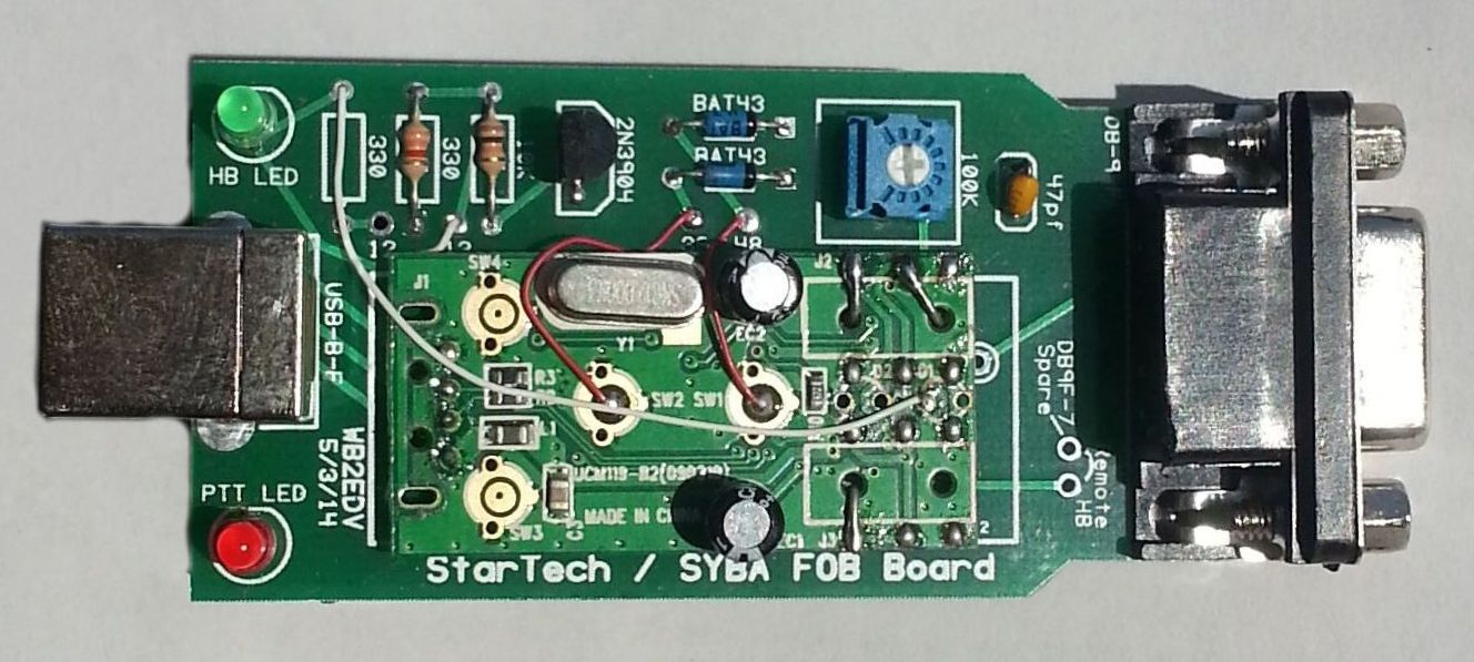
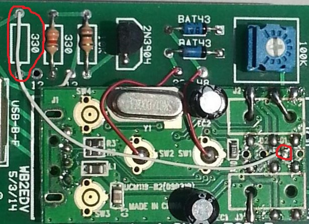
Below - Photo 1 - SYBA UAUD71 sound adapter mounted to the WB2EDV circuit board.
SYBA UAUD71 USB sound adapter modification
to CM119 based radio interface
For AllStar - Asterisk - app_rpt
By Kevin Custer - W3KKC
|
The device is mostly surface mount, but, depending on your skill level can be modified into an inexpensive USB radio adapter/interface. The instructions provided here will help with the modification of this device to bring out all of the inputs and outputs. The construction practice I chose uses WB2EDV's printed circuit board. Please read the entire article before starting this conversion - as it's fairly involved! |
Below - Photo 1 - SYBA UAUD71 sound adapter mounted to the WB2EDV circuit board.
Concept:
The article presented here was the result of modifying a SYBA UAUD71 USB
sound FOB for use with Chuck Kelsey's printed circuit board. This concept makes
use of a $10 USB FOB, some fairly common components, and a small custom circuit board to
build an inexpensive, but professional looking and working USB radio adapter/interface for AllStar.
Conversion:
Start the conversion by carefully opening the device. Be careful that you don't cut
yourself or run a jeweler's screwdriver through your hand. This process is much like opening
a clam shell - using a pocket knife or small screwdriver with caution. It might be helpful
to grasp one half of the case in a small vice. Also, be careful not to ram the knife or
whatever into the interior of the unit, otherwise damage to the PC board or components can result.
Remove the USB connector from the FOB. It will be replaced later with resistor clippings or small diameter solid hook-up wire about 1/2" long in each of the 4 holes.
Remove the audio jacks by cutting the straps on each side of the jack and desoldering the ends which remain. You have to be careful as the board is fragile and the circuit traces can lift. See the photo below for a detail of the removed audio jacks.
Carefully remove the two LEDs and save them. They can be reused if you aren't going to be installing the optional plastic cover.
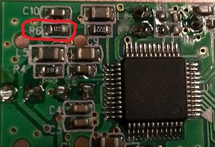
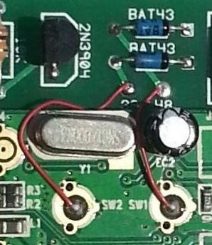
Remove the bias resistor R6 on the CM119 side of the board. This chip resistor (R6 - 1.2k ohm) normally supplies voltage to the electret condenser microphone. These microphones have an internal audio amplifier which requires voltage to operate. The removal of this resistor does two things: First, it removes the voltage on this lead eliminating the need for another coupling capacitor. Secondly, it raises the input impedance from 1.2k to the value of the input control potentiometer - 100k ohms. See the photo below for a detail of the location of this resistor.
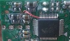
The next step makes a connection to pin 13 on the CM119. This pin produces the Push To Talk (PTT) signal, but it needs to be buffered with a transistor so it can sink enough current to be compatible with most transmitters. This step is one of the most difficult, as soldering to one of the 48 pins of the chip, without shorting something out, can prove to be difficult. To make this connection, I use "Kynar" wire. This is 30 gauge 'wire wrap' wire. Since the connection is on an end (corner) conductor, and because there is enough space to slide the insulated wire underneath the complete row of 12 pins, this process makes an easier time of it. Sliding the wire under the pins holds it in place while soldering. I begin by stripping about 1/16" of insulation from a 2" piece of wire and sliding it in from the opposite end. Then, with the end of the insulation lined up with the very end of the pin, bend the wire conductor over so it lays beside the pin and carefully solder. See the photo below for a detail of the location of the wire. (Note that R6 has been removed.)
Solder wires into the four holes vacated by the removal of the USB connector. These wires will line up with the four holes in the WB2EDV board. Solder resistor clippings or small diameter solid hook-up wire about 1/2" long in each of the 4 holes Then install the FOB board onto the circuit board making the two boards as close as possible. There are two integrated circuit packages on one side of the board (the side that mates with Chuck's board). These serve as spacers keeping the two boards separated, insuring that nothing gets shorted out.
Solder the opposite end of the wire that was connected to the CM119 pin 13 (PTT) to the hole on the circuit board marked "13" between the 10k and 330 ohm resistors.
Wire up the 'hardware' COS and CTCSS (PL) inputs by soldering wires to pads that were originally designed as push-button switches SW1 and SW2. There is a membrane holding the convex switch disc pads in place. Use a knife or jeweler's screwdriver to pry this membrane and metallic switch discs from the board, revealing the circuit traces under them. The outer ring is ground, the inner circle is the pad you want to make connection to. See the photo below for a detail of the location of the wires.
Solder wires to connect the left and right audio output pads, and MIC input pad to the circuit board. These are connected to holes left by removing the two audio jacks and run to corresponding holes in the larger circuit board. See the photo below for a detail of the location of the wires.
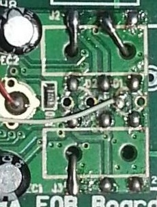
Solder a wire jumper from the vacated "D1" LED hole (second hole in from the edge of the board) to the pad shown in the photo below. The HeartBeat (HB) LED current limiting resistor (330 ohm) is not installed because one already exists on the SYBA UAUD71 circuit board. Remember, Chuck's board will work with 3 different FOBs, so construction will differ between the three.
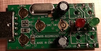
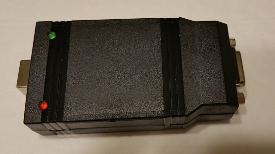
Refer to the parts list and install the remaining components onto the circuit board. The completed interface can be mounted on a blank PCI slot cover or one machined to have a DE-9 hole. The PTT and HB LEDs can be remotely mounted on the slot cover. The completed board can be installed into an optional plastic case. If the plastic case is used, the LED's leads should be left long. The case can be drilled to allow the LEDs to stick through the upper case half for visibility. If the plastic case isn't used, the LEDs removed from the SYBA board can be re-mounted onto the WB2EDV board. Of course, you can be resourceful and lengthen the original LED leads so they extend through the case. The LEDs have a flat side and the board has a silkscreen outline which includes a flat side. Insure you orient the polarity of the LEDs correctly!
Completed board installed into optional plastic case. Holes were drilled to allow the LEDs to stick out for visibility.
Parts List:
1 - USB-B Jack Mouser 649-61729-1011BLF
1 - DE-9 Female Mouser 152-3409
1 - 100k Trimmer Mouser 652-3362P-1-104LF
1 - 2N3904 Transistor Mouser 2N3904TFR
2 - BAT43 Diode Mouser 511-BAT43
1 - 47pF Capacitor Mouser 140-100N5-470J-RC
1 - 330 ohm Resistor Mouser 660-CF1/4C331J
1 - 10k Resistor Mouser 291-10K-RC
1 - LED Red Mouser 696-SSL-LX5093ID125
1 - LED Green Mouser 696-SSL-LX5093PGD
1 - Sound FOB SYBA UAUD71
1 - WB2EDV circuit board.
1 - Cover PC Slot Expansion cover w/DE-9 cutout (optional)
1 - Plastic Case Mouser 616-73094-510-000 (optional)
DE-9 Pinout:
1 - Encode sub-audible tone to TX (See Note A)
2 - Audio to TX
3 - COS logic from RX (See Note B)
4 - CTCSS logic from decoder (See Note B)
5 - PTT to TX
6 - Discriminator audio from RX
7 - Spare (could use to remote HeartBeat (HB) LED
8 - Ground
9 - Ground
Notes:
A - Not used if transmitter encoder is utilized.
B - Not used when utilizing DSP.
Option - LEDs can be mounted on PC slot cover.
HB LED (green) blinks when the device is recognized by PC.
PTT LED (red) is on when the transmitter is keyed.
I hope you have enjoyed this article.
73,
Kevin Custer - W3KKC
Email Kevin Custer - W3KKC for email support of this modification.
Email Chuck Kelsey - WB2EDV to inquire about FOB circuit boards.
Article by Kevin Custer - W3KKC, all rights reserved.
Circuit board courtesy of Chuck Kelsey - WB2EDV
Specifications may change without notice.
Copyright 2014, Kevin Custer - W3KKC.
Photos property of Kevin Custer - W3KKC.
HTML November 1, 2014, W3KKC - All Rights Reserved!
This web page, this web site, the information presented in and on its pages and in these modifications and conversions is © Copyrighted 1995 and (date of last update) by Kevin Custer W3KKC. All Rights Reserved, including that of paper and web publication elsewhere.