
An Audio-Noise-Based Voting Circuit
By Mark
Kolber WB2WHC
134 Merry Dell Drive
Churchville PA 18966
This article originally appeared in October 1992 issue of QST magazine.
This article has been reproduced here in html with permission from QST / ARRL
The following article is about a 2 channel signal-to-noise voter.
Not a politician, this candidate delivers what it promises --- the best signal available!
As hand-held transceivers (H-Ts) become smaller, and low power, battery conserving operation becomes more popular, the disparity between the transmitting range of a typical 100 watt repeater compared to the repeater accessing range of a typical 1 watt or less H-T becomes more and more apparent. How often have you found it difficult (or impossible) to access a repeater with a low power H-T even though you can hear the repeater at full quieting? This can happen even if the repeater is equipped with a high sensitivity, state-of-the-art receiver. Here's where diversity reception and voting circuits can play an important and helpful part. Diversity reception improves a repeater's receiving capability by making use of a second receiver tuned to the repeater's input frequency. This receiver is sometimes located at the main repeater site and connected to a separate antenna. More often, however, the second receiver is at another site in an area not well covered by the main site receiver. So positioned, this second receiver is sometimes called a satellite receiver. The signal received by the satellite receiver is relayed to the main repeater site via a radio (or wire) link. In either case, the satellite receiver provides enhanced receiving capability for the repeater. At the main repeater site, a voting circuit selects the better of the two received signals and sends the chosen signal to the repeater's transmitter. If only one of the two receivers is able to hear the signal, the job of selecting the better signal is easy! Often, however, both receivers can hear the signal. Then, only the receiver with the better signal must be selected. Why? Because simply adding the two audio signals from both receivers results in a signal that is nearly as noisy as the noisier of the two signals. We want only the quieter signal. That's the function of a voting circuit: It votes for the receiver with the better signal. Some voting circuits work by comparing the S-meter or AGC voltage level of the two receivers and selecting the audio from the receiver with the greater amplitude. Although this method can work well, it has two problems. Because the satellite receiver often is remotely located, a telemetry system is required to relay the satellite receiver's S-meter reading (as well as its audio output) to the main site so that the satellite and main receiver S-meter readings can be compared. Also, selecting the receiver with the higher S-meter reading doesn't always yield the quieter audio. For example, a receiver that's in a high noise area, or is affected by desense, may have a higher S-meter reading, yet it delivers noisier audio than the other receiver, which may be in a quiet area. The voting circuit described here compares the noise levels within the two audio signals and selects the signal with the lower audio noise level and better quieting. Because this method uses only the audio signals, no telemetry information from the satellite, or local receiver, is needed. Only the carrier operated relay (COR) and audio signals from the two receivers are used.
Theory of Operation:
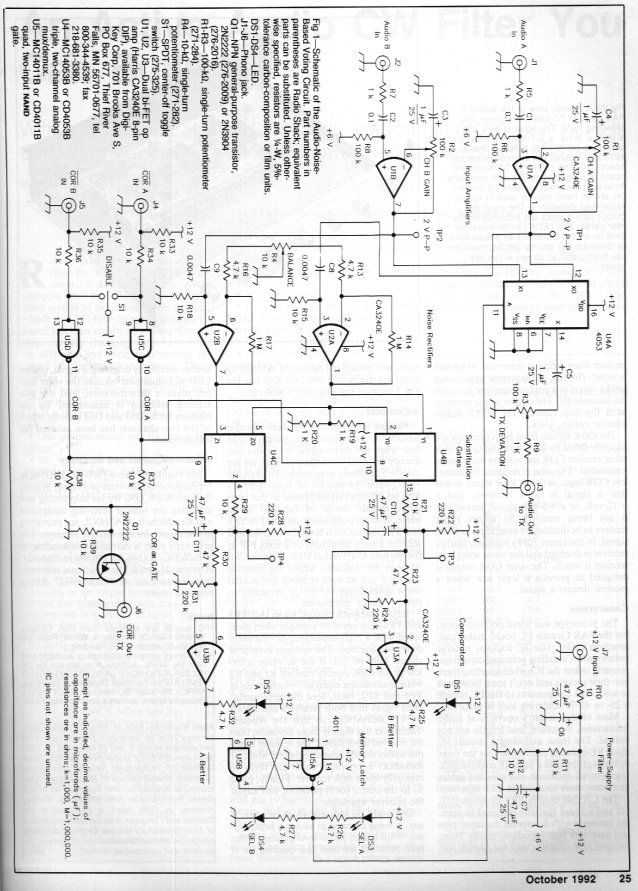
Refer to Fig 1. The incoming audio signals from the two receivers are
amplified by U1A and U1B and adjusted to equal output levels by GAIN
potentiometers R1 and R2. It's important that the two output levels
be matched so that the voter can make a fair comparison. The audio signals
are fed to U4A, which acts as an SPDT switch and selects one signal to
be fed to the repeater transmitter via level setting control R3, TX
DEVIATION. The audio signals are also fed through high pass
filters consisting of R15, R18, C8 and C9, which attenuate the lower frequency
audio components. The higher frequency components are fed to the half wave
noise rectifiers U2A and U2B. At U2A and U2B, the audio signals are
half wave rectified by the zero biased op-amp noise rectifiers. These op-amps
rectify by amplifying only the positive going portion of the audio. The
rectified outputs pass through U4B and U4C acting as SPDT switches. These
switches substitute a fixed 6-V dc level for the noise rectifier output
when the associated receiver COR is closed. This causes the voter
to consider a receiver that is not receiving a signal (and has a closed
squelch) as having a very noisy audio output, rather than no audio output.
This is done so that if one receiver has a closed squelch with no audio
output, and the other receiver has an open squelch, the voter will select
the receiver with the opened squelch regardless of how noisy that signal
may be. Dc voltages output from the noise substitution gates and
noise rectifiers are filtered by RC circuits R21/C10 and R29/C11, which
average the dc voltage before comparison. Such averaging causes the
voter to ignore short transient effects when comparing receiver signals.
At these RC circuits, and TP3 and TP4, the filtered dc voltages represent
the average quieting level of the two receiver signals. A lower voltage
represents more quieting. After being reduced by about 20%, each
of these two voltages are compared to the voltage from the other channel.
The channel with a voltage 20% or more lower than the opposite channel
is selected as the better channel. Resistive dividers, R23/R24 and
R30/R31 perform the necessary 20% quieting voltage reduction for the comparison.
When both receivers are fully quieted, both channels have nearly the same
detected voltage because they have the same audio, and neither channel
is chosen as being better. The set/reset memory latch flip-flop (U5A and
U5B) remembers which channel was the last one selected as the better one
and maintains that selection. This causes the voter to stay with the currently
selected receiver when it cannot determine which one is better. (In this,
the electronic voter is not unlike voters in a political election: It favors
the incumbent!) The output of the memory latch flipflop controls the SPDT
audio selector switch, U4A. The COR signals from both receivers are
logically ORed by R37, R38 and Q1 so that either receiver COR can activate
the repeater transmitter. The voter is designed for active low COR logic.
A 0 volt logic signal means that a signal is being received, and a +12-volt,
or a + 5 volt signal, means one is not being received. S1 allows either
receiver to be disabled by overriding its COR signal. In the center (OFF)
position, neither receiver is disabled and the voter selects the receiver
it wants. The voter COR output is designed to provide a logic low when
a receiver detects a signal.
Construction:
Click Here to view the schematic.
Click Here to view one horizontally-oriented.
The prototype was wired point-to-point, but the FAR Circuits PC board
makes construction easier. Use IC sockets, observe polarity when installing
polarized capacitors, properly orient the ICs when inserting them into
their sockets and don't use a blowtorch to solder the components to the
PC board: a 25- to 40-W soldering iron is sufficient. Most of the
circuitry operates at audio frequencies, therefore, lead lengths are not
critical. The input and output circuits include RF isolation resistors
so that the voter operates properly in a high RF environment. Use
a metal enclosure and shielded cables and connectors to assist in RF rejection.
The CA3240 dual bi-FET op amps (U1, U2 and U3) are specially designed to
operate correctly with 0 volts on the input pins and have very high impedance
inputs. Note: 741 and 1458 op amps will not operate correctly and should
not be used! CA3240E op-amps are available from sources on the Next Page.
Adjustment:
Because the voter uses the receiver audio signals for comparison, the
system works best when the audio signal levels and frequency response from
the two receivers are matched as closely as possible. To align the voter,
open the squelch of both receivers with no RF input signal present so that
both audio signals consist of full level audio noise. With an oscilloscope
attached to TP1 and TP2, adjust each GAIN control,
R1 and R2, for a noise amplitude of 2 volts P-P at the outputs of U1A and
U1B. If an oscilloscope is not available, adjust the controls for a 0.5-volt
ac level at those test points; use a series connected 0.l uF capacitor
to remove the dc component. Adjust BALANCE
control R4 so that TP3 and TP4 have equal dc voltages when measured with
a high impedance dc voltmeter or an oscilloscope. The voltages measured
should both be +3. If the dc value is too low or too high, equally
readjust R1 and R2 while maintaining equal ac voltage levels at TP1 and
TP2. Next, feed the same modulated signal into both receivers and adjust
R3 TX DEVIATION so that the repeater transmitter
has slightly more deviation than the received input signal. The repeater
transmit audio should sound the same when S1 DISABLE
is operated back and forth to manually select each receiver. Finally, place
S1 in the center OFF position, and adjust the
receiver squelches. DS1 and DS2 indicate which receiver, if any,
is being detected as having a better signal. With a high audio level present,
when both receivers are near full quieting, or if neither receiver
is detecting a signal, neither LED will illuminate because the voter cannot
make a determination, and the pre-existing selection is maintained by the
memory latch. DS3 and DS4 indicate which of the two channels has been selected
for transmission.
Acknowledgments and Summary:
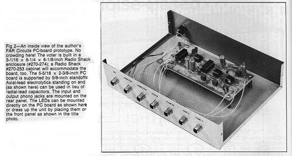
Click Here for an inside view of
the voter.
My thanks to Steve DeWell, KB7NKB, for constructing the voter prototype,
Woody Boehm, WB9CQX, for his help testing and installing the remote receiving
equipment and Ken Nichols, WA7HXZ, for providing us with a site for the
satellite receiver. The prototype voter is currently in operation
on WB2WHC/R (146.36/146.96) in Phoenix, Arizona.
Notes:
PC boards are available from:
FAR Circuits
18N640 Field Court
Dundee. IL 60118.
(847) 836-9148 Voice/Fax
Look under the Repeater Controller and Accessories page link.
Price: $6, plus shipping and handling.
About the author:
Mark Kolber has been an Amateur Radio operator since
1966. He holds an Advanced class ticket and operates mostly 2- and 10-meter
FM. In 1973, Mark earned a BSEE degree from The New Jersey Institute of
Technology, Newark, New Jersey (Formerly Newark College of Engineering).
After moving to Arizona in 1984, he earned an MSEE degree from Arizona
State University, Tempe, Arizona, in 1989.
Mark is employed by Motorola,
in the DNS (Digital Network Systems) Division in Horsham, (PA) specifically
in the (CATV) Headend equipment design group.
Next Page, Notes about using positive logic COS with circuit diagrams, reducing the time constant for faster voting, and other thoughts.
This article is part of the information available
from "The Repeater Builder's Technical Information Page"
Original Copyright© October 1992 Mark Kolber WB2WHC, and QST, all rights
reserved.
html Copyright© January 2000 Kevin K. Custer,
all rights reserved.