Back to Home
Motorola R2001-series
Communications Systems Analyzers
By Steve Goggans K7LZJ and
Robert W. Meister WA1MIK

|
Back to Moto Test Equipment Back to Home |
Extenders for the Motorola R2001-series Communications Systems Analyzers By Steve Goggans K7LZJ and Robert W. Meister WA1MIK |
|
Background:
Alignment and repair of the R2001 series communications service monitors requires that some assemblies be extended out of the card cage. A few of the modules also require that RF signals be extended as well.
The Motorola R200X series extender kit, RPX4150A, contains 72- and 100-pin extender boards, 5- and 10-pin extension cables (for the A2 board cables), and three RF extender (coaxial) cables. Naturally this kit and its components are No Longer Available.
72- and 100-pin Extender Boards:
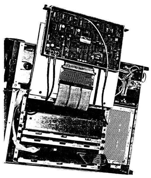
The original extender boards are flexible. They consist of card edge connectors joined by several flat cables about a foot long. This let you extend a board and place it flat on some insulated material (such as the service manual) on top of the card cage so you can work on the component or solder side of the board. The image below shows the A4 card extended, courtesy of the RPX4150A manual.
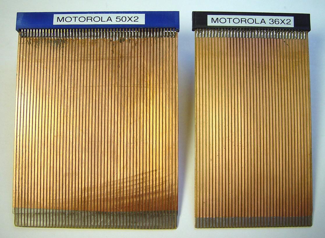
Vertical, non-flexible (rigid) extender boards can be purchased in kit form (you do the soldering) or fully assembled on a popular auction site. You may need to use some thin stiff material behind or in front of the extended assembly, especially the ones enclosed in a cast aluminum case such as A4 and A5, as they're heavy and will want to tilt in one direction or the other. You do NOT want to break one of the motherboard connectors! This may be one benefit of the flexible extenders sold by Motorola. The photo below shows one of each of these rigid extender boards.
5- and 10-pin Extension Cables:
These cables are used exclusively with the A2 (Scope Amplifier) card to extend the cables that go to the CRT socket and High Voltage Power Supply. You can make your own 5- and 10-pin extension cables with some hookup wire and the following Digikey parts for just a few dollars.
| Part Number | Description | Qty |
|---|---|---|
| WM2014-ND | CONN HOUSING, 5 POS, 0.100 W/RAMP | 1 |
| WM2019-ND | CONN HOUSING, 10 POS, 0.100 W/RAMP | 1 |
| WM1114-ND | CONN TERMINAL, FEMALE, 22-30AWG TIN | 15 |
| WM4203-ND | CONN HEADER, 5 POS, 0.100 VERT TIN | 1 |
| WM4208-ND | CONN HEADER, 10 POS, 0.100 VERT TIN | 1 |
| - - - - - - - - - - | 6-8 inch long pieces of multi-colored insulated #22 stranded wire | 15 |
| - - - - - - - - - - | 1/2 inch long pieces of 3/32 inch heat shrink tubing | 15 |
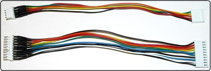
The wires get tack-soldered to the sides of the short pins on the (male) header, and pieces of heat shrink tubing are slipped over the wire and solder joint insulation. The female terminals at the other end are crimped and/or soldered before being inserted into the housing. Check the orientation of the A2 connectors so the wire colors agree with the pin numbers. Here's a photo of the completed A2 extension cables.
RF Extender Cables:
Proper RF extender cables are rarer than hen's teeth. Thanks to a "knowledgeable person" who actually has this kit, the RF connectors used on A4 and A5 were identified as "OMQ Rack and Panel connectors" made by Omni-Spectra around 1973 for National Radio Astronomy Observation. Various write-ups mention "Satisfactory for 1-2 GHz and show no evidence of not being applicable over the full rated range of DC to 4 GHz." The OMQ 3043-75 mounted tight to a card chassis (hard-line version). The OMQ 3033-75A had a spring washer so it would float a bit for alignment on the motherboard. A web search will turn up plenty of information on OMQ connectors except where to buy them. The BAD news is they haven't been available for dozens of years. The GOOD news is the centers are very close in dimension to SMA connectors. They have an outer assembly that guarantees a good ground connection without the retaining nut that's found on standard SMA connectors.
A point to ponder: when was SMA "invented"? Wikipedia states SMA was developed in the 1960s as a minimal connector for use from DC to 18 GHz.
Is SMA a Reverse-Polarity (RP) OMQ with a retaining nut and no outer shield? Is an RP-SMA the basis for the original OMQ center?
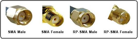
Just so we all know what's what, a standard SMA Male has an exposed male contact (pin) and a retaining nut, while a standard SMA Female has an enclosed female contact (receptacle) and no retaining nut. RP connectors reverse the inner contacts, so an RP-SMA Male has an enclosed female contact (receptacle) and a retaining nut, while an RP-SMA Female has an exposed male contact (pin) and no retaining nut. These differences are summarized in the table and photo below.
| SMA Male | SMA Female | RP-SMA Male | RP-SMA Female | |
|---|---|---|---|---|
| Contact Type | Male Pin | Female Socket | Female Socket | Male Pin |
| Center Contact | Exposed | Enclosed | Enclosed | Exposed |
| Retaining Nut | Yes | No | Yes | No |
The following montage shows the various connectors in the same order as above.
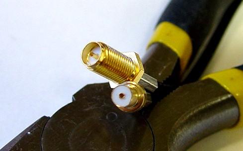
The module connectors have a female socket contact making it an RP-SMA Male, and the motherboard connectors have a male pin contact making it an RP-SMA Female. The extension cables need an RP-SMA Female to mate with the module connectors and an RP-SMA Male to mate with the motherboard connectors. The photo below shows the connectors on the A4 module (RP-SMA Male) and in the cavity beneath it (RP-SMA Female).

The extender cables can be fabricated using an RP-SMA Male with the retaining nut removed and an RP-SMA Female (chassis-mount preferred). The cable shield connection will not be as good or RF-tight as it was with the original OMQ connectors but for tune-up it's good enough!
Originally I thought the SMA and RP-SMA center pins were just swapped between the male and female connectors. The correct RP pins are different length than the regular pins when compared side by side. The exposed amount of pin is such it would probably work.
A hidden retaining ring keeps the retaining nut attached to the body of the SMA Male connector. The easiest way to remove the nut is to install the body on a female chassis mount connector and just keep tightening the nut. The nut will run off the end of the connector. The nut and retaining ring will remain intact and look as if they would snap back together. At the factory, they put the nut on the body then slide the retaining ring up inside the nut where it fits into a groove in the body, captivating the nut. The retaining ring can be seen in the photo below, along with the different pins The shoulder at the left (crimp/solder) end of the pins is shorter on the RP connectors. The bottom connector is actually a chassis-mount connector; it's longer than the cable-mount version but either will work. Its center pins are longer as well. The various pins in the photo are, from top to bottom: male RP pin, male regular pin, female RP pin, female regular pin.

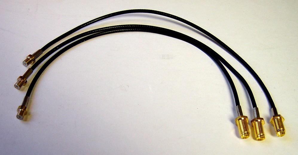
I used RP-SMA crimp-on connectors for RG-174 cable that I purchased in bulk from an Asian seller on a popular auction site, since you need three of each type. They can also be purchased from the major parts supply houses. I tried to use RG-58 like the originals but the cables were too stiff to use with SMA and modified SMA. The smaller coax is much more flexible and easier to use. Each extender cable needs to be about a foot long to allow room to work with the module. The excess will drop down between the other boards. Here's a photo of three RF cables made with RG174. Each cable measures 9-7/8 inches long end-to-end.
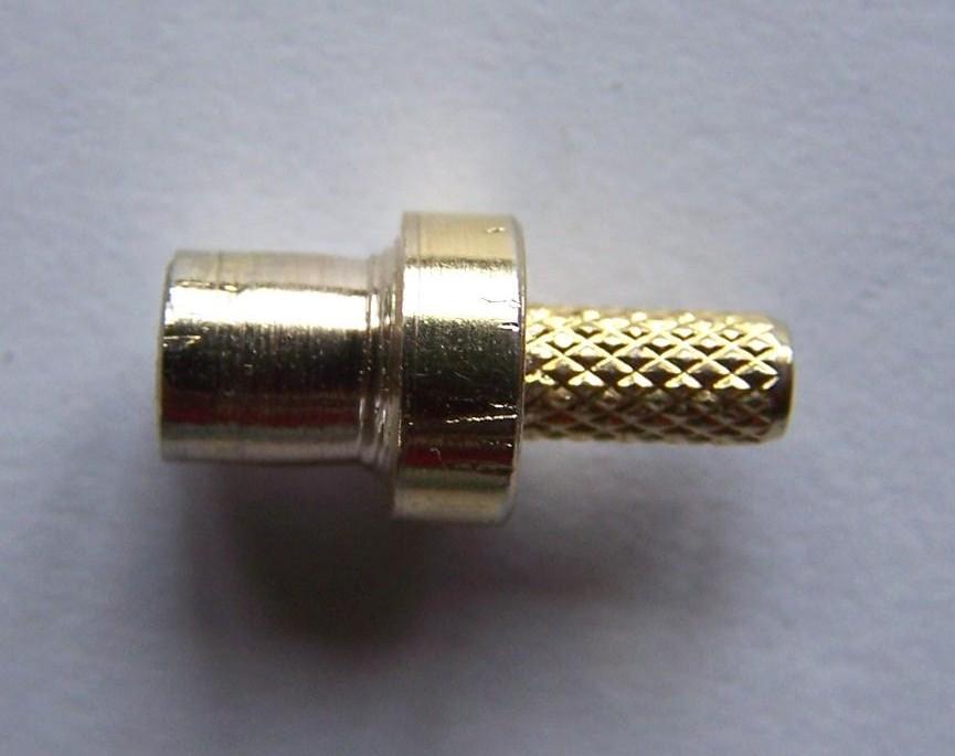
Here's a close-up photo of the business end of the RP-SMA connectors.
The cables will need a non-conductive (insulated) brace about four to six inches long attached to the female end to allow you to plug and unplug it from the motherboard connectors deep within the card cage; a thin piece of wood or plastic will be fine. You need this because you can't reach them with your hand without removing several adjacent cards. The OEM extender cables with OMQ connectors had multiple lengths of heat shrink on them so they were stiff enough to be plugged and unplugged. The Motorola instructions state "...to remove the RF cable, pull the sleeve of the connector away from the module. Do not pull on the cable to remove it."
As an alternative, pulling both the A4 and A5 modules will give you plenty of room to plug the cables in. So far I found it best to plug it in by pushing on the coax and remove it by pulling on the connector. This keeps the pins well seated.
Modifying the RP-SMA male body:
The center piece metal diameter is about 0.181 inch per the specification. The interior diameter of the OMQ female on the motherboard is about 0.174 inches. The gap from the top edge of the female to the insulation is about 0.149 inches. I found that a center diameter of 0.172 inches will fit all the connectors on my motherboard. A slightly larger 0.173 inches fit all but one.
I first tried swedging the nose of the SMA male using a hole drilled with a #17 bit with the top edge broken with a rose head reamer. This created two problems: the center pins marginally touched and the center hole in the insulation had to be reamed back to its original size.
Remove the retaining ring. I found it is soft so small pliers holding across the connector and bending out one side worked well. You won't need it again.
I used a small HF lathe to reduce the diameter with files steadied on a tool rest.
I used a C16-ER20A-100L collet holder in the 3-jaw chuck. The 3mm collet worked fine. You can get the complete collet set for about the cost of three or four individual collets. Check on-line auctions from Asia.
A file was sufficient to remove the band below the retaining ring and the few thousandths of material from the outer edge of the SMA body. The tail-stock would center itself in the insulation; not a good thing. Without the tail-stock support a lathe tool ended up pushing the brass connector away without removing any metal. I am NOT good using a lathe so someone with experience is probably having a good laugh right now.
An alternative is a drill press using a vise on the table as a point to rest the file. The photo below shows the slightly reduced size SMA body.
If you don't have the proper crimping tool, or don't want to make your own cables, you could buy some short SMA Male to SMA Male cables and attach an SMA Female to RP-SMA Male adapter at one end and an SMA Female to RP-SMA Female adapter at the other end. These are available on a popular auction site for about $3.50US each. The female will work without modification. The male RP-SMA adapter will need the same modification as the crimp connector.
We were told somewhere along the way not to stress the motherboard sockets, so use something to support the modules when you extend them. The analyzer in its normal position with the cards out the top is best for the heavy A4 and A5 cards. Use a prop board behind those to hold them for adjustments and in front something about 1/2 inch thick and about the same height and width as the extender card will stabilize the module and keep pressure off the RF jumper cables.
Contact Information:
Steve can be contacted at: his-callsign [ at ] arrl [ dot ] net.
Bob can be contacted at: his-callsign [ at ] comcast [ dot ] net.
Back to the top of the page
Back to Moto Test Equipment
Back to Home
This web page created 04-Oct-2017
This web site, the information presented in and on its pages and in these modifications and conversions is © Copyrighted 1995 and (date of last update) by Kevin Custer W3KKC and multiple originating authors. All Rights Reserved, including that of paper and web publication elsewhere.