Back to Home
Power Supply Capacitors on
the Motorola R2001B and R2001C
Communications Service Monitors
By Robert W. Meister WA1MIK

|
Back to Moto Test Equipment Back to Home |
Replacing the Screw-terminal Power Supply Capacitors on the Motorola R2001B and R2001C Communications Service Monitors By Robert W. Meister WA1MIK |
|
Background:
I previously (2016) replaced all the electrolytic capacitors on the circuit boards in the Low-Voltage Power Supply (LVPS) and High Voltage Power Supply. There were two large screw-terminal electrolytic capacitors mounted on the LVPS chassis that I decided not to replace, primarily because I thought they were good enough and because they were expensive (about $25 each).
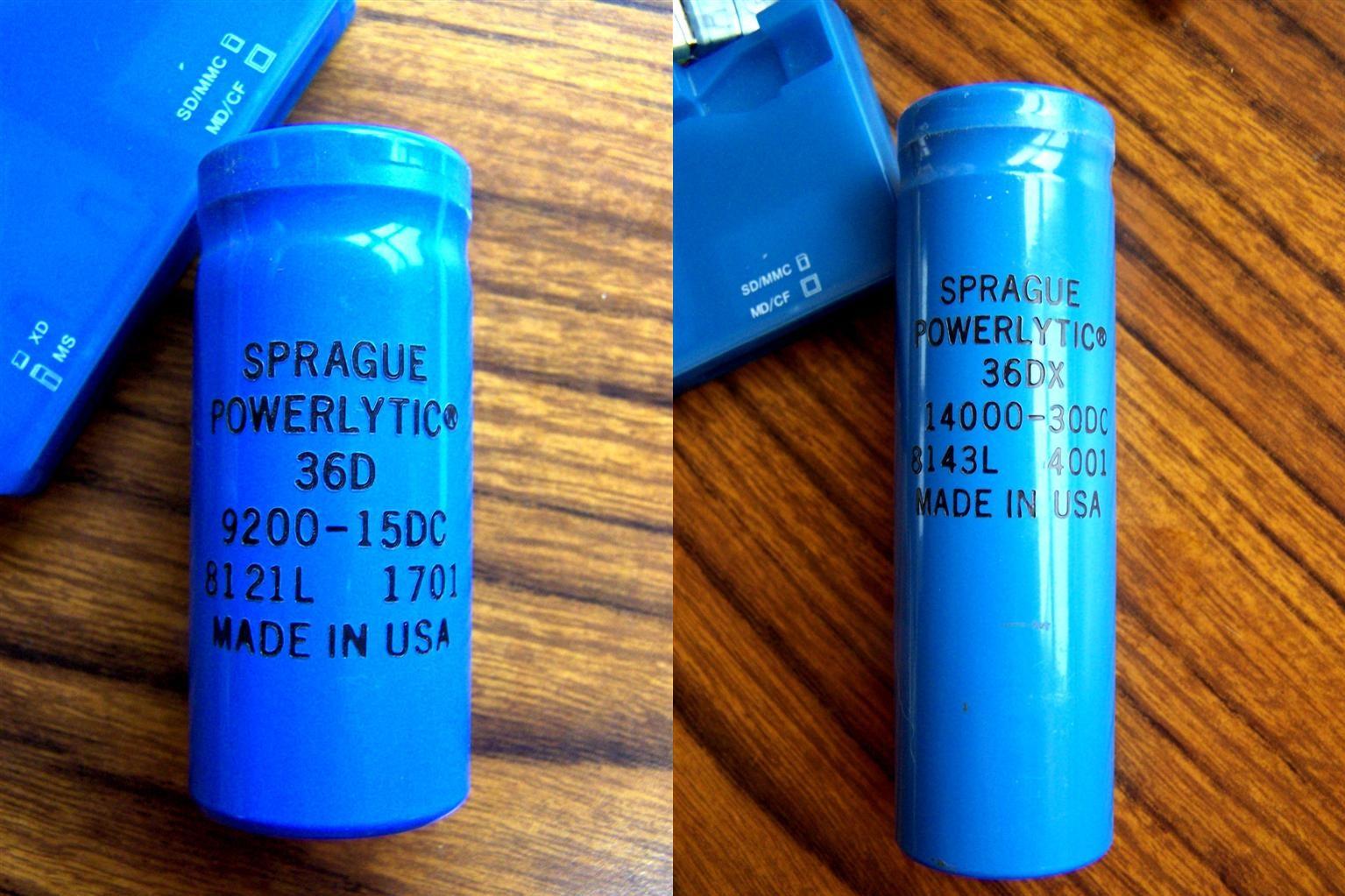
Original Caps:
The existing screw-terminal caps are mounted with the negative screw terminal attached to the chassis. The positive terminals go to round crimp lugs on wires that run into the LVPS A1 circuit board.
Steve (K7LJZ) and I recently measured the AC and DC voltages across these two caps and I was disappointed to see that one of mine had more AC voltage across it than I felt was acceptable. We decided to replace these caps because he had a unit that needed them as well. Between the two of us we agreed on suitable replacements. The table below describes the original parts. Both are 1.375 inches in diameter and 4-5 inches tall.
| Part | Original | Original | Meas. | Meas. | Noise |
|---|---|---|---|---|---|
| Desig. | uF | DCV | DCV | Vp-p | Component |
| C102 | 14,000 | 30 | 16.03 | 1.5 | 60 Hz sawtooth |
| C105 | 9,200 | 15 | 9.88 | 0.9 | 42 kHz spikes |
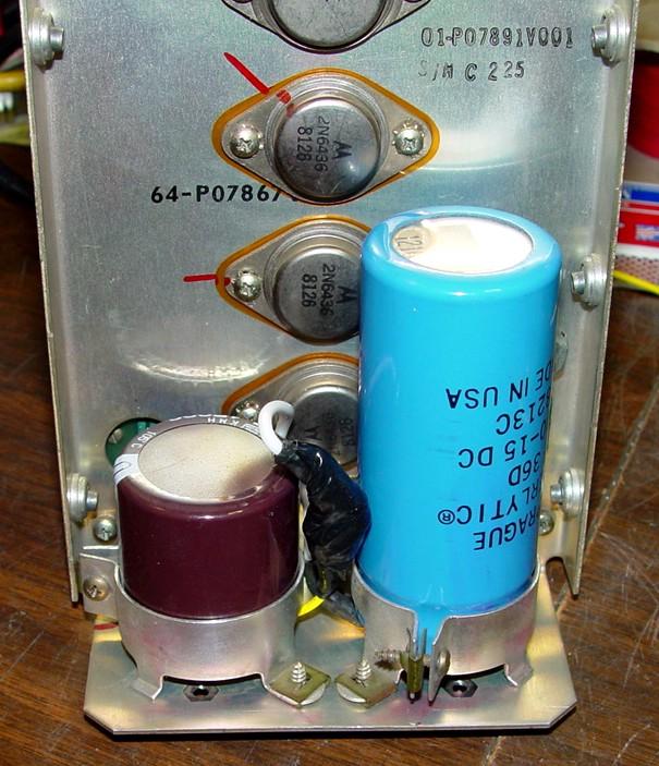
C102 is the taller of the two. C105 is located closest to the rear panel of the service monitor. For comparison, Steve's capacitor voltages were 14.85VDC, 0.04Vp-p and 10.4VDC, 0.4Vp-p. The photo below was provided by Steve K7LJZ. Click on it for a larger view.
New Caps:
New capacitors were originally selected from Digikey but when I went to order them, they didn't have one in stock, so I switched to Mouser and selected two others. These 105C snap-in capacitors are also 1.375 inches in diameter and have 10mm lead spacing. They cost about $4 each. They are much shorter than the originals (under 1.5 inches) but they fit into the existing mounting clamps.
| Part | New | New | Meas. | Meas. | New Mouser |
|---|---|---|---|---|---|
| Desig. | uF | DCV | DCV | Vp-p | Part Number |
| C102 | 15,000 | 35 | 16.02 | 1.5 | 661-EKMH350VSN153MA3 |
| C105 | 10,000 | 25 | 9.87 | 0.8 | 598-LP103M025H3P3 |
You may notice that there was no improvement with the new capacitors installed, which means my original screw-terminal capacitors were actually working quite well, but who knows for how long. I did measure the originals after I removed them: C102 was 15,300uF, C105 was 10,970uF.
The plan is to add short wires with round crimp lugs to each of the snap-in capacitor terminals. The negative terminal will go to the ground screw hole that was used on the original screw terminal capacitor and secured with a new screw and nut. The positive terminal will get spliced with a #8-32 screw and nut to the existing positive round crimp lugs then wrapped with electrical tape. I wanted to use #10-32 hardware but found out the biggest I had was #8-32, so I used that. I purchased some round crimp lugs for #10 screws with internal lock-washer teeth for #18-22 wire for about $0.15 each, Mouser part number 538-19074-0007.
Replacement Procedure:
To remove the LVPS, remove both the top and bottom covers from the unit. Turn the unit on its right side. From the bottom, carefully unplug all four cables from the bottom of the LVPS. You might want to insert the DIP plugs into some foam and tape them up, to protect them from damage. There's one coax cable with an RCA plug on it that may get in your way; unplug that from the back of the RF Attenuator (A11) assembly. Remove the six screws on the rear panel, located around the fan, securing the LVPS to the chassis. You do not have to remove the fan. Support the LVPS as you remove the last screw, as it will fall towards the right side of the unit. With the supply sitting on the right side of the unit, slide it out from the bottom. Here's a photo showing the original capacitors in my supply.
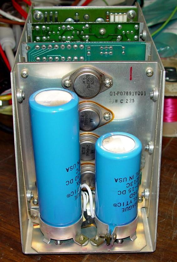
Remove the A1 card; that's the one with the two screw terminal capacitors on it. Remove one flat-head screw from the rear-facing side of the LVPS chassis and two flat-head screws from the other side of the LVPS chassis. Remove two round screws with washers from underneath the chassis. The A1 card with the two screw-terminal capacitors can then be pulled straight up and out of the chassis. See the photo below.
Work on one screw-terminal capacitor at a time. Unscrew both terminals from the chassis under the power supply, loosen the clamp screw, and pull the capacitor straight out. Retrieve any loose hardware. There is a spacer on the ground screw and some washers on the other one. Since we're only replacing one capacitor at a time and only one round crimp lug goes to each capacitor, you don't have to mark anything. Note that the ground screw hole is smaller than the access hole for the positive screw and further towards the sides of the LVPS chassis. Remove the two small screws holding the capacitor clamp to the chassis, as it will make the rest of the procedure a lot easier. I didn't do that when replacing the first cap.
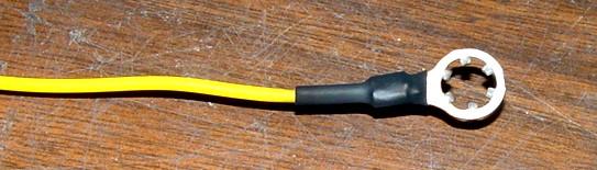
Cut two 3-inch pieces of #20 insulated stranded wire. Crimp and solder a #10 round crimp lug to one end of each wire. Strip and tin the other ends. If you have some, apply heat shrink tubing over each of the crimped joints. See the photo below.
Connect the crimp lug on one of the above wires to the positive lug coming from the LVPS using a short (1/4 inch long) #8-32 screw and nut. Tape and insulate this joint well with at least five full wraps of electrical tape.
Using a short (1/4 inch long) #8-32 screw and nut, secure the remaining wire's crimp lug to the #10 ground hole that was previously occupied by the screw-terminal capacitor's negative screw. Orient the ground lug so it points towards the A1 card and away from the neighboring larger hole. Place the capacitor clamp over that area and make sure the ground wire doesn't obstruct the clamp. The photo below was taken before I taped the splice, to show the details. Click on it for a larger view.
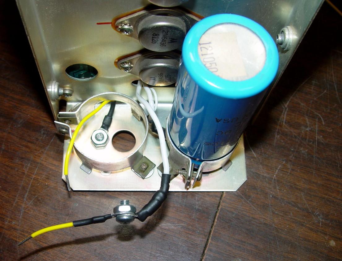
Solder the two wires to the capacitor's two terminals. The ground wire goes to the capacitor's negative terminal, which is adjacent to the vertical band on the outside of the capacitor. The spliced wire goes to the capacitor's positive terminal.
Flip the capacitor so the terminals face down, and slide the capacitor clamp over the new cap and secure it in place. You may have to re-orient the ground lug so it clears the clamp. The wires will end up under the edges of the capacitor clamp, just like they did originally.
Slide the new capacitor, terminal-side down, into the clamp, moving the wires as you go. Align the capacitor so its positive terminal is accessible through the hole in the LVPS chassis and verify that nothing else is near this terminal then tighten the clamp screw. The new cap's ground terminal can contact the ground screw but make sure the ground lug does not interfere with the positive terminal. This will allow you to carefully probe the capacitor's positive terminal later for metering purposes. Stuff the spliced and taped positive joint anywhere behind or next to the new cap where it won't interfere with anything. See the photo below.
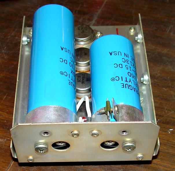
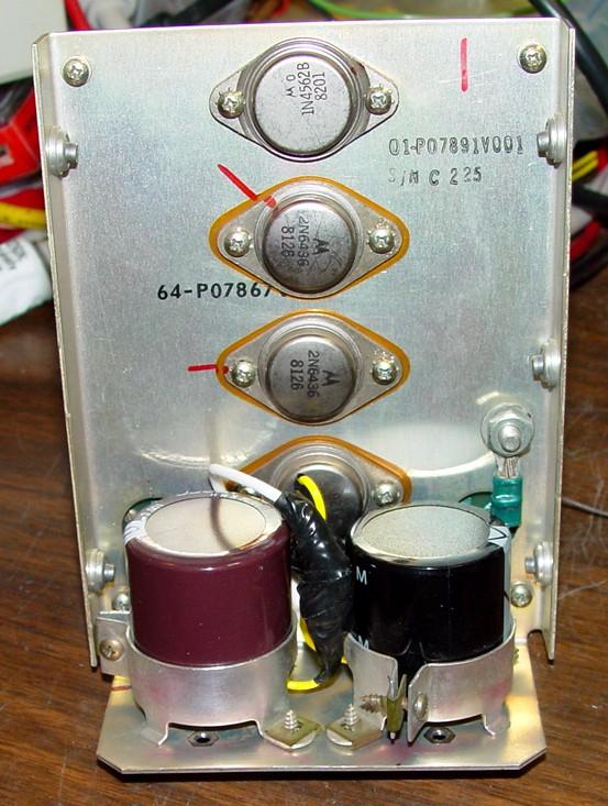
Repeat this procedure with the other capacitor. Here's a photo showing the completed capacitor replacement.
Use an ohmmeter and verify that the positive terminals of the new caps aren't shorted to the chassis. You can access those terminals through the holes under the capacitors.
Reinstall the A1 card into the LVPS chassis and reinstall the LVPS into the unit. No adjustments should be required if your unit was working properly before you replaced these capacitors, otherwise you should verify the +5V test point and adjust if necessary.
Acknowledgements and Credits:
Steve K7LJZ supplied photos of the original screw-terminal capacitors in one of his R2001B service monitors.
DC voltages were measured with a Fluke 189 digital multi-meter.
Peak-to-peak voltages were measured with a Tektronix 453 oscilloscope.
Contact Information:
The author can be contacted at: his-callsign [ at ] comcast [ dot ] net.
Back to the top of the page
Back to Moto Test Equipment
Back to Home
This article created 26-Jan-2020
This web site, the information presented in and on its pages and in these modifications and conversions is © Copyrighted 1995 and (date of last update) by Kevin Custer W3KKC and multiple originating authors. All Rights Reserved, including that of paper and web publication elsewhere.