Back to Home
Communications Systems Analyzers
By Steve Goggans K7LZJ

|
Back to Moto Test Equipment Back to Home |
Repairing the Motorola R2001-series Communications Systems Analyzers By Steve Goggans K7LZJ |
|
There seems to be a dearth of repair information on the Motorola R2001 any suffix power supplies.
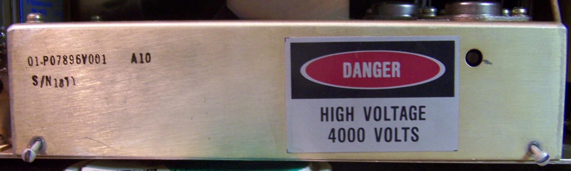
LV Power Supply part number 01-P07897V001 (A1) and HV power Supply 01-P07896V001 (A10) are used in R200x B and C series. NO relation to the D series.
This adventure started with the purchase of a smoked R2008C to get a replacement CRT for the dim fuzzy CRT in the R2002B I got at Dayton 5 or so years ago.
I just had to try fixing the C before I started pulling parts. The LVPS was bad and blowing line fuses.
The GREAT news is the R2002 CRT was just fine. After recapping and adjusting the LVPS and HVPS the old dim fuzzy CRT is BRIGHT and CRISP!
The "working" B LVPS was used for comparison and board swaps during troubleshooting. A lot of bad caps were discovered in the B supply by accident.
The low voltage power supply description says the switching power supply operates at 20 kHz. The operating frequency is set by R330 and C318 and both are fixed. The schematic value of R330 is 22K and is out of design range according to the MC 3420 data sheet value range of 5K to 20K. According to the data sheet nomogram, the values should be C318 0.002uF and R330 13K for about 20kHz - if you really care. AND what to my wondering eyes should appear on A1A3 boards in both supply boards R330 is a 13K metal film and C318 is 0.002uF. Correct your print. I tried substituting a 25K 20T pot for R330 and varied the switching frequency from 20kHz to 27kHz. If there was any difference it favored a higher frequency. Dead Time, Voltage and HVPS adjustments change with frequency. My take is I wasted my time!
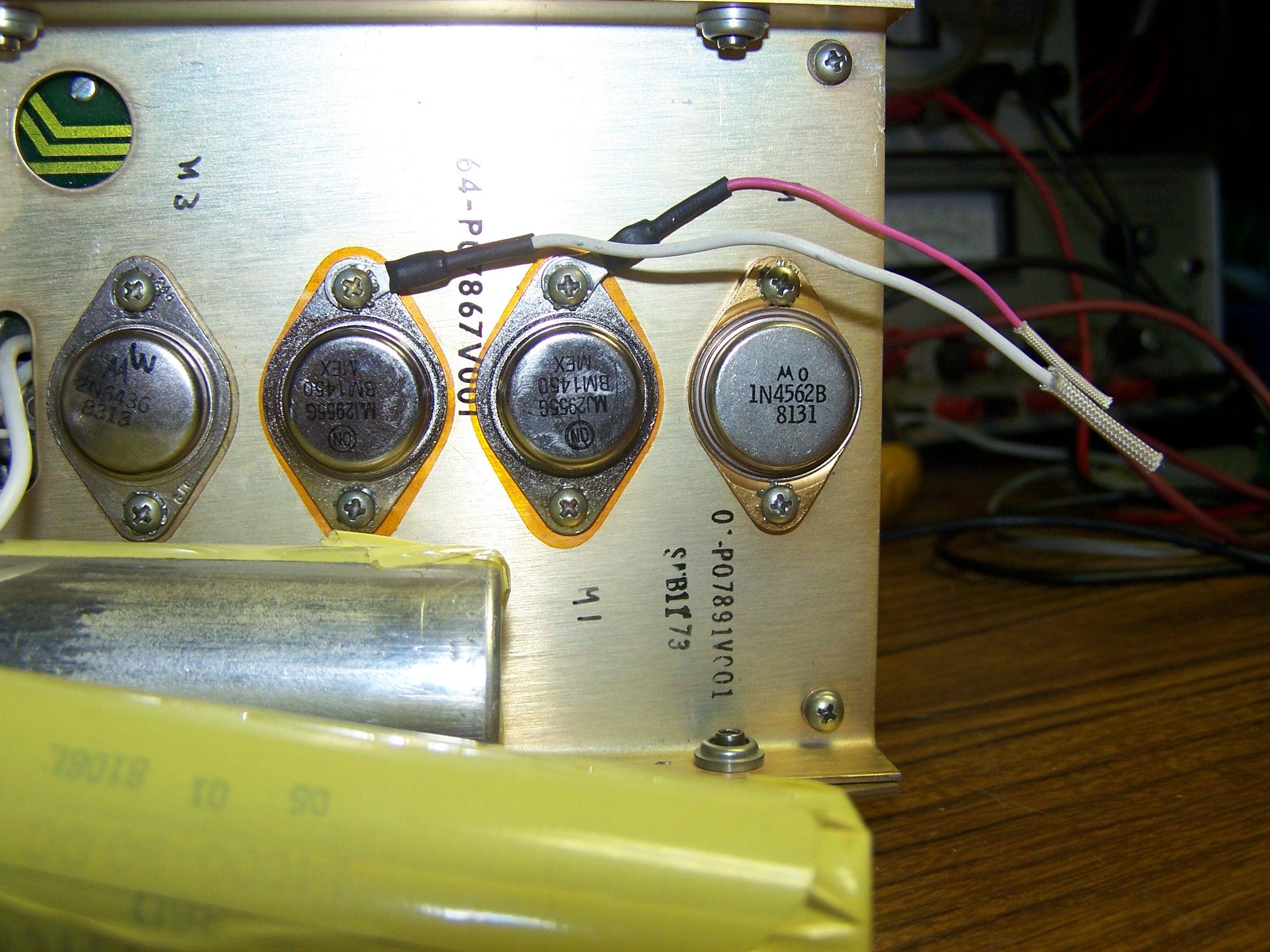
First problem found was two out of three 2N6436 on A1A1 were blown: Q102 and Q104. Resistor R102, the base resistor for Q102, was cooked and is probably where the magic smoke came from. I tried many different audio and switching transistors to replace the unavailable 2N6436 before WA1MIK led me to the 2N6437, a higher voltage part that's otherwise identical to the 2N6436, and it IS available new (BOCA Semiconductor) on eBay. DON'T waste your time with anything else; get the BOCA 2N6437. While it seemed likely that almost any transistor would work at 20kHz switching frequency, they DON'T; in most cases they're not even close.
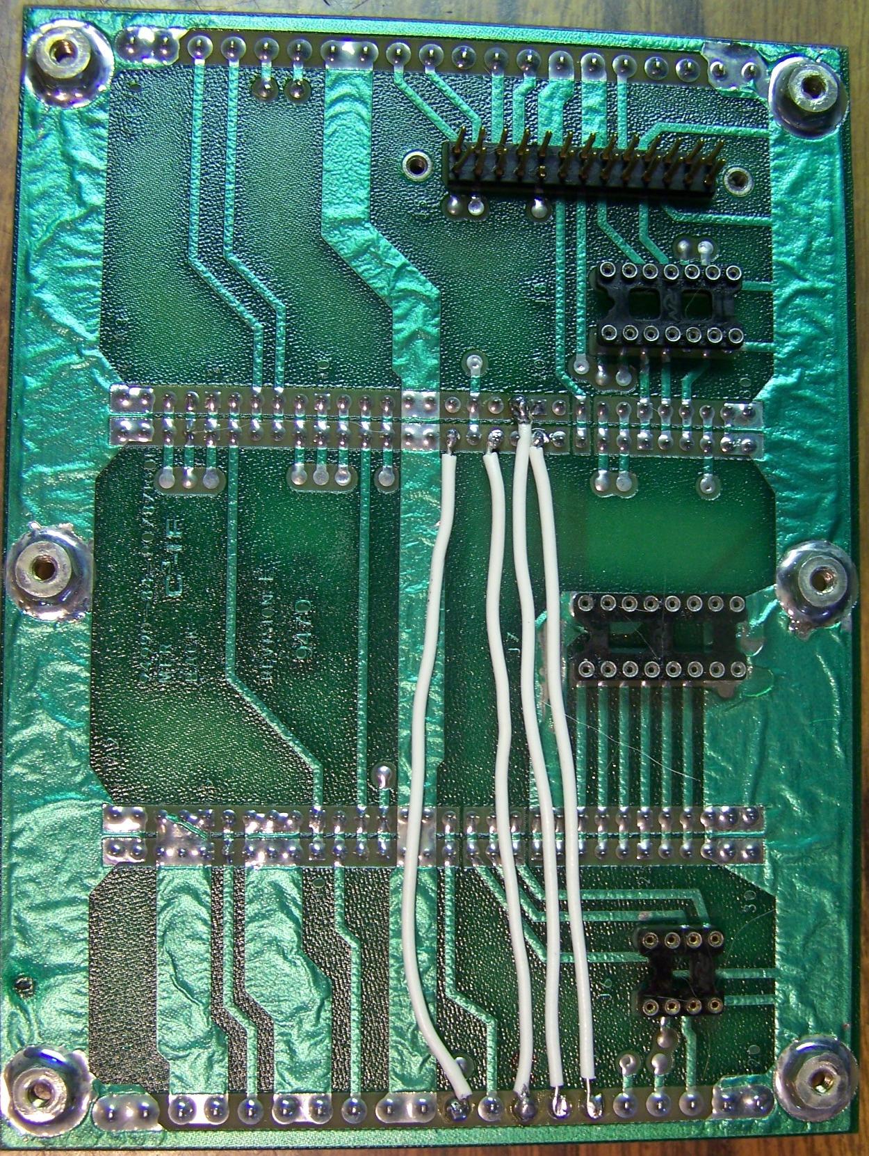
At this point the R2008 cards would work in the R2002 frame so the 2008 power supply motherboard was suspect. It was pulled and looked over. Nothing looked out of normal so back together again. It kept looking like PWM drive TP302 was not making it to A1A1 Q101 base. Finally I popped the power supply motherboard again and started measuring between connectors even though the traces all looked fine. The trace from A1-13 to A3-18 PWM DR was open even though it looked fine. Bright light and tipping the card revealed that the trace width under socket for A1A2 is extremely thin and was burned open. Also A1-14 to A3-19 Chopper DR B was intermittent. LESSON: If a power transistor on A1A1 board blows it may pop one or more traces under the A2 socket on the power supply motherboard. I added wires for the 4 traces on the back of board. Click on any photo for a larger image.
Dead Time Pot:
The Dead Time pot gets adjusted watching the waveform on Q103 and Q104 (see photo below) for just less than a sharp shoulder. Keep a close watch on the transistor temperature by laying a finger over them. Too far CW and they get HOT FAST! Back off the Dead Time pot CCW 5 to 10 degrees. On the scope trace, both channels are set to 5V/Div and the time base is set to 10uS/Div.
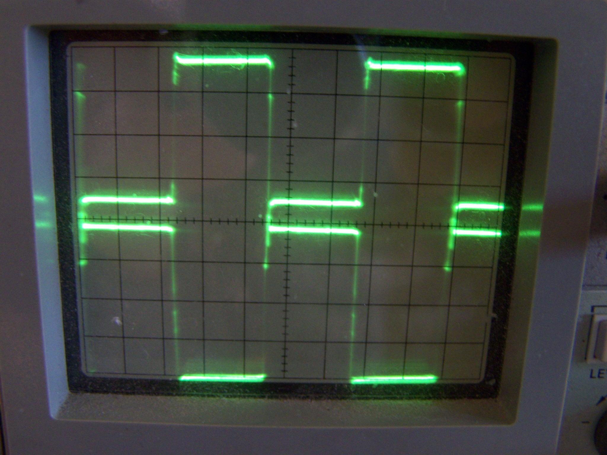
This is used to prevent the inverter switching transistors from cross-conducting at high duty cycles. In the repaired 2008 it was used to set the collector traces of Q103 and Q104 as mirror images while monitoring transistor case temperature with a finger.
In the R2002 supply it also makes a major difference in the CRT intensity and focus, so set it for the best display, Q103 and Q104 are also nice mirror images. The TO-3 cases run warm, not HOT.
Further experimenting finds the original Q103 and Q104 are quite forgiving for the setting of Dead Time.
Helpful Modification:
Board A1A3 "Dead Time" range resistor in front of pot R328 is R340: change 3.9K to 4.7K.
Test and Setup Notes:
The saw tooth on TP 205 reads twice the frequency on a Fluke 87. The 2002B frequency is 21.72 kHz on TP306 and TP307. The 2008C frequency is 22.39 kHz on TP306 and TP307. These frequencies are in the ballpark for the actual parts used on the boards.
Current limit pot: turn CCW till current limit starts toggling and then back CW a bit, maybe 15 degrees. Have experienced no problems and had accidental short with test lead in PS just caused the PS to cycle off and back on.
While the supply was out I recapped most of it and measured the removed caps. Some were open, some were leaky and some were OK. One had a broken lead. Well worth the effort. Ground leads are difficult to get out of the boards, as the solder on the topside foil is well heat-sinked. I used a Pace on the non-ground leads then a soldering iron on the ground one and pulled it out leaving the solder in the hole. Soldering iron on top of board and Pace on bottom cleaned them out for installation of new caps.
Along the way I found CR204, one of the Schottky diodes in the 5V supply, was almost totally shorted - easy to see on a Huntron Tracker and also the diode readings on a Fluke 87 were much different than a good one.
The PWM chip MC3420 seems to be a one off - no replacements. There are no other PWM control chips with dual outputs. The data sheet only addresses values of "Dead Time" values with a voltage on Pin 6 Vcontrol and in this application has Pin 6 grounded.
HV Supply:
High Voltage supply A10 has 3 electrolytics. The supply is easy to remove. Unplug the HV lead from the front of the CRT. Gently rock and pull the CRT socket. Remove the ground lead from the CRT center clamp. Remove the 5-pin plug from the scope deflection board A2 to the CRT socket.
Go to other side of chassis and unscrew the two captive screws on the bottom of the chassis by main chassis. It takes more time to read than do.
The card edge plug slides apart as you carefully pull the supply out and thread the plugs and CRT socket through chassis. Lube plugs and sockets with Nyogel - makes plugging in CRT socket a breeze.
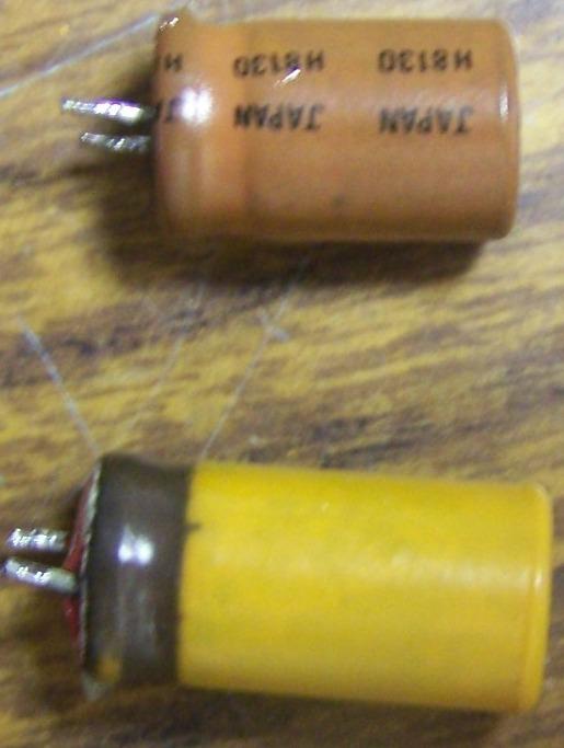
R2008C caps were close and slightly leaky, R2002B C17 OK, C15 LEAKY orange wrap brown and PC board discolored, C21 open - bottom 1/4 inch of orange (photo looks yellow) plastic wrap is black. Note the red seal on the bottom of the bottom capacitor with the brown ring in the picture. This is one of the infamous "No Name" red sealed caps that you REALLY want to replace. Most of the "No Name" red bottom caps I found were clear plastic wrapped and say USA on the side.
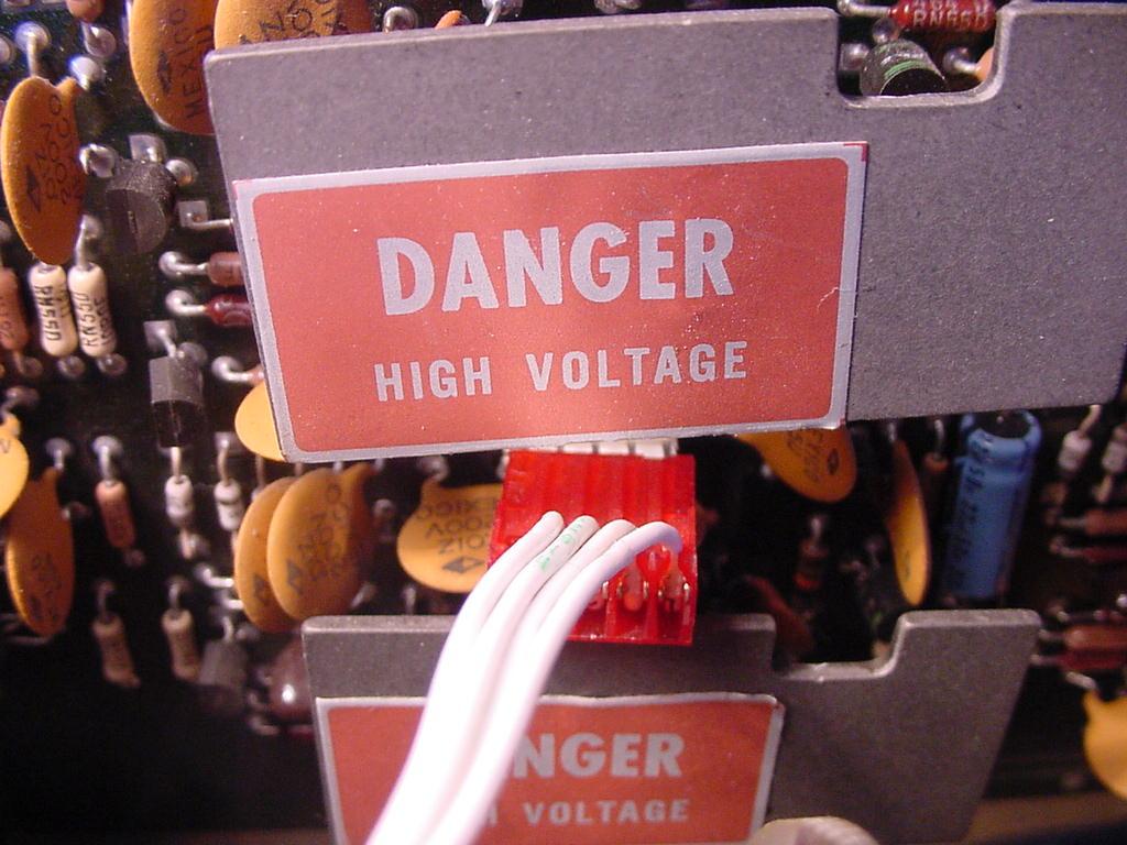
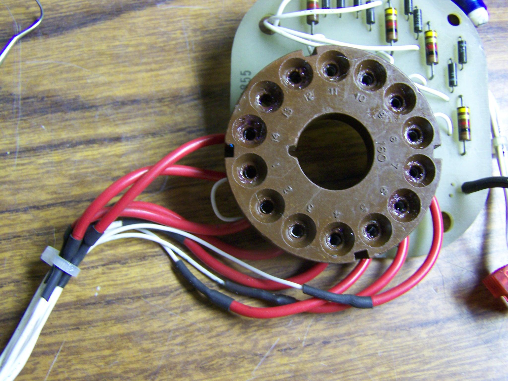
The wires connecting to the CRT socket started breaking at the solder joint on one unit. Using an extender board is much easier if the wires are a few inches longer so some flexible wire extensions were added to solve both problems. The white ground wire on the socket had only a few strands unbroken and was replaced with a flexible black wire seen leaving the lower right corner of the picture.
General tips:
Other Repairs:
Note: The front panel comes off with all the knobs and switches as an assembly and ribbon cables unplug from the main board. CRT center bracket needs to be loosened and tube socket removed to slide front forward. A few wires need to be unsoldered from the motherboard depending on how far you need to remove the panel. Use caution with the flex connector cables that damage easily.
Print Errata Not Noted Above:
Low Voltage Output A1A2 Schematic: L203 lead going to R203 has been pulled out of board and a 1N4001 added in series cathode to board. L204 lead going to C213 has been pulled out of board and a VSK520 Schottky added in series cathode to board.
Low Voltage Control A1A3 REV E Schematic: Pot R313 is 10K not 5K.
HV PS (A10) J1 pin 4 to LVPS J6 pin 3 goes to GND on LVPS MB. NOTE: HV PS J1 Pins 1 and 4 not tied together on HV PS.
Notes:
Nyogel 760G I was told by one of the factory product service engineers from a previous life, that it was developed by or for Nissan racing to solve intermittent connector problems. We used it on low-level signal connectors and card edge connectors in industrial control systems to make intermittent gremlins disappear. This is one of the products that lives up to its website hype. It was used on ALL the card edge connectors, plugs and sockets including the CRT - no more gremlins.
A few cross reference part numbers found along the way:
Test Points from two working units taken with a Fluke 87. Power switch ON and warmed up and TP202 adjusted for 5.2VDC.
| TP | R2002B Boards Recapped | R2008C Boards recapped and Freq set to 22 kHz |
|---|---|---|
| TP101 | 10.61 VDC, 6.94 VAC 43.5 kHz | 10.13 VDC, 6.5 VAC 44 kHz |
| TP102 | 15.26 VDC, 0.76 VAC 21 kHz | 14.5 VDC, 0.87 VAC 19.5 kHz |
| TP103 | 14.48 VDC, 0.79 VAC 21 kHz | 14.2 VDC, 0.88 VAC 20.5 kHz |
| TP201 | 0 | 0 |
| TP202 | 5.2 VDC, 1.5 mVAC Adjust to 5.2V | 5.21 VDC, 4 mvAC Adjust to 5.2V |
| TP203 | -4.97 VDC, 1.9 mVAC | -4.91 VDC, 4 mvAC |
| TP204 | 12.95 VDC, 1.8 mVAC | 13.15 VDC, 4 mvAC |
| TP205 | -13.00 VDC, 1.8 mVAC | -13.40 VDC, 4 mvAC |
| TP206 | 34.7 VDC, 2.7 mVAC | 34.4 VDC, 4 mvAC |
| TP207 | 122.2 VDC, 15 mVAC | 117.9 VDC, 12 mvAC |
| TP208 | -121.8 VDC, 7 mVAC | -117.9 VDC, 11mvAC |
| TP301 | 8.02 VDC, 4.4 mVAC | 7.94 VDC, 4 mvAC |
| TP302 | 15.64 VDC, 0.55 VAC | 14.95 VDC, 0.64 VAC |
| TP303 | 5.03 VDC, 104 mVAC 38 kHz | 5.08 VDC, 100 mV 44 kHz |
| TP304 | 12.81VDC, 73 mVAC 21.8 kHz | 12.77 VDC, 36 mV 44 kHz |
| TP305 | 4.14 VDC, 1.08 VAC 43.6 kHz | 4.12 VDC, 1.07 V 44 kHz |
| TP306 | 5.97 VDC, 4.8 VAC 21.8 kHz | 6.12 VDC, 4.54 V 22 kHz |
| TP307 | 5.99 VDC, 4.8 VAC 21.8 kHz | 6.13 VDC, 4.54 V 22 kHz |
| TP401 | 15.94 VDC, 0.51 VAC 120 Hz | 15.17 VDC, 0.61 VAC |
| TP402 | 0 | 0 |
| TP403 | 15.32 VDC, 0.51 VAC 120Hz | 14.38 VDC, 0.603 VAC |
| TP404 | 0 | 0.51 VDC, 55 mvAC - oven at temp for several days |
Contact Information:
The author can be contacted at: k7lzj [ at ] arrl [ dot ] net.
Back to the top of the page
Back to Moto Test Equipment
Back to Home
This web page created 04-Apr-2016
This web site, the information presented in and on its pages and in these modifications and conversions is © Copyrighted 1995 and (date of last update) by Kevin Custer W3KKC and multiple originating authors. All Rights Reserved, including that of paper and web publication elsewhere.