Back to Home
Communications Service Monitor
RF Input Protection Fuse Analysis
By Steve Goggans K7LZJ
with help from Robert W. Meister WA1MIK

|
Back to Moto Test Equipment Back to Home |
Motorola R20XXD-series Communications Service Monitor RF Input Protection Fuse Analysis By Steve Goggans K7LZJ with help from Robert W. Meister WA1MIK |
|
The R20XXD service monitors have a separate RF Input BNC jack with an integral fuse that protects the more delicate front-end components inside the unit. The fuse holder is actually a two-piece adapter terminated with an SMA-female behind the front panel. The front BNC piece unscrews from the chassis adapter section and the fuse fits inside the two parts. It seems that fuse holders like this are no longer manufactured.
We thought this fuse was a standard Littelfuse 251 or 253-series PicoFuse rated at 1/16 amp and 125V. These are green epoxy-coated fuses that are currently about 0.110 inches in diameter according to the datasheet. They used to be a bit thinner, as small as 0.090 inches in diameter, but seem to have grown somewhat over the last 30 years. We have since determined that the 265 or 275-series are what were used. These have a piece of clear tubing over the fuse body and an outer diameter that is around 0.093 inches. Further checking determined that they were rated for 1/8A.
The cavity inside the BNC jack is only 0.095 inches in diameter. See the diagram below. The letters are measurement points and will be explained in the text below the drawing. Click on any image or photo for a larger view.
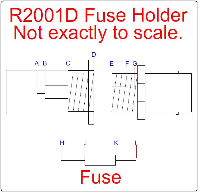
For the left (chassis) portion we have the following dimensions (in inches).
| From | To | Meas. | Notes |
|---|---|---|---|
| A | D | 0.500 | |
| B | D | 0.383 | |
| C | D | 0.220 | |
| A | B | 0.117 | Lead Length |
| B | C | 0.163 | Fuse Length |
| B | B | 0.095 | Fuse Diameter |
| A | A | 0.019 | Lead Diameter |
For the BNC (removable) portion, we have the following dimensions (in inches).
| From | To | Meas. | Notes |
|---|---|---|---|
| E | G | 0.240 | |
| E | F | 0.150 | Body Length |
| F | G | 0.090 | Lead Length |
| F | F | 0.095 | Fuse Diameter |
| G | G | 0.019 | Lead Diameter |
The fuse leads fit into the contact areas formed by A-B and F-G. The fuse body fits into the larger cylinder formed by B-C and E-F. The threaded portion of the BNC jack fits into the largest cylinder formed by C-D. Points D and E were used as the measurement reference point for each section.
The fuse itself is also shown on the above diagram. The maximum dimensions are listed below. You probably want to cut the leads about 0.010 inches shorter so everything fits without damaging the connector or the fuse.
| From | To | Meas. | Notes |
|---|---|---|---|
| H | J | 0.117 | Lead Into Chassis Part |
| J | K | 0.313 | Fuse Body Length |
| K | L | 0.090 | Lead Into BNC Part |
| H | L | 0.520 | Overall Length |
Cut both ends at a 45 degree angle to form opposite sides to get a wedge center. I used a jeweler's file to flatten the point and make a more cone shape with a flat point and no square edges. A sharp point could get between the outside of the contact's fingers and the insulator and destroy the assembly. Get the leads as straight to the fuse axis as you can. The close body tolerance will help get the lead centered as you assemble. A little Nyogel on one end and inserted it into the BNC end. I could tell when it slid into the center socket with minimal resistance once the Nyogel was applied. A little Nyogel on the chassis end and slowly screwed it in. I could barely feel the end contacting the chassis side socket and it screwed in with almost no resistance. Light Silicone grease would also work.
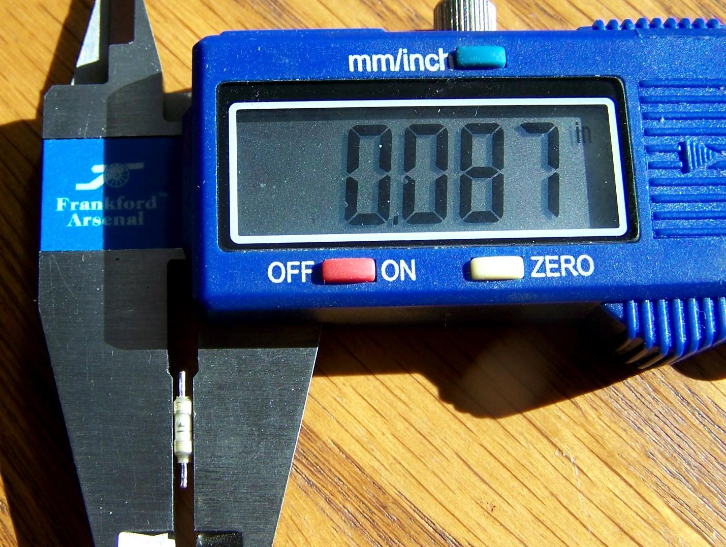
Here's a photo of a stock fuse showing its diameter. You can see the LF logo on the fuse body.
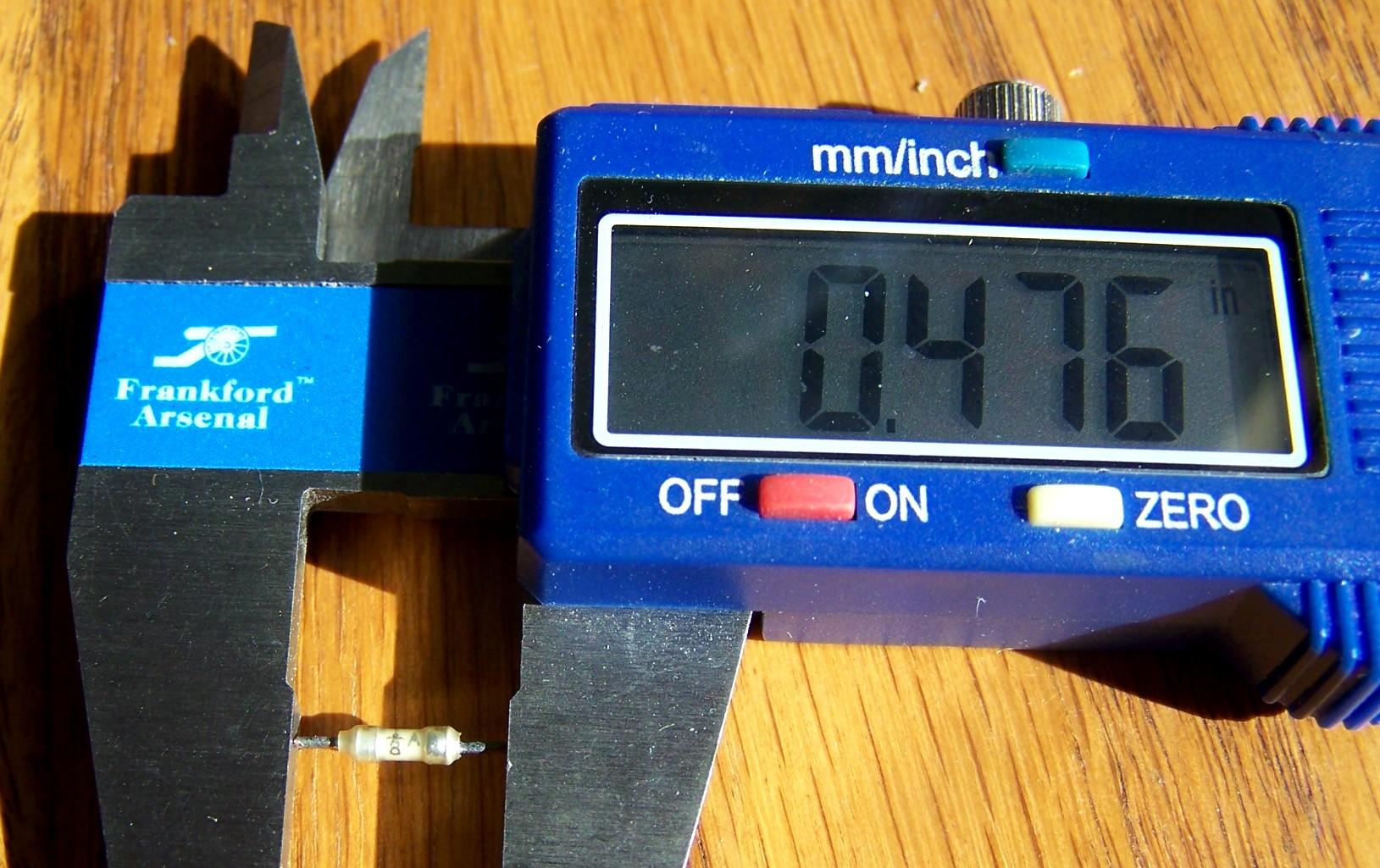
Here's a photo of a stock fuse showing its overall length. You can see the 1/8 amp rating (vertically) on the fuse body.
Adapter Photos:
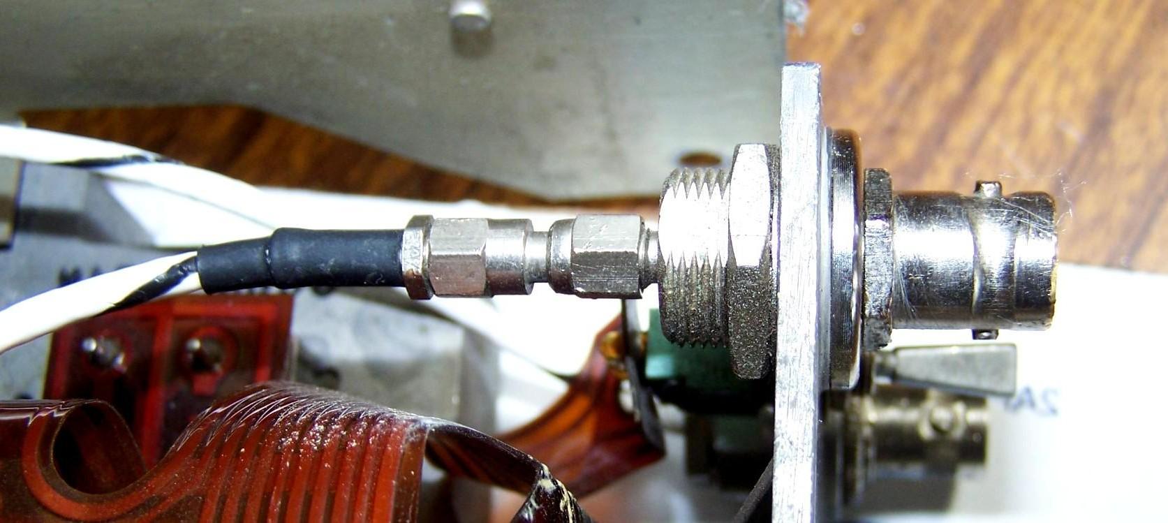
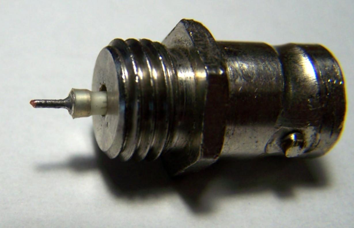
Here are some photos taken by Steve K7LJZ. First we have the entire fuse holder as installed in the R20XXD chassis with the BNC part that protrudes through the front panel on the left and the SMA part on the right.
Next is just the BNC part with a fuse still installed.
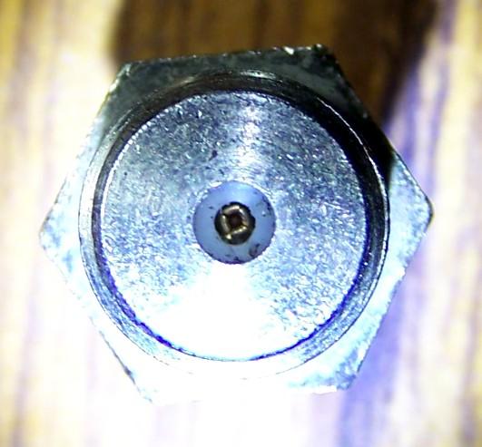
Next is a photo looking into the chassis portion, from whence we got the A-B-C-D dimensions.
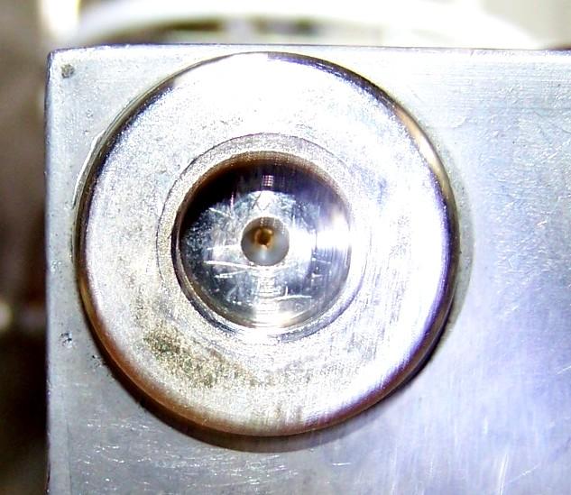
Then we have a photo looking into the BNC portion, from whence we got the E-F-G dimensions.
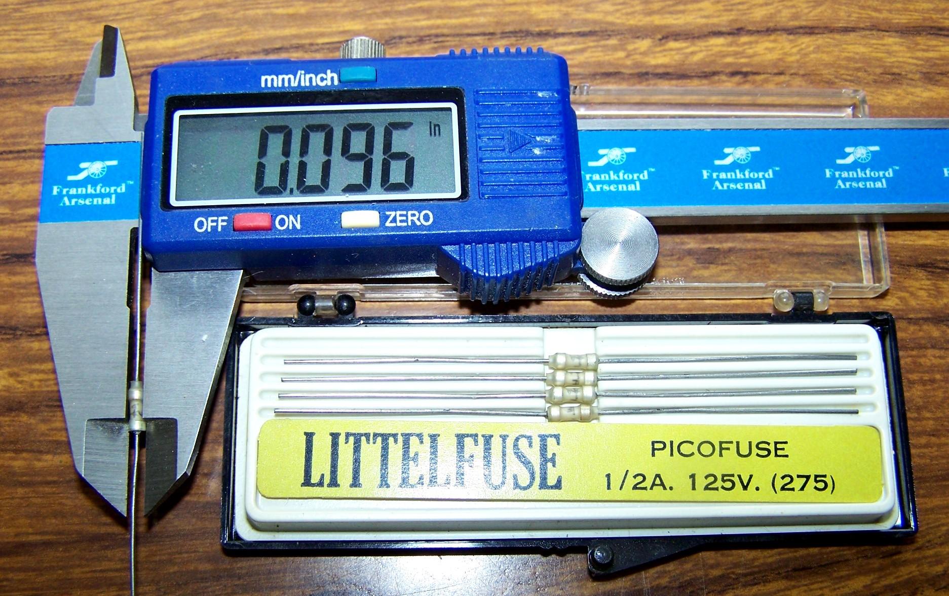
Lastly we have a micrometer measuring the diameter of a 275-series fuse.
The current Littelfuse 275-series datasheet only lists 20 and 30A values, however there are lower current fuses out there that are supposedly 275-series. You want the 275.062 fuse rated at 62.5mA or 1/16A.
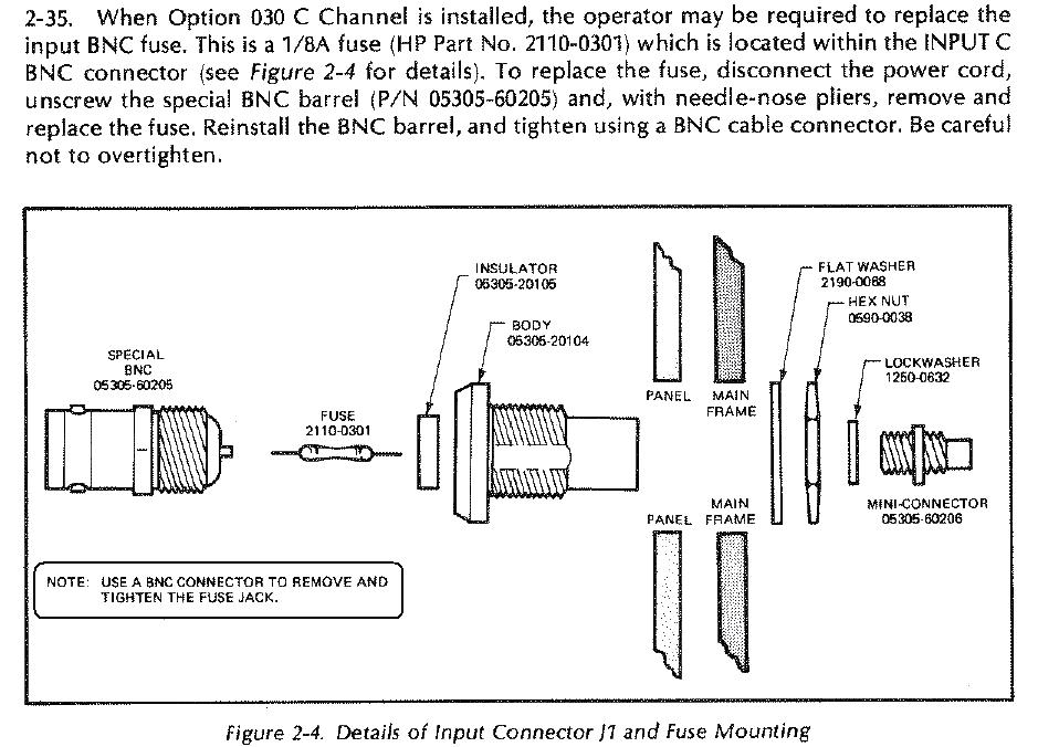
Several older Hewlett Packard (HP) frequency counters have a nearly identical fused BNC jack on their inputs. They use a 1/8A fuse. My HP-5385A counter has one and I removed and measured it. It's a very thin olive-green epoxy-coated Littelfuse Picofuse rated at 1/8A. The outside diameter was 0.092 inches and the total length was 0.78 inches.
I found a very nice drawing of the fuseholder in an HP 5335A counter manual, shown below. Notice that it tells you how to remove and reinstall the front BNC part. This particular connector has two flats that let you use an ordinary open-end or adjustable wrench to remove and tighten the front part. The same trick can't be used on an R20XXD BNC connector because it is covered up by the front panel assembly.
Contact Information:
The author can be contacted at: his-callsign [ at ] arrl [ dot ] net.
Back to the top of the page
Back to Moto Test Equipment
Back to Home
This web page created 24-Jan-2021
This web site, the information presented in and on its pages and in these modifications and conversions is © Copyrighted 1995 and (date of last update) by Kevin Custer W3KKC and multiple originating authors. All Rights Reserved, including that of paper and web publication elsewhere.