Back to Home
By Kevin Custer W3KKC
Edited by Mike Morris WA6ILQ

|
Back to the Kenwood Index Back to Home |
Repair of the Toshiba S‑AV17 (and similar) RF power modules By Kevin Custer W3KKC Edited by Mike Morris WA6ILQ |
|
Note from WA6ILQ:
The Toshiba S-AV17 is a 50 watt high band RF power module is
used in the Kenwood 241, 641, 642, 741, 742, 941, 942 and many
other radios. Clones of it are used in a large number
of other radios, both amateur and commercial (land mobile). I
have found that many of the newer Kenwood radios are being
shipped with absolutely none of the white heat sink
compound between the module and the heat sink (perhaps as a
cost cutting measure?). If you have the radio open
for some other reason you may what to check for that... The
RF power module is supposed to be heat sunk to the chassis and / or
the heat sink, but without any heat transfer compound it overheats
and warps, making what heat transfer there is even worse. Most of
the time the module lasts long enough to be out of warranty by the time
it fails. The failure mode is frequently a crack caused by
overheated substrate. Sometimes the crack can be repaired,
and this repair is the topic of this article. And before you reinstall
the repaired module, you might want to check the back side (the heat sink
side) for flatness, and maybe file it down a little. If you have access
to a milling machine, so much the better. The whole idea is that if the
module did warp a little that filing it flat will impreove the heat
transfer. And don't forget to use some of the good white heat sink
compound - just enough to fill the voids, and no more.
BTW, here's The Toshiba data sheet on the S-AV17.
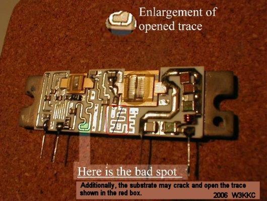
Photo by Tony Lelieveld VE3DWI
Kevin Custer W3KKC wrote:
I recently started having trouble with my Kenwood TM-742 that I
have in my work truck with not reliably putting out power on the 2
meter band. I have had this problem in the past and I always just
called up RF Parts Co. and spent the big bucks to get a new
module. I always check the two PIN diodes as these are sometimes
the cause of module failure (and receiver deafness). This
particular radio has had this module changed in the past, and this
time didn't have any PIN diode failure.
Someone posted to the Yahoogroups LMR list the ability to locate a surface fracture and hence the culprit of why the module makes no power. I decided to open the S-AV17 in my radio to see if this was the case in my module - I had nothing to lose as the module was dead anyway. I tested the transistors with the diode function of my Fluke DVM.... all read ok. The bases of the transistors are connected to ground via a choke (stripline type) so they will read a dead short to the emitter. Both of my transistors were ok, so I started looking closely at the stripline circuit (you may need a magnifying glass). Immediately I spotted what looked like a crack. This spot was located in the stripline going from the control voltage pin (#2 from left with the pins toward you) to the collector of the first transistor (the driver.) The ohm meter didn't read a short circuit, but instead looked nearly like it had diode action. I took my x-acto knife and put it directly on this spot and the meter immediately beeped constantly and the reading went to a dead short. I soldered this spot over by blobbing solder over it. It is somewhat difficult to solder due to two things. The substrate is laminated to the heat spreader / mounting flange and heat conduction is very good (after all, it was designed to be...), and secondly, the solder used originally looks like it is heavy silver bearing (real shiny). I probably should have used silver solder, but the tin / lead was convenient. I reinstalled the module into the radio and this time using some new heat sink compound. The radio now makes full power and is no longer intermittent.
I'm uncertain who originally posted the repair possibility to the list, but I wanted to say "thanks" and remind the rest of you that it is a possibility that it may work for you too. I have had modules that toasted the transistors inside and repair of them is impossible I suppose. I have successfully jumpered a bad output transistor in the modules to get about a watt or so. Bad transistors can usually be identified by looking into the goo that is daubed on the guts of the transistor. If this looks nice and clear, with no bubbles, the transistor is probably ok. If it has a burnt spot or the goo has bubbles inside, it may be bad and the module may not be totally repairable.
BTW: The plastic lid (or cover) of the S-AV17 just simply pops off by carefully prying up on the capturing tabs.
Kevin Custer W3KKC
Back to the top of the page
Back to the Kenwood Index
Back to Home
Article text © Copyright 2004 Kevin Custer W3KKC
Hand coded HTML © Copyright 2004 by Mike Morris WA6ILQ
This page last updated 01-Sep-2006 (fixed a typo)
The information presented in this web site and and on these web pages is © Copyrighted 1995 and date of last update by Kevin Custer W3KKC and multiple originating authors.