Back to Home
a Repeater or Full Duplex
Point-to-Point Link
By Don L. Blanchard - WA7GTU
IRLP Node 3574
HTML'd, Edited and Maintained by Mike Morris WA6ILQ

|
Up one level (Motorola index) Back to Home |
Using the Motorola GR1225 as a Repeater or Full Duplex Point-to-Point Link By Don L. Blanchard - WA7GTU IRLP Node 3574 HTML'd, Edited and Maintained by Mike Morris WA6ILQ |
|
Note from the editor:
The article below describes how the author used a GR1225 tabletop repeater (programmed as a non-repeating full duplex base station) and connected to the IRLP linking system. The RKR1225 would work the same, it is the same hardware only repackaged in a rack-mount cabinet.
There is another article that covers the R1225 full duplex radio / repeater module in detail. The R1225 module is the heart of the GR1225 tabletop repeater and the RKR1225 rack mount version, plus other products. You can click here for that overview article.
IRLP Node 3574, located in Cedar City, Utah has been operating with a Motorola Radius GR1125 unit on the 444.900 ‑ 449.900 MHz frequency pair for a couple of years. There have been a number of inquiries as to how it was interfaced with requests to make the information available on the Internet. The following document is an attempt to answer those inquiries. It is believed that the mobile GM300 is basically the same radio and the following information should apply to both models, however the GR1225 will run full duplex, whereas the GM300 is a "normal" PTT radio.
There are several models of the GR1225, and the product line includes models that cover both the 146 to 174 MHz and 444 to 474 MHz frequency ranges with two different power levels. The 146-174 models can be "stretched" down to 145 MHz, and the 444-474 models can be stretched several MHz downwards.
The first thing that you need to know is that the GR1225 has to be programmed using the appropriate Motorola RSS software, so you either need to know someone with the hardware/software or have good rapport with your local Motorola dealer. The hardware/software is of fairly old vintage and hopefully it is still available in your area. The programming software is DOS based and will not even work on today's faster computers. The programming is done through the microphone plug with a computer interface called a RIB. There are diagrams of these interfaces on the Internet, but getting the software is a problem. Please see the RSS page in the Motorola section at this web site for details. The second thing that you need to know is that the 450 MHz version of the GR1225 will program no lower than 444.000 MHz without modification. The 3574 node repeater is operating within this frequency range, so no attempt was made to look into what modification would be required to go lower in frequency, but it probably can be done.
Note from the editor:
Version 4 (the final version) runs just fine under under any 16 bit or 32 bit Windows, such as 3.1, 95, 98, XP or 7. It will not run under 64 bit windows! You can program it below 444 MHz but if you go too far the recevier sensitivity and RF power output suffers. There are no tuning adjustments, the receiver is varactor tuned. More details in the overview article here.
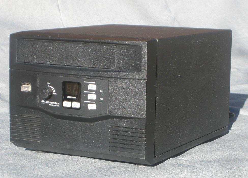
The GR1225 is a small self contained repeater (see photo below) that can be programmed to 16 different frequencies. The 3574 node repeater is also programmed to a second frequency of 444.500 - 449.500 MHz which is another frequency pair coordinated for this area. The built in duplexer handles this second frequency reasonably well with very little degradation, but this frequency is only there as a backup and adding it to the programming took less than a minute. The repeater operates from a built in switching power supply and there is a fan integrated into the housing for cooling. It often operates for hours at a time and there have had no temperature problems. The fan is temperature controlled and does not come on very often. The model in operation is a low power (1-10 watt) version. The author also has an older high power (25-45 watt) version as a spare, but has not yet tried it on IRLP. It is all programmed, but some of the connections on the Accessory Connector need to be reprogramed.
Below is a reproduced page from the GR1225 Service Manual explaining a bit about the available connections in the accessory connector on the rear of the radio. The fuctions of a number of the pins are programmable.
|
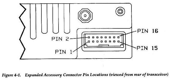
As mentioned above, a number of the accessory plug pins can be programmed for various functions. Several are electrically bidirectional but are programmed as either in or out. The manual says that Pin #8 defaults to COR, but on mine it was not, so that function had to be reprogrammed in addition to the operating frequencies, PL, timeout timer, and identifier parameters (callsign and 10 minute spacing) and to disable the internal repeat funtion. The repeater also came with an existing interconnect cable and all that was required was to move two of the pins in the accessory plug and put the connectors required to interface with the IRLP board on the other end. See the Expanded Accessory Chart below.
The table below is from section four of the June, 1997 version of the R1225 manual, part number 6880905Z53-O.
|
Section 4 General
|
The call sign identifier for IRLP can be programmed via software in the IRLP box, but this wasn't adequately researched prior to getting the radio programmed, so for node 3574 it is programmed into the radio itself. There is one inherent problem with using the built in radio identifier and that is if the repeater is keyed up before the identifier completes its cycle, it will start over again when the repeater is un-keyed. This is usually not a problem locally, but it is a problem when it is connected to a reflector and there is not a sufficient pause between transmissions for the identifier to drop out. Programming the call for higher speed helps in this case. There is also a programmable transmitter timeout timer which is currently set to 3 minutes and it gets timed out on occasion. A little longer time period might be preferable.
In my system the GR1225 Carrier Delay is set to Off. This means that if you "key up" you will not get a response back unless the identifier comes on. Our PL is set to 100 Hz. The use of PL on IRLP is HIGHLY recommended.
Just remember that if you need to make any changes to the configuration of the radio (i.e. the programming), it means another trip back to whomever has the RIB (the programming hardware) and the Radio Service Software (RSS / CPS), so try to get it right the first time. The author has a good relationship with the local Motorola dealer and was fortunate enough to wind up with a complete set of service manuals for the GR1225, but does not have the required software, progamming box or cable for programming the radio. If you end up with a GR1225 the two manuals that you will need are 6880905Z53 (the R1225 radio) and 6880904Z90 (the GR1225 cabinet, power supply, etc). The Radio Service Software has its own manual.
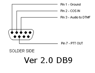
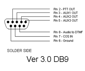
The figure below illustrates how the Version 3.0 IRLP Board is interconnected to the GR1225 repeater acccessory connector. Note that the IRLP board has its own DTMF decoder and the audio feed from the radio goes to both the computer LINE IN connection and also to the IRLP board pin 8.
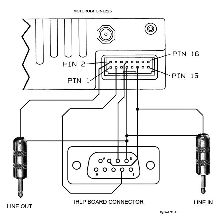
If you are using a Version 2 IRLP board you will need to use the two diagrams
below to identify the changes. Note that NOTHING in the pinouts is the same between
the two versions.
|
A final note, please do not request copies of the Service Manuals from the author. Many of the schematics are very large and with both books the stack is about 3/4 of an inch thick. Pretty much all of what you need to know is in the information above.
Don L. Blanchard - WA7GTU - Nov. 2006
Back to the top of the page
Up one level (Motorola index page)
Back to Home
This page originally posted on 21-Nov-2006
Photos and article text text © Copyright November 2006 by
Don L. Blanchard, WA7GTU
Artistic layout and hand-coded HTML © Copyright 2006 and date
of last update by Mike Morris WA6ILQ.
This web page, this web site, the information presented in and on its pages and in these modifications and conversions is © Copyrighted 1995 and (date of last update) by Kevin Custer W3KKC and multiple originating authors. All Rights Reserved, including that of paper and web publication elsewhere.