Back to Home
6-meter Repeater Transmitter
By Robert W. Meister WA1MIK

|
MaraTrac index Back to Home |
Converting a MaraTrac to a 6-meter Repeater Transmitter By Robert W. Meister WA1MIK |
|
I started this conversion with a stock MaraTrac mobile transceiver, model number T81XTA7TA7BK, which is a 110w 42-50 MHz radio with an advanced control head. It had previously been converted to receive in the 6-meter band. Since this radio was to be used only as a repeater transmitter, it just needed an audio input, a push-to-talk input, power, ground, and of course an RF Output. There was no need for a control head or any of the accessories.
Control Cable Connector and Interface:
I purchased a chopped-off 19-pin control cable connector from a popular auction site and completely stripped it clean. I rewired it according to the table below, using only the pins that were required. Input signals come from the control head and enter the radio chassis. Output signals leave the radio chassis and go to the control head. Refer to the explanation for each pin below this table.
| Pin | Signal Name or Use | Where It Goes To and Notes |
|---|---|---|
| 4 | Ignition Control Input | Tie to pin 19 (A+) |
| 8 | Data Input | 4.7k resistor to pin 10 (+5V) |
| 10 | +5V Output | Supply 5V to resistor to pin 10 |
| 12 | Push-To-Talk Input | PTT Input: Ground to Transmit |
| 13 | Power On Input | Power Input: Ground for On |
| 14 | Microphone High Input | Audio Input: Has +9VDC on it |
| 15 | Volume Control Wiper Input | Tie to pin 17 (Ground) |
| 16 | Xmit Light Output | To TX LED |
| 17 | A- (Large pin, large wire) | Main Power and Signal Ground |
| 19 | A+ (Large pin, large wire) | Main Power Input (+14VDC) |
Why did I use these particular pins? Here's a detailed explanation.
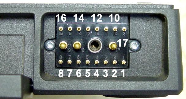
The image below shows the pin numbers on the radio's control head connector. They are also present on both sides of the mating cable connector. Some radios may have a thin piece of foam weather-strip material over the connector. Make sure you assemble the connector properly; all cables exit on the right (pin 17) edge of the housing.
I wired the heavy power lines first, then the remaining pins, using sleeving over the resistor leads and other short un-insulated jumper wires. I used a 3-foot length of Belden 8723 cable (two separate shielded pairs: black and red, green and white), wired per the color code in the table below. I ran the Audio Input signal in its own pair to reduce noise pickup; you can use a single shielded pair or individual wires if that's all you have. If the Audio Input line will be more than a few feet long, use a shielded cable for it. This radio may replace a Vertex VX-6000 mobile that has a DB-25F on the back for interfacing. The existing controller-to-radio cable (with a DB-25M) should plug right into this DB-25F connector. If this radio is to be used in place of a MaxTrac that's fed via the front panel MIC jack, you can omit the DB-25F connector and wires listed below and just drill a hole in the top cover of the MaraTrac and plug the modular cable directly into the modular jack that's used for programming.
| M-Trac | Wire | Signal Name | VX6000 |
|---|---|---|---|
| Conn. | Color | or Function | DB-25F |
| Pin 17 | Black | Audio Ground | Pin 18 |
| Pin 14 | Red | Audio Input | Pin 13 |
| Pin 13 | Green | Power On Input | - - - - - |
| Pin 12 | White | PTT Input | Pin 11 |
| Pin 17 | Shield | Ground | Pin 25 |
I assembled and tested (with an ohmmeter) the control head cable and connector first, as this allowed me to work on the radio and power it up without having a control head, microphone, speaker, and control cable clutter up the bench. I didn't wire up a TX LED but I might mount it in the side of the control connector housing. A miniature SPST power on/off toggle switch is temporarily dangling at the end of the cable; I might try to mount it in the side of the connector housing too.
If you don't have a spare control head connector, you can solder wires onto the back of the appropriate connector pins inside the radio, but then you'll need a way to get some wires out of the radio, by drilling a hole or cutting a slot in the top cover. Of course you can also use a clamshell or advanced control head and the appropriate control cable and attach wires to the mike jack pins, possibly through a used mike cable. I just didn't want to make too many physical modifications to the radio itself, and a control head connector was available.
Radio Programming and Configuration:
The radio was powered up by an Astron RS-35M power supply through the new control cable. The programming software had previously been hex-edited to allow 42-54 MHz frequencies. After connecting my computer, I read the original code plug, saved it to disk, and went through all of the Service Menu alignment and adjustment screens in RSS and recorded all of the tuning data. Even though I'll be fully initializing the radio, it's handy to have these values written down. I also noted the model and serial numbers, crystal and tuning numbers, and measured the 9.6V supply with a digital voltmeter, in preparation for logic board initialization.
I removed the existing firmware EPROM and installed one with amateur frequency ranges in it, so the transmitter would control its power and deviation properly over the 42-54 MHz range. I went through the full Logic Board Replacement procedure including selecting the model, frequency range, and serial number, and performed all of the alignment steps with the test equipment connected. The output power was set to 120 watts but I later reduced that to 100 watts. The maximum deviation was set to 5.0 kHz, which resulted in a PL deviation of 0.66 kHz. At some point the deviation may be raised to 7 kHz; the input audio signal level will limit the actual deviation. This will raise the PL deviation but a single resistor can be added to the logic board to reduce the PL deviation to 500-600 Hz. I will eventually add a pot for an external power control. Surprisingly, the radio transmitted fine over the full 42-54 MHz range, probably because the VCO coils had previously been adjusted to cover the 50-54 MHz part of the band. Since there's no loudspeaker or control head, I didn't check the receiver at all.
After alignment, I still had to program the radio. After the logic board was initialized, the software created two modes. I deleted mode 2 and programmed mode 1 with identical transmit and receive parameters of 53.1500 MHz and 67.0 Hz PL; this was also set as the "Home" mode. The timeout timer was set to 000 seconds. I left the radio capable of working with an Advanced (A7) control head. I thought of changing the control head type to "clamshell" but that really wasn't necessary. All other settings retained their default values.
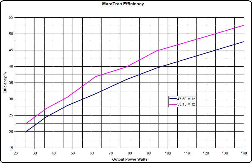
I decided to test the radio's efficiency over its full output power range by reprogramming the output power and measuring the RF output power and DC input power at 14.0 Volts. These measurements were obtained at the test frequency of 47.6000 MHz and the programmed frequency of 53.1500 MHz. The results are summarized in the table and graph below.
| RF | 48MHz | 48MHz | 48MHz | 53MHz | 53MHz | 53MHz |
|---|---|---|---|---|---|---|
| Watts | DC A | DC W | Eff% | DC A | DC W | Eff% |
| 25 | 9.0 | 126 | 20 | 8.0 | 112 | 22 |
| 36 | 10.5 | 147 | 25 | 9.5 | 133 | 27 |
| 47 | 12.0 | 168 | 28 | 11.0 | 154 | 31 |
| 62 | 14.0 | 196 | 32 | 12.0 | 168 | 37 |
| 78 | 15.5 | 217 | 36 | 14.0 | 196 | 40 |
| 94 | 17.0 | 238 | 40 | 15.0 | 210 | 45 |
| 115 | 19.0 | 266 | 43 | 17.0 | 238 | 48 |
| 140 | 21.0 | 294 | 48 | 19.0 | 266 | 53 |
At some point I may reprogram the radio with frequencies at 1 MHz intervals and connect a control head to the radio so I can test the transmit bandwidth over the full 42-54 MHz range.
Final Items:
Since the MaraTrac is a mobile radio, it is not rated for 100% transmit duty cycle, so one or more fans will need to be added to cool the PA heat sink and components. Some means of mounting the radio will also be performed to accommodate the fans.
The harmonic filter in the PA was designed to handle the 42-50 MHz band, so tweaking the coils and other components will be needed to improve the efficiency in the 50-54 MHz band. While the PA is out of the radio, the antenna relay will be replaced with a short length of coax going directly to a UHF female-to-female bulkhead adapter.
Adjustment pots may be added to the radio to allow manual control of output power, overall deviation, and PL/DPL deviation. Even though the firmware was replaced and the radio is fully aligned and functional over the entire 42-54 MHz band, a user may want to adjust the above parameters without having to drag a computer, RIB, and cables to the site. Also, the firmware may still try to reduce the output power if the radio gets too hot, or if the cpu thinks the radio has been transmitting so long that it must be getting hot, so a manual power control may still be needed to deal with that situation.
Test Equipment Utilized:
Contact Information:
The author can be contacted at: his-callsign [ at ] comcast [ dot ] net.
Back to the top of the page
Up one level (MaraTrac index)
Back to Home
This article was conceived February, 2019 and first posted 25-Mar-19.
Article text, photos, artistic layout, and hand-coded HTML © Copyright 2019 by Robert W. Meister WA1MIK.
This web page, this web site, the information presented in and on its pages and in these modifications and conversions is © Copyrighted 1995 and (date of last update) by Kevin Custer W3KKC and multiple originating authors. All Rights Reserved, including that of paper and web publication elsewhere.