Up one level (MTR2000 Index)
Up two levels (Main Moto Index)
Back to Home
|
|
Interfacing the
Motorola MTR2000 To
External Controllers
Originally Written And Published
By Robert E. Shepard
(Withdrawn At His Request)
Revised For Repeater-Builder
By Robert W. Meister WA1MIK
(Because It's Useful Information)
|
|

|
Preface:
I have to say this was one of the tougher controller interfaces I've had to deal
with, although it did not have to be. Determining which wire went where was not a
problem as much as dealing with a lot of quirks along with incomplete and occasionally
conflicting information from many sources. Hopefully, most issues will be covered here
lest the next person have a similar headache. This particular installation was to a
Computer Automation Technologies CAT-250 controller. However, the information should
be valid for almost any external accessory.
Start Prepared:
Before beginning modifications to any station, it is highly recommended that you
first test the station operation as is. Do not assume that the station, its features
or options, are working properly simply because they are physically present.
Required Items:
- RSS Software for the MTR2000: Unless you are very lucky, you can all but be
assured some level adjustments to the station are going to be required and this is
a "no screwdriver" device. Starting this operation without RSS handy may lead to a
lot of aggravation.
- 96-Pin (3 x 32) Male "Euro" Connector: This item is required to connect to the
system connector on the rear of the station, thereby allowing you to gain access
to the various I/O pins. It is available in a couple of varieties from DigiKey. I
used their part number A1265-ND, which had nice long 0.5" pins sticking out the
backside. More details on this connector will follow later.
- Proper Test Equipment: At the very minimum you will require a multimeter, which
can measure AC, preferably referenced to the dB scale. You will also want to measure
the RF outputs of the station to verify proper operation. A service analyzer is
always ideal. However, lacking access to one, some alternate form of monitoring the
station will be required.
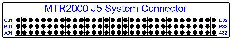
The Station Interface:
The physical connections to the station are straightforward, save for obtaining
the 96-pin connector, which for me was initially quite a hunt. The connector has 3
rows, A, B, and C, each with 32 pins. A word of caution here: the 3rd party male
connector will most likely have the pin numbers labeled on the connector body. Do
not go by these numbers! The back of the station's female connector is clearly
labeled and for reasons unknown, does not agree with the male connector's
manufactured labeling. The image below depicts the MTR2000 system (female) connector
as viewed from the rear of the station
Note: The matching male connector (cable connector) numbering-wise, is a
mirror of the female (station connector) when viewed from the rear (as it would be
connected) and identical when viewed from the pin side (pins facing you). It may be
that mirror effect of the pin numbering is because the male connector I used was
designed as PCB mount. In any event, when in doubt, use the pin orientation of the
station connector depicted here, which matches the station labeling.
The image below depicts the recommended pins for basic repeater operations along
with some additional accessory power and grounds. Again, the view is facing J5
(system connector) from the rear of the station.
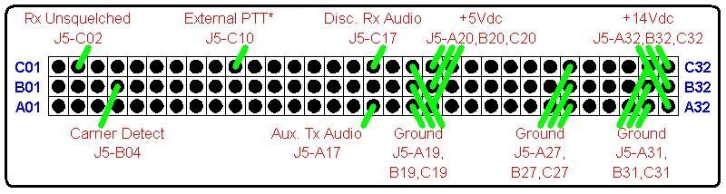
J5 System Connector, Pin Descriptions:
The following describes the connections to the station and their functions.
C02 - RX unsquelched - TTL output, Active High. Active when the receiver
audio is active (unsquelched). If the station is programmed for CTCSS or DCS (i.e.
PL or DPL), this line only activates when a signal with the proper code is received.
B04 - Carrier Detect - TTL output, Active High. Just as it says, active
when a carrier is present, regardless of the state of the receiver's squelch setting
or presence of CTCSS or DCS.
C10 - PTT - TTL input, Active Low [1]. Applying a ground to this pin will
activate the station's transmitter.
C17 - Discriminator Audio Output. Use coupling capacitor.
A17 - Auxiliary Transmit Audio Input [2]. Use coupling capacitor.
A20, B20, C20 - +5Vdc [3].
A32, B32, C32 - +14.2Vdc [4].
A19, B19, C19, A27, B27, C27, A31, B31, C31 - Station Ground [5].
The following additional I/O pins may be useful depending on your particular
operation.
A10 - VSWR_Fail, Active Low. Pulled up transistor output (10K to +5Vdc).
A04 - AC Fail, TTL output, Active Low.
Pin Notes:
[1]: PTT must be mapped in RSS to "Wire line and Auxiliary Audio" for external
controllers. Otherwise the audio path will not be enabled from the auxiliary transmit
audio input and no transmit audio will be heard.
[2]: The Auxiliary Transmit Audio level must be set in the RSS. This may or may
not be set depending on previous programming. By default, the value is zero (off),
and no transmit audio will be heard until this is corrected. This level is fixed on
stations with old firmware. You can find this in the Service menu.
[3]: Total 5Vdc current through all pins (summed) not to exceed 500mA
[4]: Total 14.2Vdc current through all pins (summed) not to exceed 1.0A
[5]: Total ground current through all pins (summed) not to exceed 1.5A
Cable/Pin Connector Tricks:
If you're like me, trying to solder wire onto a densely packed, multi-row connector
is a living hell. I came up with a little trick that works perfectly on this 96-pin
connector. On the ends of the wires, I attached a female pin for a DB-25 type connector.
This allowed me to slide the cable (pin actually) onto the 0.5" long PCB mount pins of
the male connector. Once in place, I simply soldered the female pin to the connector
pin, after which I slid on some heat shrink tubing to isolate and strengthen the
connection.
I recommend the removal of any unused pins from the male connector. The density is
such that a simple bump or cable tug could bend a pin (or pins) into a shorted situation,
resulting in the "smoke theory", which on the MTR2000 would be an expensive boo-boo.
I was initially going to put heat shrink over all unused pins but that was tedious,
not to mention the pins can be removed with a good pair of needle nose. The one drawback
is that with fewer pins, the connector does not remain as snug as it does when fully
populated. Use your best judgment or secure the connector with screws. Personally, I'd
rather chance having it fall out than have any shorted pins on the MTR2000.
Operational Quirks:
Having a talking controller, one usually would like to hear the repeater when it
actually is talking. What little information I had discovered on interfacing to the
MTR2000 was usually in reference to multi-tone, community repeater type operations.
As such, all of those articles recommended setting the MTR2000 to use carrier squelch
for TX and RX.
As a big proponent of using some form of CTCSS, I wanted full time encode/decode
operations. Since the CAT-250 controller does not provide CTCSS encode or decode and
the MTR2000 does, I figured why buy yet another device. I programmed the MTR2000 to
use its own internal encoder/decoder. This created an operational quirk that I
personally find to my liking, but others may be annoyed with. As such I am still
looking into a work around for those people.
The quirk is that the station will only transmit CTCSS/DCS while it is actively
receiving it. This produces the situation for a user running CTCSS/DCS on their
receiver, who will only hear actual repeated transmissions of other users. System
messages and the CWID are still being transmitted, but without CTCSS/DCS, so users
can only hear them if listening in carrier squelch. I am 100% positive this issue
lies with the MTR2000 itself, and perhaps there is a programming work around.
Alternatively, I may also have, in the case of the CAT-250, a way of not only
enabling the system messages with TX CTCSS/DCS, but also the ability to turn it on
and off via remote command. To be sure, the system messages and the CWID are always
transmitted; the question is simply whether or not CTCSS is sent with them.
Summary:
I've interfaced controllers to many different commercial and amateur stations.
Unlike the older vintage commercial gear such as the Motorola MICOR and GE's MASTR
series, these newer radios are not quite as easy to modify. However, with a little
bit of patience and reading, it is possible to emulate in software, what use to be
done with the soldering iron.
The information used in this document was put together from many sources, most
of all my own experience in configuring this setup. It is my hope that this document
will help to get your operation up and running a lot quicker than was my initial
experience.
Enjoy!
Acknowledgements and Credits:
This document originally Copyright © 2004 by Robert Shepard (June 11, 2004).
Motorola, MTR2000, PL, DPL, RSS, and a bunch of other terms are trademarks of
Motorola, Inc.
Contact Information:
The person responsible for re-publishing this article can be contacted at:
his-callsign [ at ] comcast [ dot ] net.
Back to the top of the page
Up one level (MTR2000 Index)
Up two levels (Main Moto Index)
Back to Home
This article originally written 11-Jun-2004.
Converted to HTML, revised and reposted on 27-Aug-2011.
Original article text © Copyright 2004 by Robert E. Shepard.
Article diagrams and hand-coded HTML © Copyright 2011 by Robert W. Meister WA1MIK.
This web page, this web site, the information presented in and on its pages and
in these modifications and conversions is © Copyrighted 1995 and (date of
last update) by Kevin Custer W3KKC and multiple originating authors. All Rights
Reserved, including that of paper and web publication elsewhere.