Back to Home
Station Index Page
Originally Compiled and HTML'd by Mike Morris WA6ILQ
Formerly Maintained by Robert Meister WA1MIK (SK)
Currently Maintained by Mike Morris WA6ILQ
|
Back to the Motorola index Back to Home |
The Motorola MTR2000 / MTR3000 Station Index Page Originally Compiled and HTML'd by Mike Morris WA6ILQ Formerly Maintained by Robert Meister WA1MIK (SK) Currently Maintained by Mike Morris WA6ILQ |
This index page has all of the information we have on the MTR2000 and MTR3000.
CONTRIBUTIONS TO THIS PAGE ARE WELCOME!
Actually to any page at this web site! Even one that just points out a typo.
|
One of the things we are looking for is the schematics of the high power and low power MTR2000 or MTR3000
power supply modules and RF amplifier (PA) modules. Does anyone have a PDF, or even a paper copy that we can scan? Or a pointer to someone who can repair the power supplies or the PAs? Another item that we are looking for is the schematic of the Motorola CDN6351A cable which was originally designed by Zetron as the 950‑9919. It was used to connect a variety of external equipment to a paging or repeating station (example: MTR2000 or MSF5000). That cable has an integrated summing amplifier that mixes two audio sources like a tone (paging or PL) encoder and transmit audio into a single output to the transmitter. If anyone has one sitting on a shelf we'd like a photo or two and to borrow the included paperwork for scanning. |
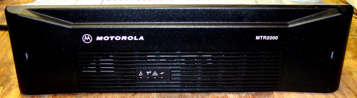
The MTR2000 is a rack-mount repeater designed by Motorola of Israel that was available in VHF, UHF and 900 MHz ranges and in two different power levels (1-40 watts and 25-100 watts). New price for a MTR2000 UHF 100 Watt in 2002 was in the US$7000 range. The "Intent to cancel" notice was dated 11/01/2009 and orders were accepted until 3/31/2010. MTR2000 support was available until 4/30/2017. The MTR2000 was replaced by the MTR3000 (which was DMR oriented and available as VHF and both a 403‑470 MHz unit and as a 470‑524 MHz units). The MTR3000 has also been discontinued and was replaced by the SLR product line.
You used to be able to purchase (for a lot of money) a conversion kit to convert
your MTR2000 station to an MTR3000 station. The kit contained a replacement
exciter, a replacement receiver, and a replacement control module, as well as a
new front cover. If anyone has done this please contact the author… we'd like
some info… especially if you kept the conversion instructions (we'd like to
scan them if they are't already in PDF form).
Basically you threw away the control module, exciter and receiver modules, keeping
only the power supply and the RF power amplifier.
Your author was told that because the MTR product line was designed by Motorola of Israel that a lot of the MTR manuals were never orderable through the parts system like many of the other Motorola product lines. The author has not been able to determine if that decision was made by Motorola of Israel or Motorola USA. And Motorola is reticent to provide information on the units. As such schematics and service manuals for the MTR stations are very difficult to acquire…
Example: A number of vendors built power supplies for Motorola; some of the MTRs that the author has worked on have supplies made by Astec, and when your author contacted them they said that they are not allowed to release any information. Another power supply manufacturer was Ascom Energy Systems, a third was ABB, a fourth was Emerson, and there were others. Every manufacturer that I contacted said that they would / could not supply any information.
Motorola expected you to simply field swap the FRUs (Field Replaceable Units), and they are NOT cheap… In 2012 the 100 watt station power supply module was over $500 plus shipping - and with an 8 to 10 week delivery. In 2021 the same power supply was about $1100. The 100 watt UHF PA deck was priced even higher.
Repeater-Builder has had a few manual PDFs appear (still no power
supply schematics), if anybody has any additional manuals or other info that
they would like to donate to this page please let us know. If they are paper
we can scan and return them! If you would like to be anonymous that's
fine – just look up WA6ILQ on QRZ.com and use that
snail-mail address to ship a CD or DVD. If you are going to ship a paper
manual please email him first.
If anyone has access to the Depot Manuals (VHF, UHF or 900 MHz
for the MTR2000 or MTR3000) or anything that might be useful in repairing
the power supplies or PA assemblies please let the page maintainer know!
If they are on paper we'd like to borrow them, scan them and return them.
If they are PDF's and you want to remain anonymous then put them on
a CD or DVD or just stick them on a thumb drive and snail-mail it to
the page maintainers QRZ address.
The MTR2000 Models and Frequencies
The MTR2000 model numbers are T5544 and T5766 but those numbers don't indicate band, RF power or anything useful. One number was used when the station was ordered through a dealer, and the other number was used when the station was ordered directly from Motorola inside sales.
| Input Mains Voltage AC: | 85‑264 Volts AC, 47‑63 Hz (there is no 120 / 240 volt switch or a mains on / off power switch) | |||
| Optional DC Only Operation: | 14 VDC (30 or 40 watt Station) 28 VDC (25‑100 watt VHF or UHF station, 20‑75 watt 800 or 900 MHz station) |
|||
| Size and weight: | 19-inch Rack Mounting, 3 Rack Units high (5 1/4 inches tall), 40 pounds / 19 kg | |||
| Temperature Range: | -30°C to +60°C (-22°F to +140°F) | |||
| Antenna Connectors: | Transmit and Receive are both type "N" female | |||
| Channel Spacing: | VHF: 12.5, 25 or 30 kHz | UHF: 12.5 or 25 kHz | ||
| VHF | RX: 132-174 MHz | 2-30 watt or 2-40 watt TX: 132-174 MHz | 25-100 watt TX 132-154 MHz * or 150-174 MHz * | |
| 350 MHz | RX: 335-405 MHz | 2-40 watt TX: 335-405 MHz | (there was no high power option for 335-405 MHz) | |
| UHF-1 | RX: 403-433 MHz | 2-30w or 2-40w TX: 403-435 MHz | (there was no high power option for 403-435 MHz) | |
| UHF-2 | RX: 433-470 MHz | 2-30w or 2-40w TX: 435-470 MHz | 25-100 watt TX 435-470 MHz (do not run below 25 watts) | |
| 800 MHz: | RX 806-825 MHz | 20-75w TX: 851-870 MHz (there was no low power option in 800 MHz) | ||
| 900 MHz | RX: 896-901 MHz | 20-75w TX: 935-941 MHz ** (there was no low power option in 900 MHz) | ||
The MTR comes in two RF power levels for VHF and UHF: 1‑40 watts and 25‑100 watts and all of the PA decks are designed for continuous duty. The difference between the low power and high power transmitters is the power supply module and the RF power amplifier module. There was an Field Service Bulletin (FSB) that advised not running the high power units below 25 watts. Anybody have a copy that we can scan?
The low power power stations use the "250 watt supply" and it outputs 14 volts DC and 5 volts DC. A number of people prefer the low power power stations as they can be powered from 14 volts DC therefore from a site backup battery bank. The DC input on these low power stations will require a 12 or 14 volt battery and an external charger. These stations can have either a 30 watt or a 40 watt transmitter and can be set to any power level from 1 watt to the full power and can drive an external continuous duty power amplifier to whatever power level you can afford (common external RF amplifier input levels are 2, 5, 10, 25 and 30 watts).
The high power stations use the "500 watt supply" and it has the same 14 volts DC and 5 volts DC plus is has 28 volts DC which used only for the high power PA deck. The DC input on these high power stations will require a 28 volt battery and an external charger.
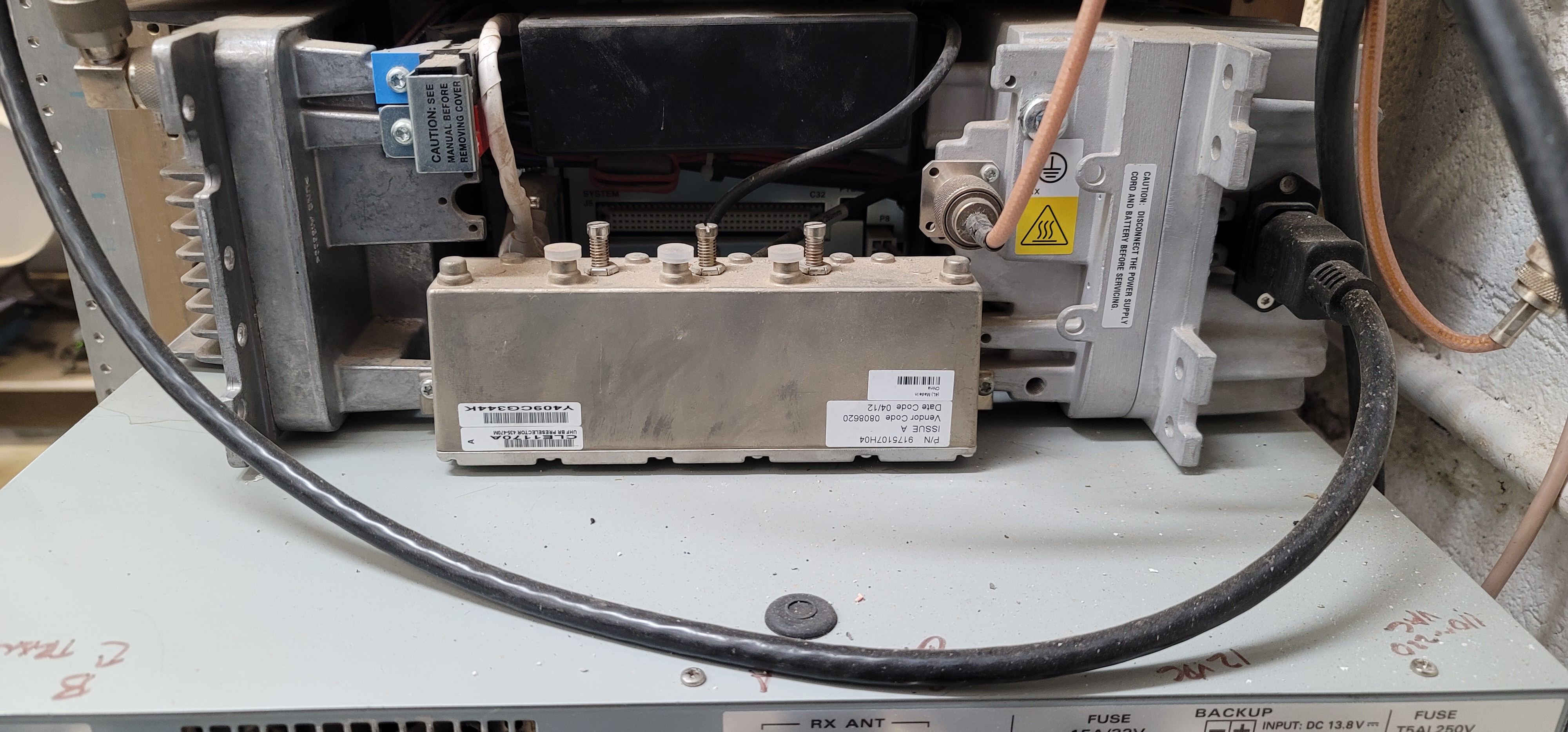
The exciter module is connected to the RF power amplifier module via a multiconductor cable. The power amplifier tells the exciter module what frequency and power range it is by way of various DC voltages - and that voltage is generated by a resistive divider inside the PA and carried to the exciter by one lead in the cable between the amplifier and the exciter. There is an article below that tells you how to modify the VHF high power / high range (150‑174 MHz) VHF power amplifier voltage divider so that it lies and tell the exciter that it's a high power / low range (132‑154 MHz) amplifier. This resistive fakery allows the transmitter to operate below 150 MHz. Just remember that modifying the resistive voltage divider inside the 150‑174 MHz power amplifier to lie that it is a low range unit does not change the RF amplifier characteristics – the unit is still a high range amplifier. It will work down into the 145.100-145.500 MHz repeater outputs but not much below that.
Out Of Band Operation:
The MTR2000 RSS / CPS can be hex edited to allow out of band frequencies to be entered and loaded into the control board HOWEVER the firmware in the receiver and exciter modules will decide if the frequencies are acceptable (i.e. in-band) or not. This is the voice of experience. There is an article below on how to extend the low range UHF1 station upwards, that works only because the exciter and receiver frequencies are still within the range allowed by the firmware inside the receiver and exciter modules.
One contributor to this page wanted to stretch a 403‑470 MHz range 100 watt MTR2000 to talk at 471 MHz and receive at 474 MHz range (470 to 476 MHz is TV channel 14 in the USA however in some areas it is a commercial repeater band with a +3 MHz offset). He was able to hex edit the RSS to allow the codeplug to go up to 476.000 MHz, but the receiver and exciter modules had their own frequency limits (set by their own firmware internal to the module) and refused to accept the 471 MHz transmit / 474 MHz receive frequencies programmed into the codeplug.
Later on the contributor found out that there is a voltage divider inside the individual receiver and exciter modules that tells their microprocessor what frequency range they were built for, and the internal firmware "knows" about 470-476 MHz), but there never were exciter, receiver or PA modules manufactured for 470-476 MHz. However by that time he had already located and was using different equipment for his 471 / 474 MHz requirements (both the Icom FR‑6000 and FR‑6300 repeaters were used and programmed for 5 watts output, followed by 470‑476 MHz Henry Electronics continuous duty 100 watt amplifiers).
Crossband Operation:
The MTR2000 hardware is certainly capable of crossband operation, and the engineers might have included it in the firmware and programming software. Your author has not had the opportunity to experiment with it and has been told that it was not one of the design requirements (which may or may not be true). If anybody has actually swapped receivers to create a crossband station (i.e. VHF receiver into a UHF station, or vice versa) please email the author with your results and he will update this paragraph.
Using an External 5 or 10 MHz Reference:
Some sites have a high stability master oscillator (usually a 5 MHz or 10 MHz GPS Disciplined Oscillator (GPSDO) followed by a splitter / distribution amplifier). If yours does (and the landlord
will allow you to take a feed from it) then you can run a cable from an extra
output on the distribution amplifier to the external reference BNC jack on the MTR (labeled J5603).
The reference input is high impedance, and is looking for a signal between 1 volt and 3 volts p-p.
Note that the MTR does not have an automatic fall-back on the external
5 / 10 MHz reference. If you have configured the MTR to use an
external 5 / 10 MHz reference and the external reference signal dies
for any reason the MTR system module will generate a fatal alarm and the MTR will
not receive or transmit.
The MTR3000:
Your page maintainer was told by multiple people that the only hardware
difference between a MTR2000 and a MTR3000 are the system
controller, exciter and receiver modules and the plastic front panel.
Photo 1-MTR3000 with front cover
Photo 2-MTR3000 less front cover (Photos found on the web. Both open in a new browser tab)
The MTR3000 was a update to the MTR2000 and the changes supported
DMR / MotoTurbo but sacrificed the paging (and flat audio)
capabilities. As such the MTR3000 appears to be nowhere near as flexible
as the MTR2000, and the MTR3000 looks like it is really only useful as a
high power conventional repeater or as a DMR / TRBO station
(but at 100 watts continuous duty – four times the power of a
MotoTrbo XPR8300 station). The interfacing of a MTR3000 to an external
controller is also very different. A lot of the MTR2000 info applies.
Your author has no hands-on experience with the MTR3000 other than
occasionally helping a friend that inherited the maintenance duties on one.
For interfacing and programming details look at the Stephen
Gansky W3AAD article below: "Configuring an MTR3000
for Analog Allstar Operation".
The MTR3000 cannot use the MTR2000 programming software, it uses MOTOTRBO software. The last version of the early CPS software was Version 16 build 828. The next version was released as CPS2.0. There were MAJOR differences and many owners have chosen to stick with 16.
If your MTR3000 is locked into narrowband then you have two options to enable wideband:
I just happened to run across another solution for the MTR3000 to enable the wideband operation without going thru getting the entitlement from Motorola. It is a hexedit modification to a file in the CPS Version 16 build 828 programming software. After installing the CPS, you find a file sfccomb.dll, and do a hexedit on that file at location 0000200E, changing the byte from 06 to 17, and saving back, replacing the original file. I used "hexed.it", an online hex editor to make the change. After the patch is installed the CPS will now allow you to set the MTR3000 to 25 kc wideband operation! 73 and have a great day!
If anyone would like to contribute some additional MTR2000 or MTR3000 information please let the page maintainer know.
The Four LEDs: The following information may or may not be useful on the MTR3000.
The MTR2000 has four LEDs on the front of the unit. The leftmost is the Status LED, and is the most useful. The information that it can display is:
| Off: | No AC or DC Power Present |
| Green On: | Passed All Power-Up Diagnostics, Station Operating Normally |
| Green Flashing: | Station is in Service Mode |
| Red Flashing: | Station Operational but Not Fully Functional - Minor Failure |
| Red On: | Station Not Operational – Major Failure |
| Green/Red Flashing: | Station in Bootloader Mode (you will probably never see this) |
One of the most common causes of a blinking red status LED is where the hardware configuration does not match the codeplug; one possibility is when the station codeplug has a wireline audio card programmed and the board is missing... the control module is still looking for it during boot-up. The MTR2000 firmware "knows" about the TTN5066, TTN5067 and TTN5068 modules, all of which can be configured for either 2-wire or 4-wire operation. The only AUX I/O module that is in the RSS menu is the CLN6698… they were an option and as such are not common and when found may not be inexpensive.
Another cause of a blinking red status LED is when the AC power supply has failed and the unit is being powered through the DC jack on the back (this situation also puts an annoying periodic beep on the speaker audio if you don't tell the MTR that it's supposed to be on DC on one of the CPS screens).
Yet another cause of a blinking red status LED is a bad TRC board, a bad receiver, exciter or a bad option board could also cause the control module to throw an error. And it may not be a module problem, as your author has seen dirty connectors in the card cage slots and bad connections from the control module to the exciter or receiver modules.
The second-from-left LED is the green LED and is the "RX" LED. It is green when the receiver is active.
The second-from-right LED is the yellow led and is the "FailSoft" LED. It is only used in trunked radio systems and the conventional user will never see it lit.
The rightmost LED is the "PA Key" and can be:
Green On: Transmit Mode, PA Keyed
Green Flashing: PA Keyed, Transmit Power reduced due to Fault
CPS, Programming and Configuration:
The MTR2000 can be programmed to operate as:
Your author has several MTR2000s in commercial service and helps on a few amateur systems that use them; all are configured as a full duplex base station with an external controller.
The MTR2000 programming software, RSS part number RVN4148, was originally provided as a package containing dual media – it contained two 3.5 inch diskettes and also a CD. The RVN4148 RSS will run under Windows 3.1, 95, 98, XP, and it is known to work on 32‑bit Windows 7, Windows 8 and Windows 10.
This RSS is old enough that it only "knows" about COM1 through COM4. Another limitation is that the "codeplug" files that are saved and loaded are limited to the MS-DOS filenaming format (8 character filename prefix, then a dot / period, then a 3 character filename suffix).The version to look for is RVN4148P version R03.03.02 as that is the final version and both it and three of the prior revisions (R03.02.01, R3.02.04 and R03.03.01) are "out there" on the internet. The MTR2000 will do both wide and narrow deviation and does not need an entitlement key to run wideband.
No long filenames!
The MTR has an internal RSS-managed digital softpot on the external
transmit audio input. That input can be programmed for pre-emphasized
or flat. When you factory default an MTR2000, the digital pot is set to
zero. The previous owner of a new-to-you MTR may never have used the
external audio input (used the internal repeat function) so that softpot may
still be defaulted at zero. If you do not know the history on a new-to-you
MTR you could find that pot set to zero. As a result a first attempt
at interfacing an external repeater controller may result in zero
transmit audio.
The only way to resolve this is to use the RSS to adjust the Aux Audio
level softpot to a reasonable value (personally, I start at 80% and
adjust from there).
The RVN4148 RSS / CPS will NOT run under any 64-bit Windows. If anyone knows a way to enable 64-bit Windows to run XP vintage software please let the page maintainer know! You will make a LOT of people very happy after he posts that info here and on several other pages at this web site.
We were given a PDF of the RVN4148 RSS Manual version D. (68P81096E15-D) (65 pages, dated 06/28/2005)
If anyone has a later edition we'd appreciate an emailed PDF.
The RVN4148 RSS works with either a real hardware serial port (COM port) on a
computer that has one or with a good FTDI based USB to serial adapter. The author uses
a Toughbook CF-30 laptop that has a real COM port and
a custom-wired DE-9 to RJ-45
adapter made from an old ethernet cord.
Friends use this FTDI USB programming cable from BlueMax49ers (Mark Dunkle KJ6ZWL). (off-site
pointer, opens in a new browser tab) No, he's not paying for that pointer, his FTDI cables
just plain work, and do so with the stock Windows drivers.
There are some notes on USB to serial adapters and USB programming cables on
the RSS & RIB page at this web site.
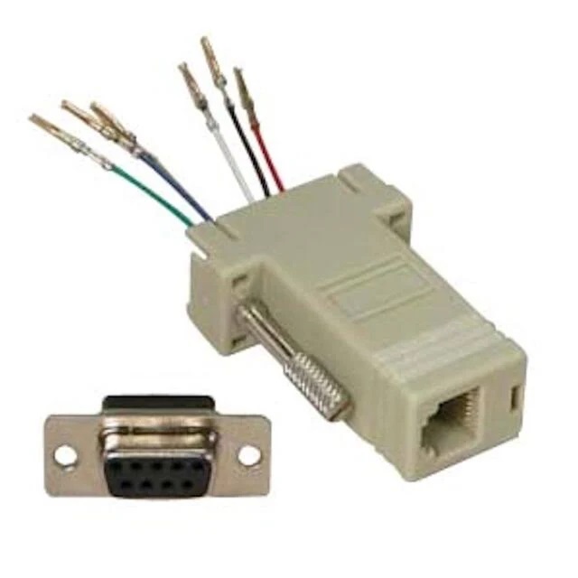
The factory MTR2000 programming cable (Moto part number 30-82056X02) is NOT your normal RJ-45 programming cable. The MTR2000 programming connection uses regular RS-232 voltages and does not need a RIB. You can make your own 9-pin serial programming cable in two different ways: first from a common ethernet cable connected to a female DE-9 to RJ-45 adapter and second from a female DE-9-pin connector and a stub of an Ethernet cable. See these two photos: Photo 1 and Photo 2.
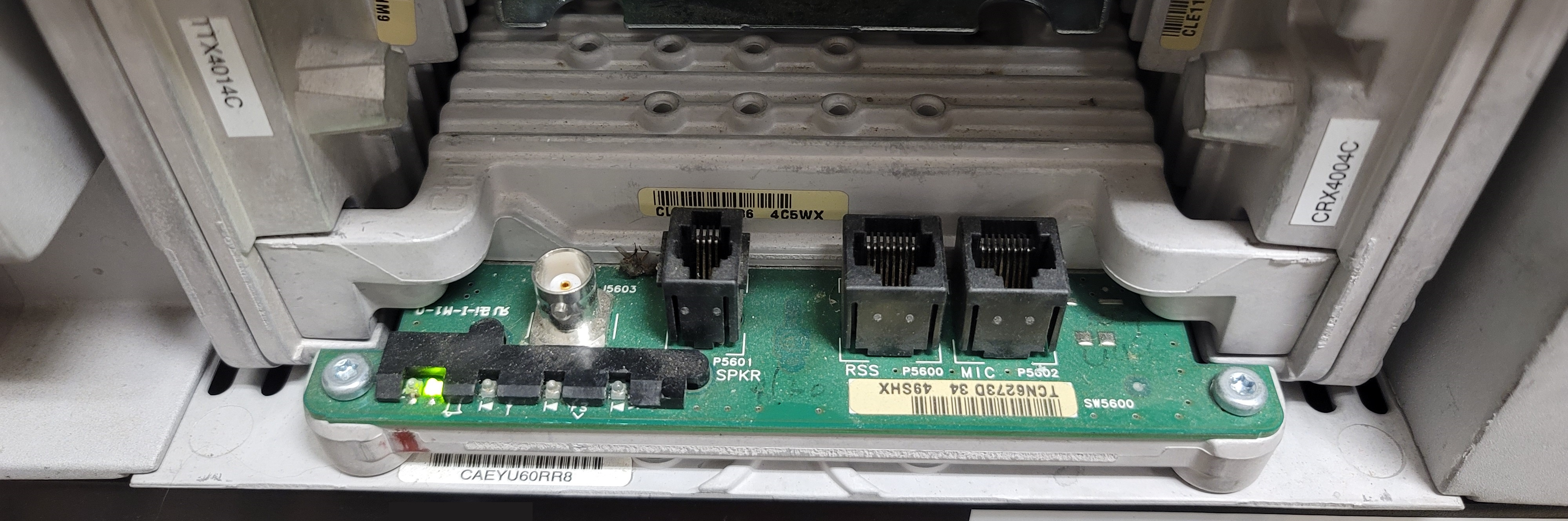
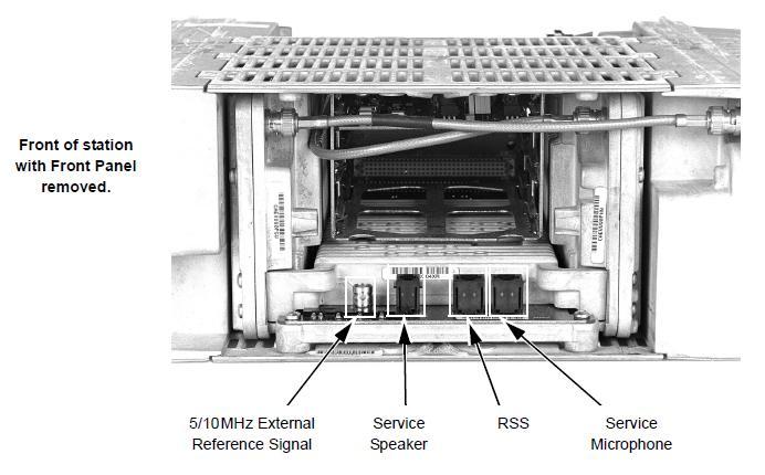
The MTR2000 programming connector is behind the snap-off front cover on the front of the control module. Look for a horizontal circuit board protruding out the bottom front Photo with four LEDs, a female BNC connector (for an optional external 5 or 10 MHz reference), a 4-pin RJ-9, RJ-10 or RJ-22 labeled SPKR P5601 and two RJ-45 connectors, one is labeled "RSS P5600", the other is for a special test microphone and is labeled "MIC P5602".
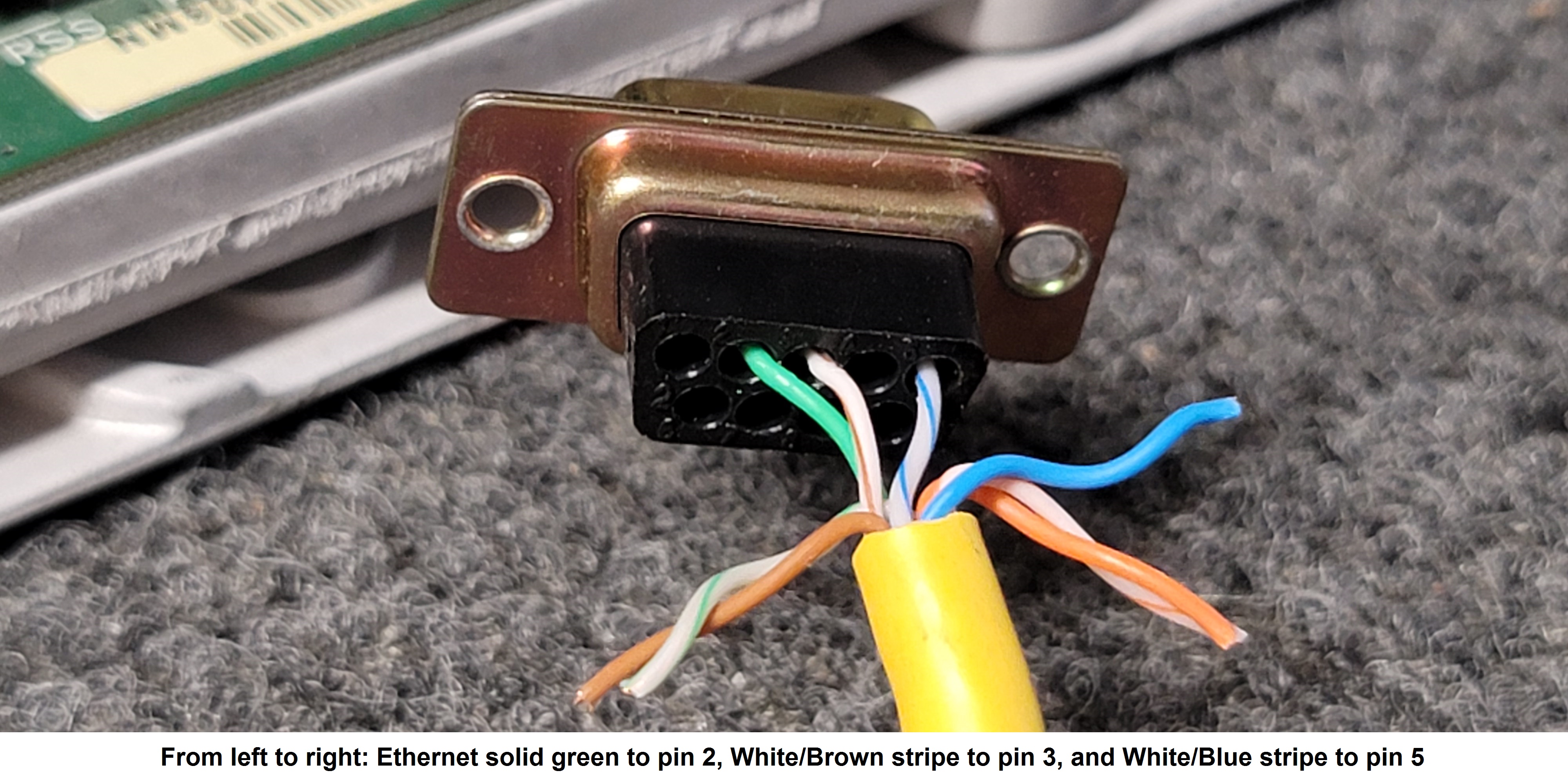
The only RS-232 signals that are actually used by the MTR are pins 2, 3, and 5 of
the computers DE-9 serial port. They feed pins 3, 2 and 4 of the MTR2000 RSS jack,
and depending on which web site (not this one) you believe and which manual you
believe pin 1 might be on the left side or the right side of the jack!
The RJ-45 RSS jack has pin 1
nearest the MIC jack, not the BNC jack.
The actual serial programming cable is a simple 3-wire crossover cable:
Computer                       MTR2000 RJ-45 (labeled "RSS P5600")
9 pin                          (Note that pin 1 is the rightmost pin and that the three
female                         active pins are on the right side of the RJ-45 plug/socket)
  3 -------------------------- 2
  2 -------------------------- 3
  5 -------------------------- 4
If you are going to use a 9-pin COM port the simplest way (and the one that minimizes cable proliferation in the field programming computer bag) is the custom-wired female DE-9 to RJ-45 adapter and a normal ethernet cable.
There is an article below by Robert Meister WA1MIK that describes how he made a
single cable that programs both the MTRs and the normal RJ-45 microphone jack mobiles…
Maxtracs, Radius, GM300s, GR1225s, MTR2000s, MSF5000s, CDMs, XPRs, etc.
I strongly recommend that one of the first things you do when
you acquire a new-to-you MTR2000 is download the existing programming and
tuning data and save the files so that if something gets screwed up you have a
known good backup and can backsetp to your original configuration.
It's better to have a backup that you don't need than one you really need and will
never be able to get.
Note that the MTR RSS is so old that it only allows an 8-characters-dot-3-characters file name. So download the file as MTR2K.ORG (or similar), then copy it and change the name of the copy to something like mtr2000-codeplug(dot)original. Maybe add "-(serial number)" or "-(year)-(month)-(day)" in there if you want.
As mentioned above your author has a laptop that is dedicated to radio programming.
He uses a Panasonic Toughbook CF‑30 because it is pretty indestructible, has a hardware COM1 on the back (that always works!), and was cheap (complete and fully operational for under $300 complete with a new 1 TB hard drive (later an SSD)
and maxed out to 4 GB of RAM). It is running 32 bit Windows 7 (with Service Pack 1) and does everything that he needs and do it on multiple
brands of radios, repeaters and repeater controllers.
He also has a CF‑31 Toughbook that runs 64-bit Windows 10 for the radio
software that is 64-bit only (like "Chirp" or the Motorola APX line). Both
Toughbooks can take a fall from 6 feet onto concrete and shrug it off (there have
been multiple unintentional drop tests over the last decade).
There is a lot more info on dedicated radio programming computers in the article
here.
There have been instances of MTR2000 codeplug deterioration or corruption, and one person reported that it seems to show up most often when the same codeplug is repeatedly downloaded, modified, and uploaded. That person treats his MTR as a "write-only" device and makes the chages to a stored codeplug and uploads it.
Always save (as a backup) the codeplug that you first download from a new-to-you MTR2000 station, even if it has commercial frequencies. Likewise download the tuning data. Stations with corrupted codeplugs have been recovered by generating new codeplugs, but having a "clean" original archived codeplug from your station (even if it has commercial frequencies in it but with your exact hardware configuration and tuning information) is, to use a Martha Stewart term, A Good Thing.
Note that using an external controller requires you to set the MTR to full duplex in the station configuration AND if you have the wireline card installed there are settings in the wireline configuration for 2-wire mode versus 4-wire mode. Full duplex operation requires the wireline card to be set to 4-wire mode even if you are not using it. One of the most common initial setup mistakes is to have the MTR station set to full duplex and the wireline card set to half duplex (2-wire mode).
The factory default carrier squelch setting in the RSS is a value of 100, which I feel is too high. Setting it any lower than about 35 to 40 causes the receiver to unsquelch. I find that a value of 45 to 50 is usually what works the best (resulting in a threshold of about 0.25µy (-119 dBm). Your local noise floor may require some adjustment. Once the carrier squelch is set properly then I enable the PL / DPL decode (the local radio environment here in Los Angeles requires PL or DPL decode on everything).
If you are using the wireline card for audio input and output then you need to map the external PTT (EPTT) to the wireline audio input in the RSS.
The CPS has a field on the frequency set tab labeled "Idle Frequency". The MTR runs the lowest level exciter stages 24x7 so there is always a bit of carrier leakage. In a simplex base station configuration it's mandatory that the Idle Frequency field be different than the transmit frequency. In a repeat environment I always set it about 250-300 KHz away from the repeater transmit frequency just so that my handheld isn't unsquelched the entire time I am on-site.
Summary: You will need a computer running 32‑bit Windows XP, 7 or 10 to program an MTR2000. And the simple solution to the programming cable is to use an ethernet cable and build a 3-wire DE-9 to ethernet plug adapter or to buy this FTDI USB one from BlueMax49ers (Mark Dunkle KJ6ZWL). (off-site pointer, opens in a new browser tab)
The MTR2000 ID'er
When the MTR2000 is programmed as a stand-alone repeater (i.e. for in-cabinet repeat) the internal MCW ID is a "polite" ID – it will be transmitted when the station is otherwise idle, which is standard for Motorola equipment. If the station is keyed up during the MCW ID, it will stop transmitting the ID and try to do it all over again when the station again goes idle. It could go on like this forever and may never completely ID…
There is a checkbox option to transmit the ID without PL or DPL.
The only identifier parameters you can change in the MTR2000 RSS are the MCW ID character string and the ID interval; any other settings (such as tone frequency) aren't an option in the RSS.
To stay legal in the amateur radio service many have disabled the MTR internal IDer (just delete the ID text) and used the IDer in an external repeater controller (with the MTR programmed in BASE mode).
MTR2000 Fans
The MTR power-up self-test switches on the fans in both the transmitter power
amplifier and power supply for approximately 10-15 seconds when power is first
applied as a diagnostic indicator that the fan is functional. They also turn on as needed
during normal operation. If either fan should fail, an alarm tone will be sent over the
air if enabled. I suggest that you enable that!
The thermistor that controls the PA fan is mounted inside the RF Power Amplifier,
it is 100 K±10% and 240mW. It drives two separate IC Gates
U4505 and U4508 controlling the Temperature Sensing and Fan Enable circuitry
within RF Power Amplifier assembly.
As expensive as the PA deck and power supply modules are (and how working
replacements are becoming unavailable) I suggest that you swap the fans every
few years.
David Ranch KI6ZHD reported that the fans in the 100w station he worked on
were "Superred" brand part number CHB12012CB(E), two wire (no third wire
tachometer connection), 12vDC, 120mm square fans and 25mm thick.
A few random MTR2000 notes…
From the MTR2000 Product Planning and Ordering Guide R4-2-97B November, 1997:
Wide Receiver:
The standard configuration for UHF and VHF stations utilizes a receiver module that includes a wide (electronic varactor-tuned) preselector. This wide preselector is best suited for low density RF environments, when stations are used with external multicouplers, or when multifrequency operation beyond 4 MHz is required. This wide receiver uses a single receiver module to cover the entire band, 132-174 MHz or 403-470 MHz.
Narrow Receiver:
The optional configuration (X265) for UHF and VHF stations utilizes a receiver module and an externally mounted High Performance narrow preselector. This configuration provides better performance for customers intending to locate the MTR2000 with other stations in the same frequency band.
The optional High Performance narrow external VHF and UHF preselectors are tuned to cover a 4 MHz section within the operating bandwidth of the receiver module without any change in performance. On VHF Stations, two ranges of external preselectors cover the entire band: 132-154 MHz and 150-174 MHz. (If frequencies in the 150-154 MHz overlap region is specified, the lower band preselector may be selected with the X326 option, otherwise the 150-174 MHz preselector will be automatically selected.) On UHF Stations, two ranges of external preselectors cover the entire band: 403-433 MHz and 433-470 MHz.
MTR2000 or MTR3000 Speaker:
The audio output of the MTR does not have a true speaker amplifier stage. The speaker jack will drive a small earpiece but generally you will want an amplified speaker. The designers at Motorola chose to not reinvent the wheel when it came time to design the MTR speaker unit. They just used the existing amplified speaker and cable kit that was already used on several mobile handheld chargers. The speaker has a 6-pin Molex connector on it for audio in and 12 volt DC power in. The kit consisted of a HSN1000A (or B) or the HSN1006A (or B) external amplified speaker and a 0185180U01 speaker cable. (opens in a new browser tab) The MTR speaker and cable set was also used on the later Quantar / Quantro product lines. As I write this the "Motorola HSN1000 and the 0185180U01" cable can still be found for under US$30 dollars (or $60 for both).
Note that the 4-pin modular P5601 SPKR jack is NOT a common RJ-11 / RJ-12 / RJ-14 style connector. Instead it is an RJ-9 / RJ-10 / RJ-22 (they are all the same 4-pin connector body) and is most commonly found as the narrow modular connector used for wired telephone handsets (and you can find them and the crimping tool on Amazon).
Rather than buying a RJ-9 / RJ-10 / RJ-22 connector and a crimper the easiest way to find a mating cable is to recycle a old wired telephone handset cable (it has 4 conductors, the color code varied with the manufacturer). A Western Electric type 107 speaker or a common PC amplified speaker will work just fine, look for one that uses +12 to +14 volts (some do and you can tap the power pins on the P5601 SPKR jack for those speakers), others are powered by a 9 volt or 5 volt wall wart, some are powered from a USB jack (also 5 volts)... You can find +5 volts on pin 8 of J17, ground is adjacent on pin 7). You can determine the pinout of the SPKR connector with an ohmmeter, connect one lead to chassis ground, use the other to probe the pins on the SPKR jack (with the MTR or Quantar unplugged!)... The end pin that is grounded is pin 1, pin 2 is 14 volts DC to power the amplified speaker, pin 3 is the audio ground, pin 4 is the line audio output (max about 1.4-1.5 volts peak to peak or about 1 volt RMS).
MTR2000 or MTR3000 AC Mains Power Cord Caution:
The AC power cord that is used with the 100 watt MTR2000 or MTR3000 station is a heavy duty cord with an uncommon high-current "IEC320 C15" connector on the MTR end: Note the side notch - that feature was designed to prevent a common (low current) desktop-computer-grade 16 or 18 gauge IEC cord from being used. Get a real Type IEC320 C15 cord like this one. Here's a photo of the MTR connector and of the Power Cord Connector. Do NOT just cut a notch into the connector on an undersized cord like this guy did (looks like he used a bench grinder!) Yes, your author found that 18 gauge cord with a homebrew notch in use on a 100 watt MTR on amateur frequencies at a commercial site… This is the kind of stupidity that gets hams kicked out of commercial sites. (all of the links in this paragraph are off-site pointers, each opens in a new browser tab)
AC Mains Power Supplies:
The MTR2000 and MTR3000 power supplies are interchangeable and were made in
both low power and high power versions plus there was a 48 volt DC input version
(we have no info on that other than it existed… any info and a photo would be appreciated).
There is no 120 / 240 Volt selector switch on an MTR power supply, all
are 85-260 volts AC, 47-63Hz.
The last high power MTR3000 supply I saw was part number DLN6707A / DLN6622 (the low power one is a DLN6624). When I priced the high power one it was $1100.
There are two different "generations" of AC supplies: essentially the MTR2000 supply and the MTR3000 supply. There was a time period after the MTR3000 was released but while the MTR2000 was still being supported… during that time Motorola would provide MTR3000 supplies as warranty replacements for failed-in-warranty MTR2000 supplies.
How to tell if you have a MTR2000 supply or a MTR3000 supply:
Take the sheet metal cover off the outside of the power supply module. It's held
in place with 5 screws. There is a small circuit board inside. If the board
has parts visible then it's a MTR2000-vintage supply. If you see the back side
of a circuit board (no visible parts) then it's a MTR3000-vintage supply.
Your authors experience is that that the MTR supplies are physically solid but electrically fragile… They need a really good AC surge supressor on the input, at least something like a Eaton / Tripp-Lite Isobar a four outlet unit is shown on their web page, they also are available in six outlets. I have an eight outlet unit under my desk, they apparently aren't making those any more.
Another possibility is a constant voltage transformer (CVT), also known as a
ferroresonant transformer. This unit provides a stable (±1%) output
voltage despite ±20% fluctuations in the input (mains) voltage. It regulates
the voltage and also clips the voltage spikes using a saturated core on the transformer
and the resonant circuit (an auxiliary winding and a capacitor) and also helps to filter
power line noise. The smaller models are 120 volts, the larger ones can be
wired for 120 volts or 240 volts on both the input and the ouput. The
ones I have used idle at an amp or so and run a few degrees above room temperature
even when under no load. There are different models for 50 Hz and 60 Hz.
One manufacturer is
Sola Corporation,
and new prices are in the $700+ range (in 2019), they can be frequently found
in industrial surplus. About 1995 the author found a 120 volt 500 watt
one for $35...
At one repeater site that the author visited there was a
Tripp-Lite
LC1200 power conditioner feeding an MTR... (both links are off-site pointers, each opens in a new
browser tab)
As I said above, the MTR power supply is a switcher, 85-260 volt AC input with multiple outputs. The 100 watt station supply has triple outputs: 28 volts DC, 14 volts DC and 5 volts DC. The design has the three outputs in cascade, the 28 volt stage feeds the 14 volt stage and that feeds the 5 volt stage. The power supply made for the low power MTRs does not have the 28 volt output. Both units are built in layers, obviously designed for ease of assembly with no consideration given to repair. Both units can be powered from AC or DC, 28 volts in for the high power unit, and 14 volts for the low power unit. The most common failure mode of the 100 watt station supply is that the start capacitor has failed resulting that it works on AC but does on DC input… i.e. the 85-260 volt AC to 28 volt DC stage fails while both the 28vDC-to-12vDC stage and the 12vDC-to-5vDC stage continues to work normally. Courtesy of David Ranch KI6ZHD there is information on the start capacitor replacement below.
The paragraphs below are oriented towards the high power (100 watt) MTR2000 supplies.
The repair sequence that I'd suggest trying is this: (suggestions and
comments are welcome!)
The first two steps can be done without even taking the supply off the side of the MTR.
Unplug the supply and remove the cover plate off of the side of the power supply.
Several different contract manufacturers made the MTR power supply, some (like Delta Inc.)
are no longer in existence.
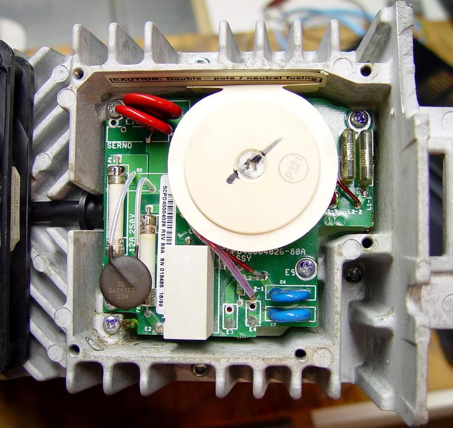
If you see components and something like this then you have an MTR2000 supply: (click for a larger image)
 .
.
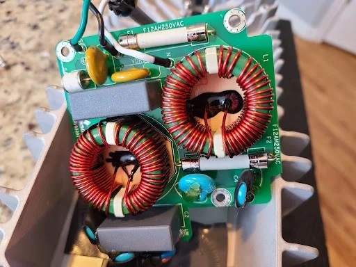
If you see the foil side of a circuit board then you have an MTR3000 supply.
Here's a photo of the MTR3000 board flipped over (component side). (click for a larger image)
 .
.
First: On this circuit board you will see two two AC power input fuses. They are the white cylinders on the left side of the MTR2000 board photo. The MTR3000 board also has two fuses, one is at the top of the photo. On both boards they are soldered in and it will not be quick and easy. If necessary replace them.
Second, you should see a metal-oxide-varistor (MOV) that is across the AC input line (in the MTR2000 board photo the brown device that is on top of the fuses is the MOV, it could be any color). The MOV in the photo is labeled "KCC 1314270-02" and that could be Keystone Carbon Company. I could not cross that to any current Mouser or DigiKey part (a part number that could be referenced to DigiKey or Mouser would be appreciated here…) If the MOVs has failed it should be readily apparent as it will be visually discolored or burnt up.
Third: you will see a white cylinder on the MTR2000 board. In some units it looks like a fiberglass and silicone sock. It contains a thermistor that limits the inrush current as the main filter capacitors charge up. When the inrush thermistor in an MTR2000 fails it is in a dramatic and spectacular way and there isn't much left behind to get a part number from. Having a flameproof sock or housing around the part contains the pieces, the drama and any damage.
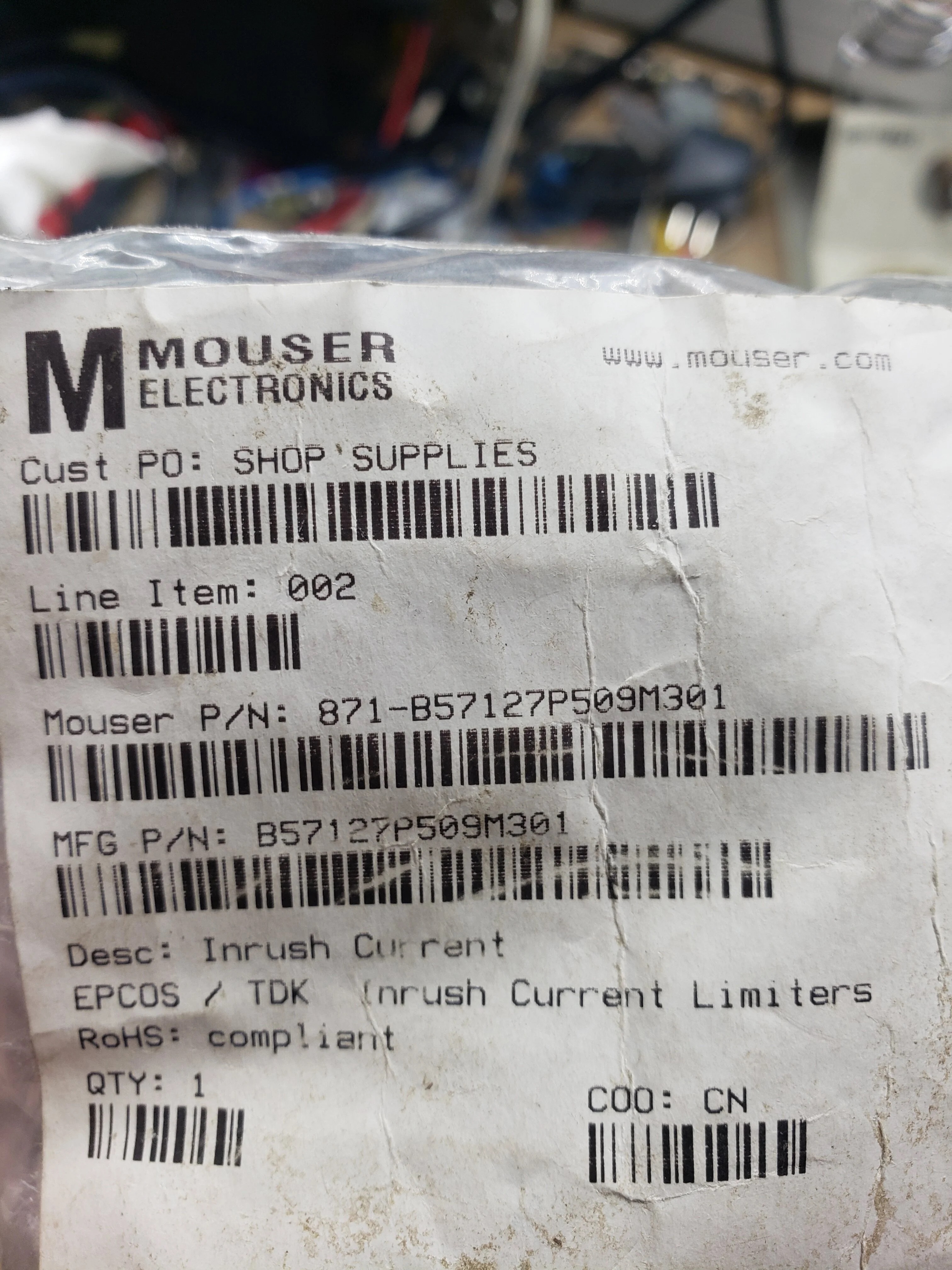
The replacement thermistor is a TDK Electronics B57211P0809M301,
the DigiKey part number is B57211P0809M301-ND, the Mouser # is 871-B57127P509M301.
Here's the data sheet.
DO NOT forget to put the white housing back over the new thermistor before you apply power.
Fourth: The next most common failure in these supplies beyond the MOV's
and the inrush thermistor are the electrolytic capacitors. They
break down internally over time.
One possible symptom is that the supply will be pulsing on and off, never quite
starting up and reaching run mode but attempting to start over and over.
One possible debug technique is feeding the DC input with the normal +12 or
+28 volts from a known good source and then trying to start the supply.
If the supply starts at that point then swap ALL the electrolytic caps in the
supply. The supply uses a number of 200µF 680 Volt
caps and a number of smaller ones.
(photos and a parts list would be appreciated here)
David Ranch KI6ZHD sent an email describing the repair to an MTR power supply that would not start:
I recently repaired a failed MTR2000 repeater that came to me without any LEDs lit up on the chassis.  It had an MTR3000 style power supply.   This failure most likely happened
during a recent power outage where there was a downed power line and the equipment was only receiving 67 volts of AC for over a day before the power company repaired the line.
The ultimate failure was the AC power supply's starter capacitor (full details below).
In addition to this capacitor fix, I gathered some additional details that might be helpful to put on your Repeater-Builder MTR page:

  - Tear down of the MTR3000 Astec 042-70109601B 500w AC power supply made in 2004:
      - There are a LOT of different screws used on this unit (lengths, Torx versus philips, etc)
         so create a plan to keep track of it all.  There can be 40+ screws involved.  An electric
         screwdriver will be useful.
      - On top of the four SCRs are little plastic inserts.  Pull them out before they fall out and
        you loose them.
      - Once the case is split apart, on top of the copper heatsink plate where the four SCRs meet,
        there are three little plastic o-rings.  Pull them out before they fall out and you loose them.

  - Notice:
      - The two fans on the unit are:  Superred 120mm x 120mm x 25mm 12vdc @ 0.38A,
         part number: CHB12012CB(E) - 2 pins with no tachometer signal.
      - I found some PCB heat discoloring around D211 and T201.

  - Troubleshooting:
      - The power entry box on the outside of the power supply is where two AC fuses and
         the troublesome inrush thermistor and other MOVs are located.  This MTR3000
         style PCB where all the components are facing CAN be pulled out a bit without full
         disassembly of the power supply from the chassis to inspect but you will need to
         remove the fan to loosen up the AC power cable to give slack to the filtering PCB.

      - This power entry PCB has TWO glass tube AC fuses that are soldered on.  I didn't need
         to replace them so don't have their specs but it will take a very hot iron to unsolder the
         fuse caps to get them out.

      - Glass signal diodes D211 and D218 on the bottom of the PCB toned out with a "short"
        but this seems to be normal as I pulled them and they tested ok yet the low resistance
        path is elsewhere on the PCB.  They are unmarked and I have no idea what their part number is.

      - The ceramic blob-style power diode D206 on top of the PCB will tone out with a short
        but this is normal as I pulled them and they tested ok yet the low resistance path is
        elsewhere on the PCB.  There are some markings on the body of the diode but I wasn't
        able to get get them.

  - Repair
      - I solved my no-start issue by replacing C280, the starter capacitor.   It is located between
         the two main filter capacitors. The old one was 22uF at 35 volts and made by Taicon,
         and upon removal it had an ESR of 6.7 Ω per my BlueESR meter.  I replaced it
         with a 22uF 50v 105C rated device (use Mouser part number 710-870235673001)
        with a measured ESR of 1.2 Ω (the LOW ESR part is REALLY important on this part).
        I then reassembled the whole chassis with new thermal grease and IT WORKS!

PS: We had a previous power outage at the site and this MTR2000 didn't come up on AC power
       restoral.  I had simply pulled the A/C power plug and put it back in and it started up.
       On hind sight, maybe this was a symptom of the failing starting capacitor.
David mentioned that his MTR was seeing only 67 volts of AC for over a day before the
power company repaired the line. I've seen that AC voltage problem before... A number of years
ago a local AM broadcast transmitter site lost a phase on their 3-phase power line feed. They
were seeing about 67 to 69 volts on all of the station wall outlets. As soon as the phase was restored
the voltage at the outlets instantly returned to the 121 volts of AC that was normally there.
Power supply details (in case these numbers help anybody):
|
The DC input of the low power (40 watt) station is designed for 14 volts DC at 12 amps, the high power (100 watt) stations are rated at 28.4 volts DC at 13 amps, both are negative ground. That's ratings, I measured one of my 100 watt UHF stations and it draws 11 amps DC at 28V DC when making 70 watts out.
Two things to consider if you chose to get around a failed MTR suply and run the repeater from DC…The MTR power supply generates an "AC Power OK" signal that goes to ground to indicate you have AC present, or pulled to +5vDC if not. It only affects the way the station reports errors or chooses to run on lower power when on battery.
1) The MTR has two programmable RF power levels, one for AC input and one for DC input.
The unit will believe it's running on battery and the repeater will drop the RF output power to whatever the RF power setting is for DC operation.
2) There is an alarm function for running on DC… You will need to disable that alarm in the RSS / CPS.
DC Power:
The DC power input connectors on both the low power (14 volt 40 watt)
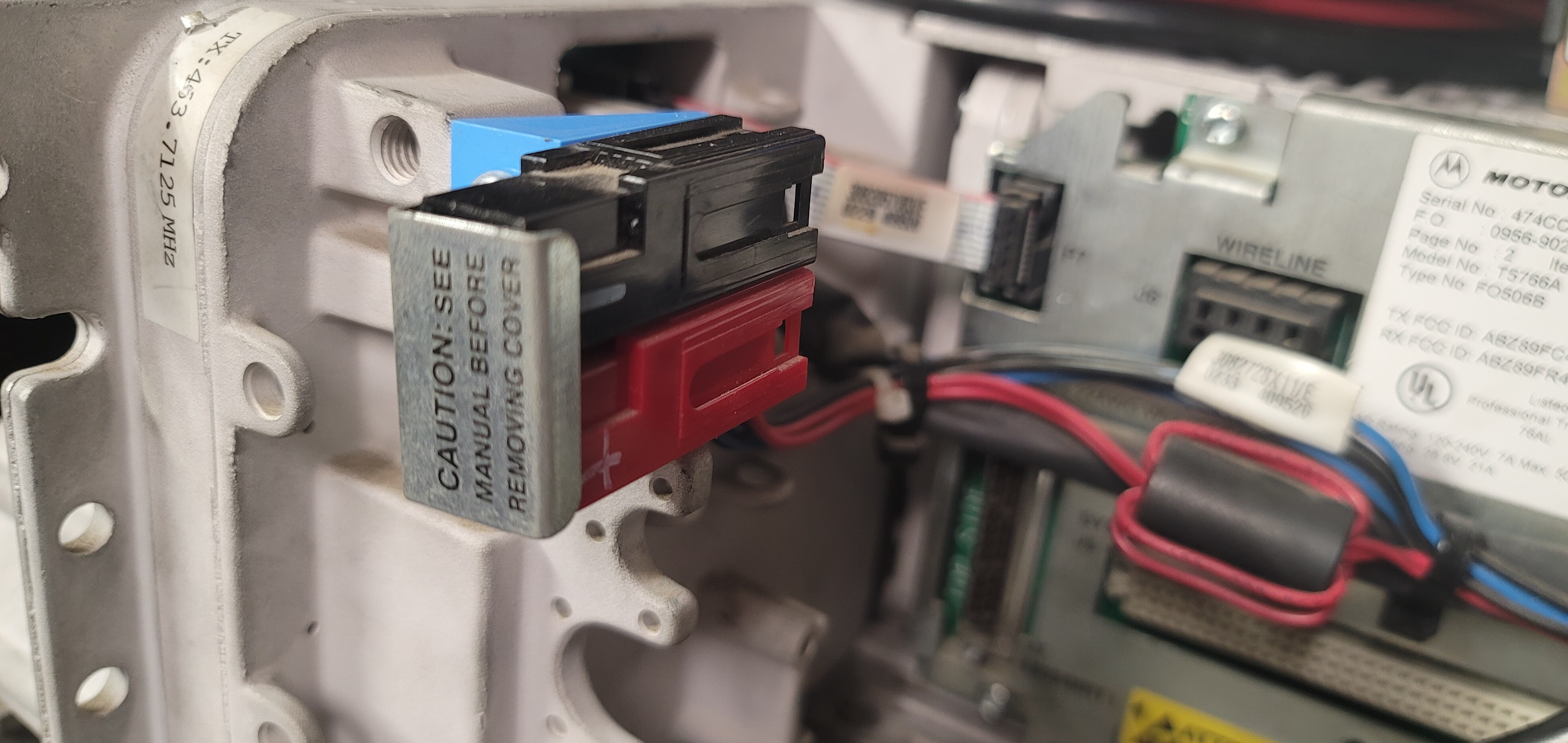
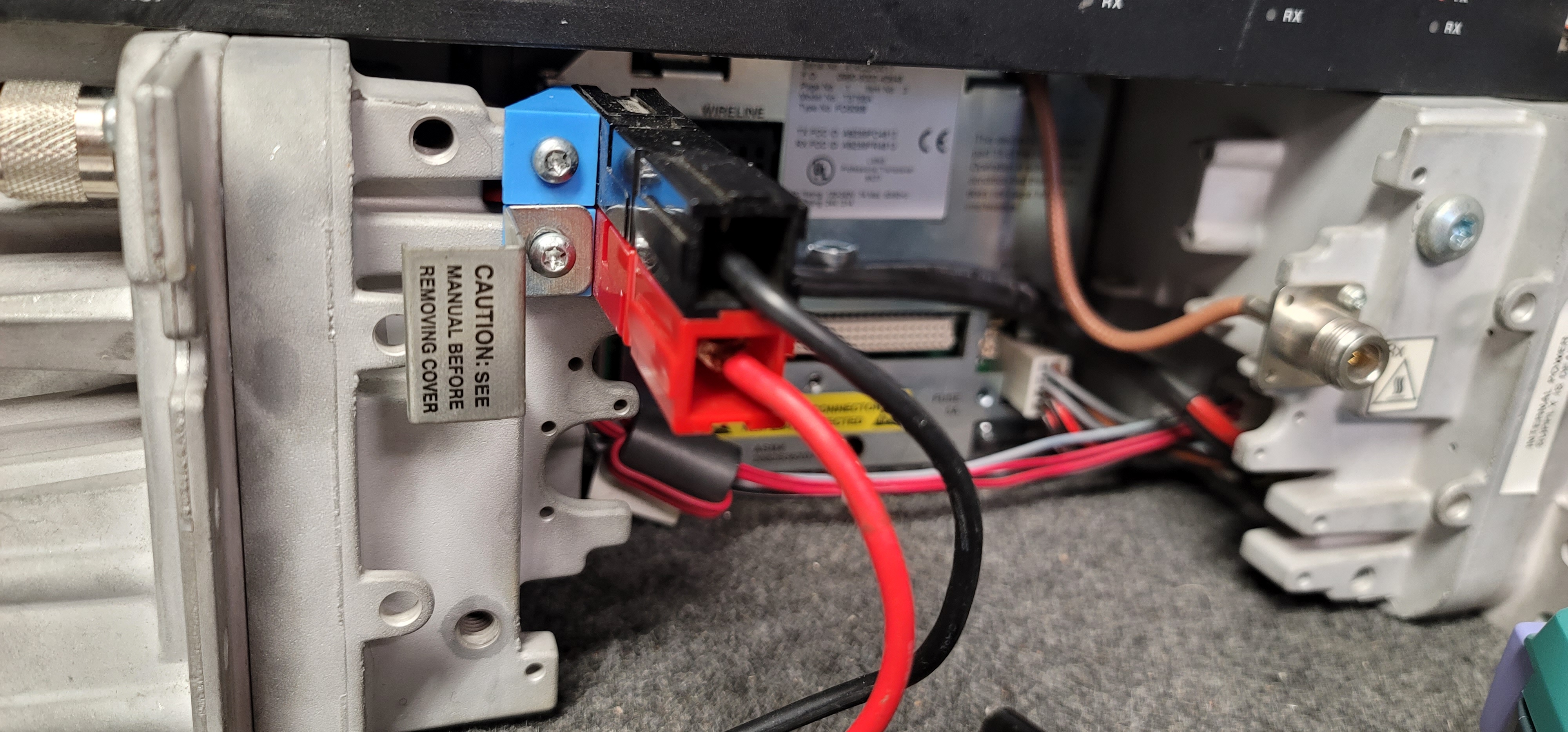
and the high power (28 volt 100 watt) stations use a red / black
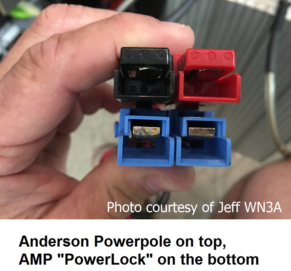
AMP / TE connector pair. They are not Anderson PowerPoles!
Look for a red / black connector set on the back of the MTR. They are
stacked vertically with black on top (see photos below). Personally,
I feel that Moto should have used red / black for 12v and
blue / black for 28v. Yes, blue is available, see below.
From looking at the block diagrams in the manuals that are available it looks like the
battery revert connector / DC input connector on the power supply connects
inbetween the step-down stage and regulator / filter stage in the supply,
without the benefit of any isolation diodes. As a result, there is always station voltage on
the backup power connector.
As a result, any backup system (including the factory specified Argus battery revert unit
for the MTR (which is a a battery switch and charger / conditioner in one unit)
must include a disconnect relay for the battery bank. While AC mains power is present the
Argus unit completely isolates the battery from the repeater. Upon AC failure the Argus
disconnects the batteries from the charger / conditioner ciruit and connects
the batteries to the MTR. The process is fast enough that the repeater doesn't do a power-on
reset. The battery charger / conditioner inside the Argus is totally isolated
from the MTR2000.
The MTR station backplane includes both logic level and Nomally Open contact
closure outputs for mains AC fail that can be used to control higher power relays.
The low power MTR AC power supply outputs about 14.4v DC which is higher
than most battery float voltages, the high power supply output voltage is about twice that.
So leaving a battery directly on the MTR DC revert terminals will cause overcharging
and damage…
Then when AC power is restored the power supply sees a very discharged battery
that can look like a short, and the overcurrent can damage the MTR power supply
switching / filter stage(s).
The DC power input connector on the back of an MTR2000 is normally covered with a
Motorola-provided cover plate which can be swung out of the way (and not get lost).
If you lose it the replacement is a 1583305X01 "Cover, Power Lock Connector".
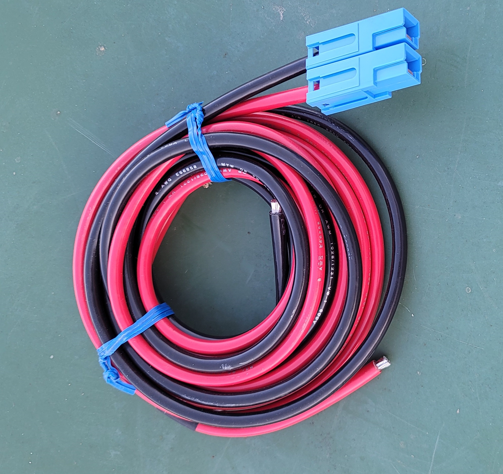
The official MTR / Quantar DC power cable is part number 3082009X02,
which is packed with a new station or can be purchased as a service part for about $40 (early
2023 price). It is 10 feet long, with #8 AWG stranded wires, one black and one
red, both terminated in a 75 amp Tyco / AMP / TE Connectivity
"Power Lock" series connector. The other end has a 30 amp cartridge fuse
in the red wire, one foot from the stripped end.
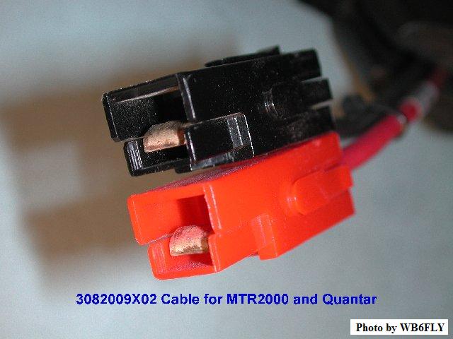
The above photo shows how you need to configure the 75 amp PowerLock
connectors on the #8 AWG DC cable so it will mate with the MTR2000
or the Quantar system DC connector.
DC Power Cord Caution:
As said above the MTR series DC connector set is NOT from the Anderson PowerPole family!
Quantars use a similar DC cable and your author found such a cable (photo) with two blue plastic shells and no fuse holder at the Dayton Hamfest. The seller claimed the cable was shipped with a medium power VHF Quantar base station.
If you are going to make your own cable the available shell colors (at the time of this writing) are red, blue and black. Note that the low power station uses +12 volts and the high power station uses +28 volts. Your author's personal opinion is that if you are making a cable for a 12 volt low power station you'd use red and black, and you'd use blue and black for a 28 volt high power station.
| Component | AMP Part Number |
Digi-Key Part Number |
Mouser Part Number |
|---|---|---|---|
| Red plastic shell | 53884-4 | 53884-4-ND | 571-538844 |
| Black plastic shell | 53884-3 | 53884-3-ND | 571-538843 |
| Blue plastic shell | 53884-1 | 53884-1-ND | 571-538841 |
| AWG size 6 to 10 silver-plated "Power Lock" crimp contact (two needed, assuming that you don't ruin one as you learn…) |
54330-1 | 54330-1-ND | 571-543301 |
Articles and Other Information:
|
|
Some notes on the MTR2000
by Eric Lemmon WB6FLY (SK) Read this article before buying either a new or a second-hand MTR2000. It contains some excellent information including an important caution to anyone contemplating buying an MTR2000. |
|||||||||||||||||||||
|
|
When interfacing an MTR2000 station to ANY external repeater, D-STAR, DMR, or
MMDVM controller, make sure you've set the station configuration (Repeater / Base)
to BASE so the station looks like a fully independent full duplex receiver and
transmitter. This configuration setting removes the internal repeater controller from
the audio and PTT paths. A couple of bonuses if you chose to use an external controller: 1) You can have remote shutdown via DTMF. 2) Some controllers have logic inputs… two could be connected to the MTR AC Power fail (i.e. on battery) output on pin A4, and an VSWR fail output (i.e. an antenna problem) on pin A10 and announce the failure with a speech message if the controller has a speech feature, or change the ID message or the courtesy beep if it doesn't. |
|||||||||||||||||||||
|
|
If your station has a Wireline board, even if you aren't using it, make sure
you set it to 4-wire. If set to "2-wire" mode the receiver audio will be muted when
the transmitter is active, because the 2-wire configuration only lets one audio signal
pass at a time. This is crucial when the station is configured as a "BASE" and an
external repeater controller is being used. NOTE: There are three wireline boards in the MTR2000 selection list (TTN5066, TTN5067 and TTN5068) and others in the MTR3000 list, make sure you select the correct one! Look at the Station Configuration Report screen for the exact model number of the board that is in your station, then select that number and set it to 4-wire mode. |
|||||||||||||||||||||
|
|
If you're interfacing an MTR2000 station using the MRTI connector, make sure you've set the External PTT Mapping on the Channel Information / PTT screen to "Microphone". When the MRTI PTT input is grounded, MRTI TX Audio replaces the front panel microphone audio as the input to the exciter. | |||||||||||||||||||||
|
|
Moto recommends that you use the "System Connector Kit" from Motorola, part
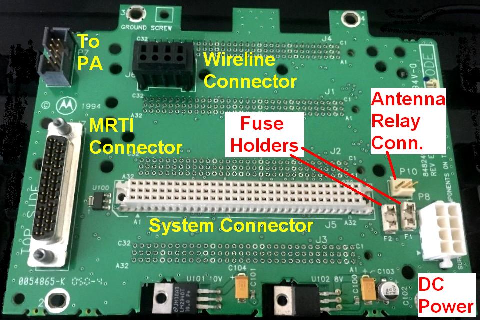
number 3083908X02 rather than mess with mismatched connectors from Digi-Key or Mouser. Personally, I suggest that you buy the adapter board from Dave WA1JHK – it's well designed, well made, has everything and is much easier than sourcing the parts and making your own. See the next bullet point down on this page. If you do chose to make up your own cable then you can get the connector shell and pins from Mouser, DigiKey or Newark. CAUTION 1: the pins snap into the connector body and are almost IMPOSSIBLE to remove once inserted. I broke off the pin for COS... I ended up cutting the cable, throwing away the connector body with the installed pins, buying a new body, more pins and starting over. CAUTION 2: Ignore the pin letters and numbers molded into the connector body. Two different emails reported that the designations molded into the connector bodies DID NOT match how Motorola used them. One suggested using a fine tip Sharpie pen to label the A-B-C rows, pins 1 and 32 and a line at pins 5, 10, 15, 20, 25 and 30.
|
|||||||||||||||||||||
|
|
There are several ways to use an MTR as a ham or GMRS repeater. If you chose to use
any external controller (like an RLC, Arcom, or Scom) via the 96 pin System Connector you
will discover a known "gotcha!" that the station does not transmit PL when using
the auxiliary audio input (which can be set for either normal or flat audio) and EPTT (External
PTT) on the System Connector. This is a firmware issue inside the MTR and there is no
"patch". You will need to sum (mix) your external PL encoder audio and the transmit audio and then inject the mixed audio into the aux audio input pin. When Motorola offered a paging version of their MSF series station Zetron created their own integrated summing amplifier and built it into a cable (part # 950-9919). Motorola relabeled it as the CDN6351 Zetron interface kit (other web pages say CDN6321 but they are wrong). But try and find one… I could not even find the schematic… When you create a summing amplifier you should have separate level controls for the PL encoder and the repeat audio so that you can get the mix "just right". You should also have a CTCSS high-pass audio filter in line with the repeat audio to keep any artifacts out of the sub-audible range. The JHK Labs interfacing board has this as an option. |
|||||||||||||||||||||
|
|
The COS / COR and CTCSS Detect outputs of the MTR are active high and there is no RSS option for active low. They are logic outputs and CANNOT drive relays directly. This is a "so what" with most modern controllers as they can be configured to accept active low or active high. If your external controller requires active low then you will need to invert them with your own interfacing circuitry. The JHK Labs interfacing board has the option of inversion on both the COS and PL / DPL Decode signals. | |||||||||||||||||||||
|
|
ICS Controls makes a simple adapter board that plugs into the same System Connector
as the one above. It has a 9-pin "DSUB" interface connector
for connections to an external device – an Allstar board, a paging controller, a repeater
controller, etc.
Photo 1
Photo 2
Photo 3. Each
of the photos will open in a new browser tab).
Pin 1 of the 9-pin connector is acccessible on a pad for one custom connection (in one of the
photos the orange wire is connecting the VSWR signal to the pin 1 pad) and pins 6, 8,
and 9 are all ground. If you want you can cut a trace and free up pin 6 for another connection,
however you should do that before you mount and solder the 9-pin connector.
Click here for the ICS MTR2000 page
(opens in a new browser tab).
You want the one that has the 9-pin "DSUB" connector and both the 5-screw
terminal block and the 2-screw terminal block (which outputs +12 volts to power an external
controller). At the time of this writing the photos on their web site do not show that version. |
|||||||||||||||||||||
|
|
Interfacing the MTR2000 to an external controller (Arcom RC210) by the Reno Ham Radio Club W7RHC. | |||||||||||||||||||||
|
|
A better way
to interface the MTR2000 to an external controller by by Matthew Littleton
KN4SWB. Not thrilled with the other interfacing methods, Matt figured out a way that lets the MTR2000 handle PL / DPL while the external controller does everything else. While he used an Arcom RC210, this method can be used with the other common repeater controllers. |
|||||||||||||||||||||
|
|
Interfacing the MTR2000 to an external controller (a CAT250) originally written by Robert Shepard in 2004, who later asked that it be removed. It was recovered, modified, and resubmitted by Robert Meister WA1MIK. | |||||||||||||||||||||
|
|
Interfacing the MTR2000
to an external controller (CAT200B) by Robert W. Meister WA1MIK Yet another way of interfacing an external controller to these stations. This one uses the MRTI connector to get around the PL / DPL problems that arise with the other methods. |
|||||||||||||||||||||
|
|
External Controller Interfacing
Summary by Robert W. Meister WA1MIK A summary of the connection points and available signals to interface any external repeater controller. The information was extracted from other articles here and from info found on the web. |
|||||||||||||||||||||
|
|
Configuring an MTR3000 for Analog
Allstar Operation by Stephen Gansky W3AAD Steve interfaces a MTR3000 to an Allstar USB-to-audio adapter however interfacing an external controller like an Arcom, Scom or RLC uses the same connector, signals and pins. |
|||||||||||||||||||||
|
|
Making a MaxTrac and MTR2000
Dual-Purpose Programming Cable by Robert W. Meister WA1MIK Why spend $25 or more for a gutless programming cable? Modify your existing cable to do double duty. |
|||||||||||||||||||||
|
|
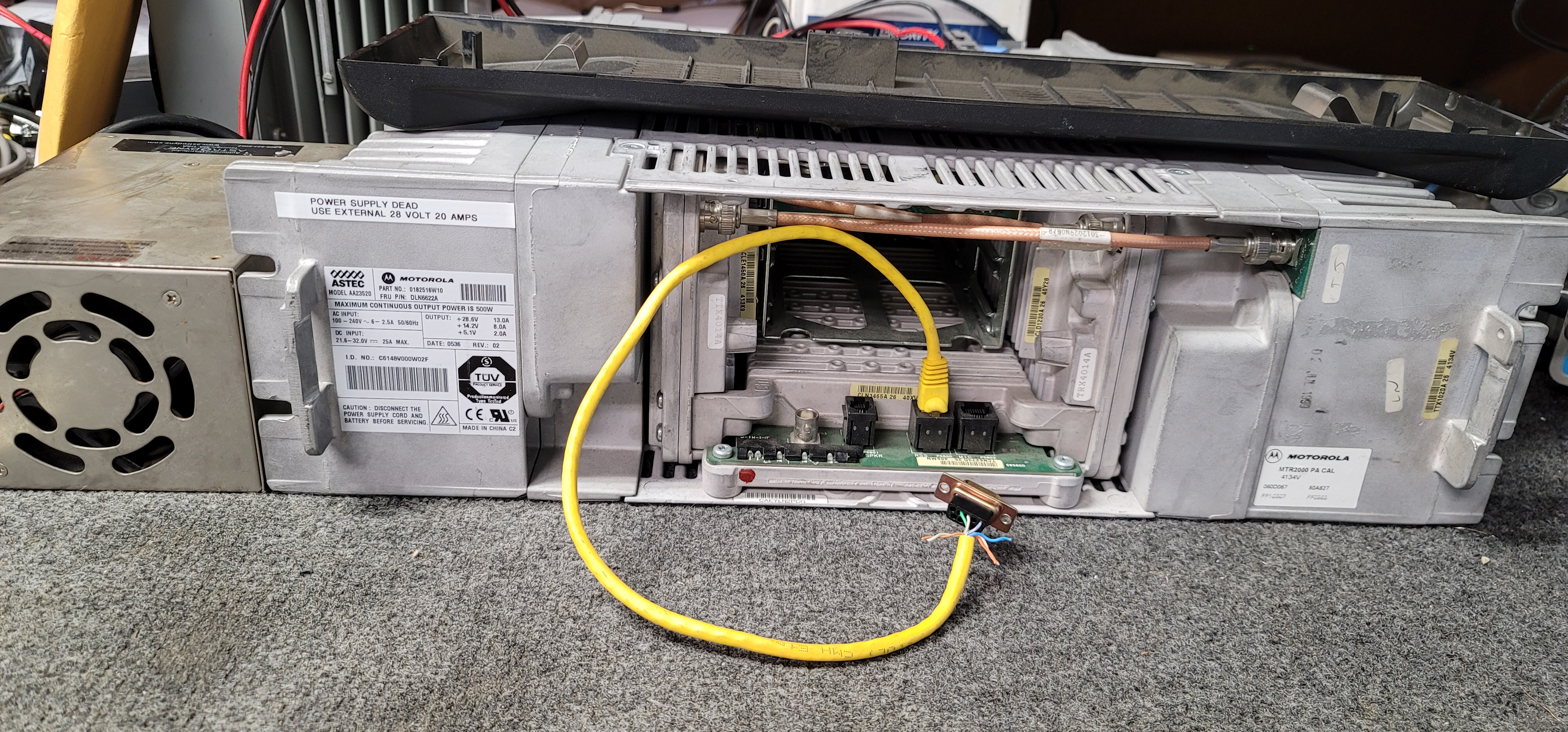
A Photo Tour of a 100w UHF MTR2000
Repeater by Robert W. Meister WA1MIK Bob came across one that was being thrown in the dumpster and it was filthy and full of rodent and bird droppings, fur, feathers, and nesting material. He washed everything and took some detailed photos of the innards. The power supply was shot. The station works fine with an external 28 volt, 20 amp supply. |
|||||||||||||||||||||
|
|
The MTR2000's Modular
Connectors by Robert W. Meister WA1MIK Pictures and pin descriptions of the modular jacks behind the front cover. |
|||||||||||||||||||||
|
|
The MTR2000's Backplane
Connectors by Robert W. Meister WA1MIK Pictures and pin descriptions of the connectors on the rear of the station. |
|||||||||||||||||||||
|
|
Making the MTR2000 Operate in the 900 MHz Amateur
Radio band by Robert W. Meister WA1MIK The MTR receiver programs from 896 to 915 MHz as-is and that works fine, a few easy hex-edits extend the MTR transmit range from 935-941 MHz down to 925-941 MHz. |
|||||||||||||||||||||
|
|
Making the 403-435 MHz MTR2000 Operate
up to 440 MHz by Robert W. Meister WA1MIK A few easy hex-edits extend the TX and RX range from 403-435 MHz to 403-440 MHz. |
|||||||||||||||||||||
|
|
Making the 100w VHF 150-174 MHz
MTR2000 Station Work in the 144-148 MHz Amateur Band A cooperative effort by
Robin Feil W7MSE, Scott Lichtsinn KBØNLY, and Robert W. Meister WA1MIK. The VHF receiver and exciter are 132-174 MHz, and the low power (30-40 watt Power Amplifier module is the same. The 100 watt PA comes in two ranges: low range (132-154 MHz), and high range (150-174 MHz). A resistive voltage divider inside the high power amplifier generates a specific DC voltage on one of the conductors in the cable between the PA and the exciter and that voltage informs the exciter if the PA is low power or high power. The exciter then informs the station control board. This article describes how to modify the high power 150-174 MHz power amplifier so it lies and tells the exciter that it's a high power 132-154 MHz unit… and that fakery enables the 100 watt MTR transmitter to work below 150 MHz. |
|||||||||||||||||||||
|
|
A List of Module Numbers in the MTR2000 by
Eric Lemmon WB6FLY (SK) In some cases the only way to determine what you have is to inventory the Field Replaceable Units (FRUs). This list was compiled from the MTR manuals and the CPS help screens. |
|||||||||||||||||||||
|
|
Programming the transmitter idle
frequency on the MTR by Eric Lemmon WB6FLY (SK) What to do when exciter/transmitter local oscillator leakage is a problem (this is mandatory if you are running an MTR on a simplex channel, and nice when on a repeat channel and you are local to the site). |
|||||||||||||||||||||
|
|
Setting up the MTR2000 for Battery
Backup by Eric Lemmon WB6FLY (SK) Especially when you are on a budget… If you are thinking about connecting ANYTHING to the external DC connector on the back of the MTR (the PowerLock connector) then you will want to read this article! |
|||||||||||||||||||||
|
|
W9CR's MTR page contains even more MTR tidbits and helpful information. |
From an email to repeater-builder… a note on setting up an external repeater controller:
The MTR is a nice unit, and the internal controller will do 80%-90% of what most amateur systems need to do. For those that need more the unit has a connector on the back that is called the "System Connector" and a second connector designed for the "Mobile Radio Telephone Interconnect" (MRTI) unit and all the interfacing can be done through one or the other.
One quirk: the microprocessor in the station will not pass its own power-on self-test with the transmitter PL encoder inhibit line (pin 24 of the the 25 pin MRTI connector) grounded (i.e. active). So if your needs include switching the internal PL encoder on and off (it's a handy thing to have through a controller output to use for level setting), when you configure your repeater controller you need to set up a timer to make sure that this line is not asserted until after the self-test is finished. The simplest way is to use a timer in the controller's start-up macro to inhibit all repeater operation for the number of seconds that the self test requires, plus one or two extra. This quirk may also apply to other logic input signals on the MRTI and System connectors, depending on your station's firmware version and station configuration.
Manuals, Data Sheets, and Other Documentation:
|
|
The original MTR2000 VHF and UHF catalog sheet 73 kB PDF file This is a PDF of the original glossy catalog sheet. |
|
|
the original MTR2000 800 MHz and 900 MHz glossy catalog sheet 148 kB PDF file This is a scan of an original paper catalog sheet. |
|
|
An MTR2000 Product Planner and Ordering
Guide 300 kB PDF file This document describes the various options available when a station was to be ordered brand new. Lots of useful details here. |
|
|
The MTR2000 Installation and Operation Manual 2.4 MB PDF file Just what it says. Manual 68P81096E20-N dated 2005-Jun-28. |
|
|
One of the options on the MTR was a 3 pole TLE5992 or CLE1170 (or CLE1170B)
preselector module that was mounted on the
back of the MTR chassis and cabled between the receiver module and the receiver antenna
connector. The receiver module is varactor tuned, this preselector is mechanically tuned.
The measured insertion loss is about 1.2 dB and it's spec'd at 4 MHz wide. The one I
measured was about 5 MHz wide. Note that the stations that were built with the preselector use a different receiver module than the stations that do not have the preselector. MTR2000 Preselector Tuning probably from the MTR2000 Basic Service Manual 300 kB PDF file Extracted and PDF'd by Eric Lemmon WB6FLY (SK). Additional information can be found on the RSS Help screens. |
|
|
Preselector Tuning from the MTR3000
Basic Service Manual 1.5 MB PDF file A bit more detailed than the above. |
|
|
An MTR3000 Product Planner and Ordering Guide 1.9 MB PDF file Even though this is for the newer MTR3000 station, there's still a lot of useful stuff that applies to the MTR2000 here, since you could field convert your MTR2000 to an MTR3000. |
|
|
The original MTR3000 Specification / Sales sheet 208 kB PDF file. |
|
|
A comparison of the major differences between the MTR2000 and the MTR3000 185 kB PDF file. |
|
|
What's in the TRBO conversion kit that turns an MTR2000 into an MTR3000 2.4 MB PDF file. |
|
|
VHF duplexer
options 1 MB PDF file. One of the options from Motorola for the low power VHF MTR2000 is an in-cabinet duplexer. The unit that Motorola supplies is a relabeled Celwave model PD5042-1 and requires at least 1.5 MHz separation (offset) between the receiver and transmitter. This unit will NOT do the 600 KHz separation that amateur 2 meter repeaters need! |
|
|
UHF duplexer
options 1 MB PDF file. One of the options from Motorola for the low power UHF MTR2000 is an in-cabinet duplexer, part number 0185417U05. The unit that Motorola supplies is a relabeled Celwave model PD526-4-2 that has 6 cavities, can handle 250 watts, provide over 100 dB of isolation, with a minimum of 3 MHz separation from 438-470 MHz. It was offered for the MTR2000, Quantar and Quantro stations, probably more. |
|
|
Motorola Field Service Bulletin
FSB10174 donated by by Eric Lemmon WB6FLY (SK). 100 kB PDF file. Issue 1: MTR2000 station locks up in transmit with no PL. Issue 2: MTR2000 station does not transmit an analog audio on wireline line 2. Motorola has identified a firmware issue in all versions prior to and including version R03.04.002 and has a warranty fix. The PDF file linked above includes a software order form Note: The replacement firmware was keyed to the station backplane number (essentially an electronic serial number). The order form is useles since the MTR is discontinued and replacement firmware is unavailable. |
|
|
The Argus Switched
Mode Charger donated by Eric Lemmon WB6FLY (SK). 1.43 MB PDF file. The Argus Technologies model #010-519-20 is intended for the 30 watt and 40 watt MTR2000 stations that operate on 14 volts (Motorola calls it the L1883); the #010-523-20 model is used with the 75 and 100 watt stations that operate on 28 volts (Motorola calls it the L1884). Either one is a much more complicated device than its catalog description implies, perhaps justifying its significant cost ($1451 new, dealer cost is $1222 in 2004). The MTR has full power supply voltage on the battery terminals while it is connected to AC mains power. The Argus unit is cabled between the MTR and the battery, one connection to the battery and a separate connection to the MTR. As noted in the manual, it must be used with an MTR2000 that includes an internal power supply, since its purpose is to provide only a charging and equalizing function for the backup batteries, along with various alarm and monitoring capabilities. There are relay contacts in the Argus to isolate the battery from the MTR until there is a power failure. There's an interesting Argus discussion here. (off-site pointer, opens in a new browser tab) The Argus manuals state that it must be connected to the MTR2000 with the following items:
|
|
|
Argus 14 volt, 20 amp battery charger 750 kB PDF file For 40 watt stations. This came directly from Argus. |
|
|
Argus 28 volt, 10 amp battery charger 750 kB PDF file For 100 watt stations. This came directly from Argus. |
|
|
Motorola HSN1000A Amplified
Speaker Instruction Manual Scanned by Eric Lemmon WB6FLY (SK). 410 kB PDF file. This speaker was originally designed for the MOSTAR product line and has been used in several product lines where an amplified speaker would be useful, like in a mobile charger for a handheld radio. The HSN1000B speaker is identical except that it uses surface-mount components inside. Both the A and the B model have been discontinued and the current replacement is the HSN1006. All of the connections are the same. The cable between the HSN1000 / 1006 speaker and the MTR is part # 0185180U01 and is covered in another document below. |
|
|
Motorola HSN1000A Amplified
Speaker Instruction Manual Scanned by Robert Meister WA1MIK. 2.9 MB PDF file. Same as above, only done with photographic quality and is therefore much larger. |
|
|
Motorola HSN1006A Amplified
Speaker Instruction Manual Scanned by Eric Lemmon WB6FLY (SK). 280 kB PDF file. The HSN1006A replaced the HSN1000A and B amplified speakers. |
|
|
Motorola 0185180U01 Speaker
Adapter Cable Diagram Drawn by Eric Lemmon WB6FLY (SK). 66 kB PDF file. This connects the HSN1000 / HSN1006 speakers to the MTR2000 / MTR3000 stations. |
|
|
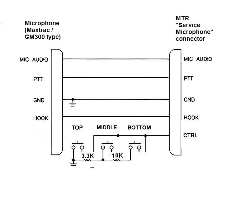
Motorola GMN6147B
Service Microphone Instructions Scanned by Eric Lemmon WB6FLY (SK). 110 kB PDF file. The three-buttons on the side of the microphone are used to do things like open the squelch and adjust the speaker volume on the MTR2000/MTR3000 stations. Update: the GMN6147 has been replaced by the GMMN4063B. Here is a schematic of a homebrew test microphone adapter that gives the exact same functionality as the GMN6147 or the GMMN4063B to a regular Maxtrac or GM300 microphone. You could build your own adapter using three common pushbuttons, two resistors, and a box to mount the buttons into… even a Tic-Tac candy box. Then plug a regular microphone (i.e. a MaxTrac / GM300 microphone) into the box, and a second cable to connect the box to the MTR. The second cable could be a common ethernet cable. |
|
|
MTR2000 VHF Station Instruction / Field Service Manual 68P81096E30-F (dated 08/06/07) 7.9 MB PDF Contains information on the CLN1211 and CLN1212 receiver modules, the CLN1233 exciter module, the CLN1224, CLN1225, CLN1226 and CLN1227 power amplifier modules, the CLN1465 station control module, the CLN1203, CLN1204 and CLN1205 wireline interface boards, the CLN1206 auxiliary I/O board, the CLN1202 backplane board, the CLN1220, CLN1221, CLN1222, CLN1223, DLN6458, DLN6622 and DLN6624 power supplies, the CLN6680 antenna relay module, the CLN1216 and CLN1217 VHF external preselector, the CLN1207, CLN1208 and CLN1209 circulators, the TYD4031, TYD4032, and TYD4033 duplexors, and the TDN9946 repeater panel (a renumbered Zetron Model 38 community repeater panel, requires the CDN6351 Repeater Panel Interface Cable). |
|
|
MTR2000 Station Control Module CLN1465 Service Information 6881096E32-E (dated 08/06/07) 2.2 MB PDF (no schematics) |
|
|
MTR2000 Station Backplane TTN5062B Service Information 68P81094E31-E (dated 03/26/99) 946 KB PDF |
|
|
MTR2000 UHF Station Instruction / Field Service Manual 6881096E25-G (336 pages, dated 08/06/07) 8 MB PDF |
|
|
MTR2000 UHF Service Manual 6881096E35-A (166 pages, dated 01-05-97) 41.5 MB PDF |
|
|
MTR2000 800 and 900 MHz Instruction / Field Service Manual 68P81096E90-F (280 pages dated 08-06-2007) 6.46 MB PDF |
|
|
MTR3000 Basic Service Manual 68007024096-K (dated 08/2014) 25.2 MB PDF |
|
|
MTR3000 Detailed Service Manual 68007024097-A (dated 01/2010) 27.4 NB PDF You may not need this one as the next one is 2 years and nine revisions later… we don't know the equipment well enough to know if this version A (i.e. initial) manual has information the later ones deleted… |
|
|
MTR3000 Detailed Service Manual 68007024097-J.pdf (dated 11/2012) 57 MB PDF This is Version J of the manual above… |
|
|
MTR3000 Installation and User Manual 68007024098-H (dated 07/2011) 7.1 MB PDF |
|
|
MTR3000 SpectraTAC Voting Default Programming 308 KB PDF This one-page document shows the default programming settings for the MTR3000 wireline control via TRC settings for SpectraTAC Voting mode. |
|
|
RVN4148 RSS Manual version D. (68P81096E15-D) (65 pages, dated 06/28/2005) If anyone has a later edition we'd appreciate an emailed PDF. |
Back to the top of the page
Back to Motorola index page
Back to Home
This page created 06-06-2011 by Mike Morris WA6ILQ
MTR2000 and MTR3000 are registered trademarks of Motorola Inc., along with a bunch of other terms and no misuse, violation or infringement is intended.
This web page, this web site, the information presented in and on its pages and in these modifications and conversions is © Copyrighted 1995 and (date of last update) by Kevin Custer W3KKC and multiple originating authors. All Rights Reserved, including that of paper and web publication elsewhere.