Up one level (MTR2000 Index)
Up two levels (Main Motorola Index)
Back to Home
|
|
Making the 100w VHF
150-174 MHz MTR2000 Station
Work in the 144-148 MHz
Amateur Band
A Cooperative Effort by Robin Feil W7MSE,
John Case AD7SV, and Scott Lichtsinn KBØNLY
Compiled and written by Robert W. Meister WA1MIK.
Maintained by Mike Morris WA6ILQ.
|
|

|
Background:
The most common 100w VHF station covers the 150-174 MHz range. It will not work
below that, making it somewhat useless for amateur operation. There is a 100w version
that covers 132-154 MHz, but those are quite rare. There are also 30 watt and
40 watt VHF stations that cover the full 132-174 MHz range. The 100 watt Power
Amplifier (PA) assembly is the limiting factor in these stations. While they will physically
work slightly out-of-band, the firmware won't allow programming the station outside of the
150-174 MHz PA range. The transmit exciter and receiver will cover the full
132-174 MHz range. The receiver pre-selectors also come in two ranges but the
150-174 MHz unit can be tuned to cover the amateur band.
Some of the info in this article was posted on the web elsewhere, but it was
incomplete and lacked some procedural steps. This article addresses those omissions
and presents the information in an easy-to-understand way.
The conversion is done in two phases: hardware: two resistors are changed in the PA,
and software: the station configuration, programming, and alignment is done using RSS.
Before you start, make sure the station is properly and completely aligned, including
the deviation and modulation compensation. Program the station for transmit and receive
frequencies around 152 MHz (anywhere between 150 and 154 MHz), so they will be legal for
either PA range. Write the code plug to the station and also save it to disk. Attach a wattmeter
and dummy load, key the station, and record the output power as well, so you have a reference.
Click on any image below for a larger view.
Hardware Conversion:
The 100 watt PA informs the exciter as to what range it is using a simple voltage divider to
present a DC voltage to an A-to-D input on the exciter. We are going to change the voltage divider
in the high range PA deck so that it lies to the exciter that it is a low range PA.
You will need two 15,000 ohm SMD resistors, size 0805 or smaller, fine point soldering
equipment, and normal electronic hand tools. The original resistors are 1/16w (size 0603)
but those are awfully small and size 0805 (1/8w) will fit if you position them carefully.
While not recommended, you could probably find a way to use ordinary 1/4w leaded resistors,
but the solder pads aren't really suited for that style of component.
- Place the station on your work surface.
- Disconnect the BNC coax going from the transmit exciter to the PA input jack.
- Disconnect the power and logic cables from the PA at the rear of the station.
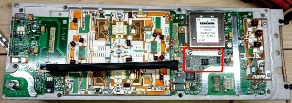
- You need to get inside the PA module. You can either detach it completely from
the station by removing six T20 flat-head screws that hold the PA to the card
cage covers then removing the eight T15 screws from the PA to separate it from
its heat sink, exposing the interior circuitry,
OR
Remove the eight T15 screws from the PA and gently remove the PA from its heat sink.
Refer to the inside photo below to see where you need to work.
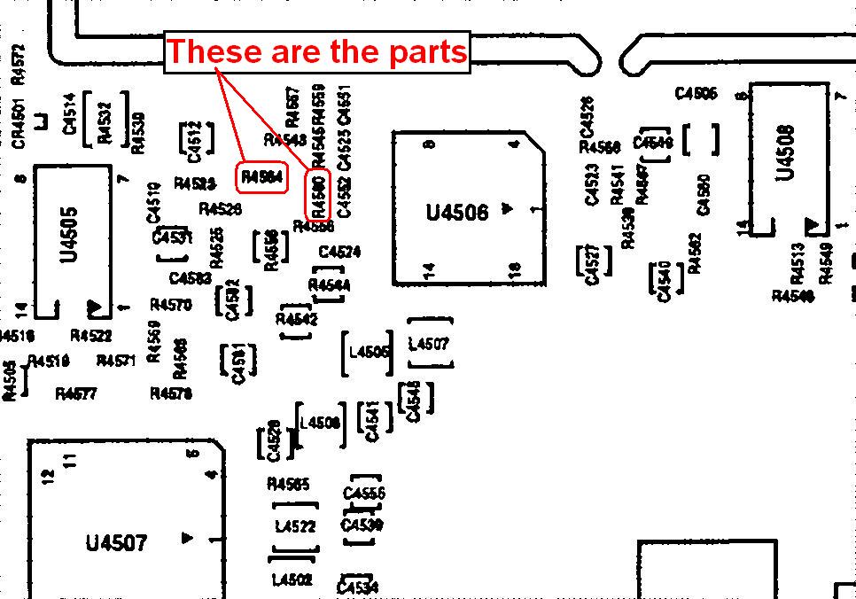
- Locate R4560 and R4564 by comparing to the close-up in the photos below.
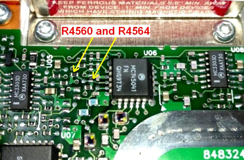
- Remove the two 1,500 ohm resistors (marked 152) at R4560 and R4564 from the
control board.
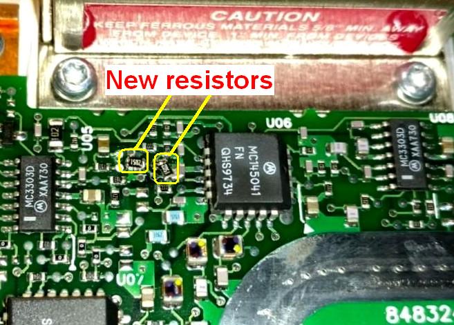
- Install two new 15,000 ohm resistors (marked 1502 or 153) at R4560 and R4564
on the control board.
- Clean the areas you worked on with some sort of flux remover. See the finished
photo below.
- Reassemble the PA heat sink using the eight T15 screws. If you had removed
the PA module from the station, reinstall it and secure it to the card cage covers
using the six T20 flat-head screws.
- Reconnect all of the cables going to the PA.
Software:
- Connect a wattmeter and dummy load to the PA output connector.
- Power up the station. You may get a red LED on the front panel because the station
expects a 150-174 MHz (high range) PA and the new resistor values make the station
think it's got a 132-154 MHz (low range) PA.
- Connect the programming computer and start RSS.
- Read the station's code plug and save it to disk.
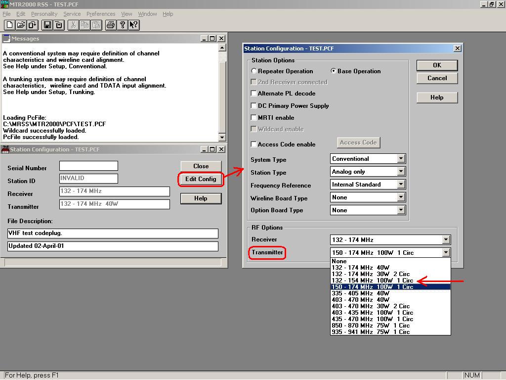
- Edit the configuration so the transmitter is the "132 - 154 MHz 100W 1 Circ" model.
See the screen shot below showing where to change the transmitter configuration in RSS.
- Write the code plug to the station and save it to disk.
- Verify that the station transmits at the original power by keying it with RSS.
- Reprogram the transmitter and receiver frequencies and tones to the ones you
want (in the ham band), write the code plug to the station, and save it to disk.
- Verify that the station transmits at the original power by keying it with RSS.
Some PAs may not make more than 75-80 watts at the 144 MHz end of the ham band. If
so, leave it there; no one will ever hear the difference.
- Connect a deviation meter or service monitor to the PA output and go through
the Deviation and Modulation Compensation alignment procedures, which are detailed
in the RSS Help screens. You only have to do the frequency ranges above 140 MHz,
as the PA may not perform properly if you go too far below 150 MHz.
Contact Information:
The author can be contacted at: his-callsign [ at ] comcast [ dot ] net.
Back to the top of the page
Up one level (MTR2000 Index)
Up two levels (Main Motorola Index)
Back to Home
This page originally posted on 06-Mar-2017
Photos © Copyright 2017 by Scott Lichtsinn KBØNLY
Article text hand-coded HTML © Copyright 2017 by Robert W. Meister WA1MIK.
This web page, this web site, the information presented in and on its pages and
in these modifications and conversions is © Copyrighted 1995 and (date of
last update) by Kevin Custer W3KKC and multiple originating authors. All Rights
Reserved, including that of paper and web publication elsewhere.