| Back to Home |
Daniels MT-2 and MT-3 Series Equipment Written by David VanHorn KC6ETE Compiled by Mike Morris WA6ILQ Maintained by Robert Meister WA1MIK and by Mike Morris WA6ILQ I know nothing about this equipment so please don't ask! |
One manufacturer that you don't hear much of in the amateur radio universe is the Canadian company Daniels Electronics, whose web site is at www.codancomms.com/lmr/.
In August 2012 Daniels Electronic was purchased by Codan
Radio Communications.
The formal announcement:
"On August 21, 2012, Codan Ltd. acquired Daniels Electronics Ltd. For legal, regulatory, financial and contract activities the company will be referred to as Daniels Electronics Ltd dba Codan Radio Communications.
It looks like most of the Daniels stuff is now listed as Discontinued.
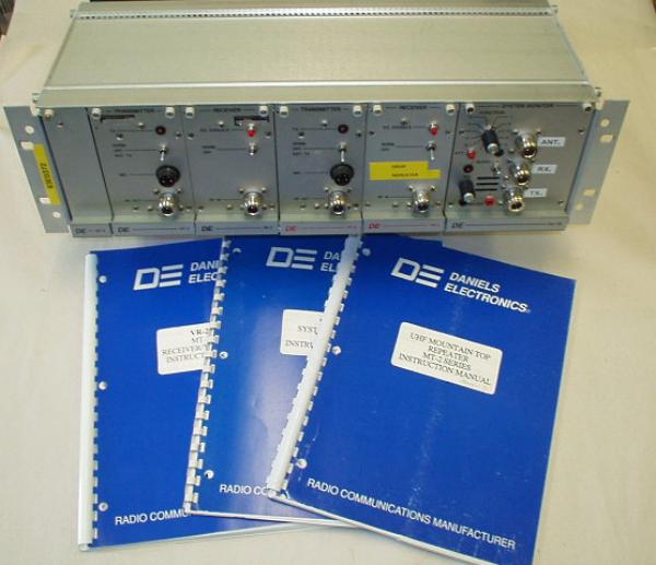
They are a manufacturer of some pretty high-reliability gear, typically used on extremely inaccessible sites, like remote mountaintops, or at the south pole! Their equipment is very pricey by ham standards, the system monitor card alone is roughly $500, and contains only some simple metering electronics, audio monitoring (an audio amplifier and speaker) and a +9.5 volt 5 amp regulator.
I've recently acquired two sets of Daniels equipment, and I'll be taking you through the process of converting them to ham use, for the US VHF and UHF ham bands. If I get really lucky, I might do the same with their 900 MHz gear, but I don't have that in hand yet.
Daniels has recently (2005) introduced their MT-3 systems, and has dropped support as of February 2005 for the MT-2 systems that I'll be talking about here. No documentation or support is available from Daniels for the MT-2 systems however Repeater-Builder recently received an anonymous PDF file that covers the VHF and UHF MT-2 equipment which can be downloaded here as a 7.7 MB PDF file.
If you get documentation with your system, you will notice that it is superb. Very nicely detailed, with theory of operation, alignment instructions, typical voltages, and real troubleshooting help.
When purchasing, make sure that the RF modules have their TCXO modules. These are small ice-cube shaped plastic (usually green) modules that contain the crystal, several thermistors, a coil, and a varactor. These modules would be rather difficult to duplicate. A module without its TCXO module is pretty much just spare parts.
Note from Reid W6MTF in June 2013:
West Crystal of British Columbia, Canada no longer makes radio crystals. Daniels was unable to recommend any crystal supplier, saying that West Crystals used a special fixture that was lost sometime after they went out of the crystal business. So far, ICM has not been able to temp-comp the Daniels TCXO modules and Bomar won't sell the service or the crystals, so you may have to try rigging another brand of module, such as a Motorola channel element or a GE ICOM into the Daniels equipment. There is a company in Eastern Canada that makes excellent crystals, Croven Crystals, but I doubt they would attempt temp comp on the Daniels equipment. By close examination of the TCXO, I can see Daniels used several temp-sensing resistors connected to temperature coefficient caps in the oscillator. To change the individual components they need a circuit diagram and some experience playing with the parts, and that's the problem: no one has a schematic or the experience.
System Overview:
A typical Daniels system starts with an M-3 Subrack.
RF and control modules plug into the subrack, and secure with locking fasteners. To unlock, simply turn 1/4 turn in either direction. The modules then slide out with minimal force.
RF connections are made to the front of the RF modules, and all other connections are made through the rear DIN connectors into the Subrack.
DC power comes into the back of the subrack by a pair of two terminal barrier strips, normally only the 13V pair is used. The rear of the rack offers two connections for repeater controllers, with one connector having access to all the signals, and the other having only a subset. More info on this in the subrack document.
Modules:
|
|
The MT-3 Subrack |
|
|
The VHF receiver module |
|
|
The VHF transmitter module |
|
|
The UHF receiver module |
|
|
The UHF transmitter module |
|
|
Repair and Overhaul of the UHF Receiver Front End |
Other Daniels and Codan MT-3 Manuals:
Some are Instruction manuals, others have full service information. Note that some of these have multiple revisions, indicated by the N-N-N sequence at the end of the manual's publication number. All are PDF files.
Test Procedures and Technical Notes:
|
|
Extender Card Instruction Sheet for SR-39 Subracks 42 kB |
|
|
Technical Note TN260-3 for Daniels UHF
Crystal Receiver 236 kB Specifications, models/bands, alignment. |
|
|
Technical Note TN262 for Daniels UHF
Enhanced Receiver 235 kB Specifications, models/bands, alignment. |
|
|
Test Procedure TN910 for Daniels
MT-3 using IFR COM-120 by Aeroflex 680 kB Subtitled: "Technical Note for Tuning, Testing Maintaining and Servicing MT-3 Analog Radio Systems with the IFR COM-120 (B or C) by Aeroflex". |
Aplication Notes:
|
|
Base Stations 1.5 MB Base stations: what they do, and the benefits in point-to-point communications. |
Conversion Articles:
|
|
Two-Meter Conversion of Synthesized VT-3 and
VR-3 by Gary Hendrickson W3DTN Converting the high-split transmiter and receiver to low-split for the two-meter amateur band. |
Back to the top of the page
Back to Home
Text copyright © 2005 by
Hand-coded HTML © Copyright 2005 Mike Morris WA6ILQ
This web page, this web site, the information presented in and on its pages and in these modifications and conversions is © Copyrighted 1995 and (date of last update) by Kevin Custer W3KKC and multiple originating authors. All Rights Reserved, including that of paper and web publication elsewhere.