Up two levels (Kenwood Index)
Back to Home
Compiled, HTML'd and Maintained By Mike Morris WA6ILQ

|
Up one level (Kenwood Repeater Index) Up two levels (Kenwood Index) Back to Home |
Interfacing to the Kenwood TKR-750, TKR-751, TKR-850, TKR-851, NXR-710 and NXR-810 Repeaters Compiled, HTML'd and Maintained By Mike Morris WA6ILQ |
|
Comments, suggestions, corrections to this page (actually to any page at this site) are welcome...
Just drop a note to the page maintainer... (even one that just points out a typo)
Note: On this page an "x", as in TKR-x50 means either 750 or 850, likewise on the TKR-x51s and the NXR-x10 means either the 710 or 810.
Background:
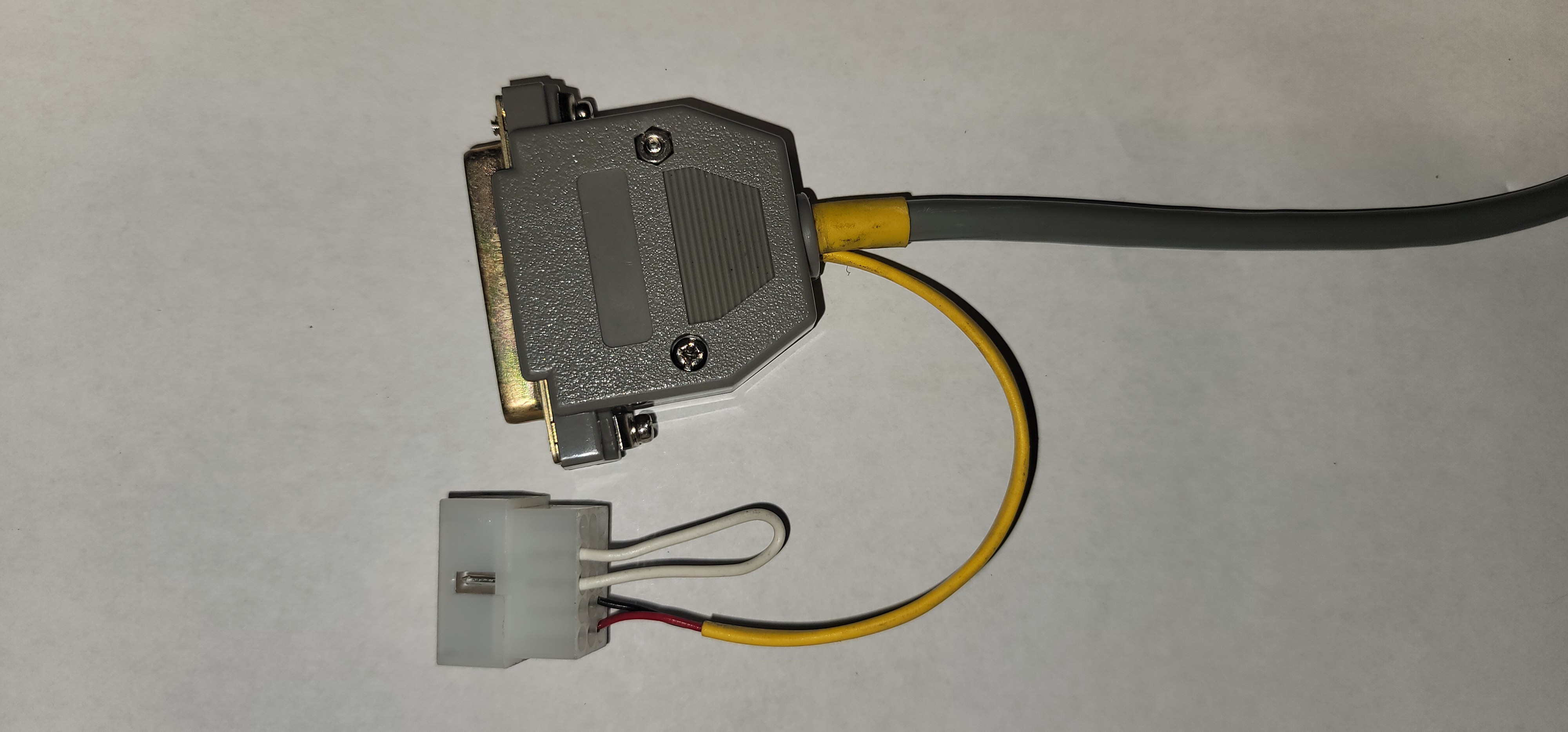
This article covers the connections between an external repeater controller and the Kenwood TKR-x50, TKR-x51 and NXR-x10. All six repeaters have similar packaging that includes a single DB-25 female connector and a single 15 pin "Molex" connector on the back of the chassis. Kenwood calls both of them "Accessory" connectors. Note that you won't have a front panel speaker unles you have a jumper between pins 9 and 12 in the Molex plug. And since the Molex plug is required you might as well add a pair of wires to power your external controller. (the red-black pair inside the yellow sleeving just loops through the DB-25 shell and feeds a pair in the grey cable to power the external controller)
Kenwood has a tech note that shows how to short out the power switch on the TKR-x50 and TKR-x51 units. Once this modification is done an accidentally bumped switch will not shut off a repeater. It's likely that the same tech note applies to the NXR-x10 units, however I have not needed to research if this is true. The shop where I help out a couple of days a week maintains about 40 TKR-x50s but only 4 NXR-x10s. Yes, I've bumped a switch, fortunately I caught it before I left the site. No, I've not tried out the mod.
Look for a setting labeled "DUPLEX" or "REPEAT" in the KPG-66, KPG-92 or KPG-129D programming software. When set to Repeat mode the the internal control and audio paths are enabled; Duplex mode completely separates the receiver and transmitter by disabling the internal controller. Once the repeater is programmed for "Duplex" service the DB-25 connector can be used to connect to an external repeater controller.
The DB-25 connector and the basic signals: The first four columns in the table are copied from the Kenwood data sheet.
Note: As far as the author can tell the only difference between a TKR interfacing cable and an NXR interfacing cable is that pins 14 and 18 are unused on a TKR and are diagnostic outputs on an NXR.
| Accessory 25 pin Female D-sub Connector, TKR-750 / TKR-850 | ||||
|---|---|---|---|---|
| DB-25 Pin | Signal Name | In or Out | Description / Function | Interfacing Notes |
| 1 | NC | – | No connection | The TKR-750 / 751 or TKR-850 / 851 can be modified to bring out RSSI on this pin. See page 13 here. I do not know if there is a similar modification for the NXR-710 or NXR-810. |
| 2 | RXD2 | I | Serial data to radio | You can program the NXRs with RS-232 signals on 2, 3 and 7. No, I do not know if you can program a TKR-x50 / x51 the same way. |
| 3 | TXD2 | O | Serial data from radio | |
| 4 | AI1 | I | Programmable function input 1 | No connection |
| 5 | AI2 | I | Programmable function input 2 | No connection |
| 6 | AI3 | I | Programmable function input 3 | No connection |
| 7 | DG | – | Control line ground | Ground |
| 8 | TD | I | TX data input (data or signalling) Input impedance: 600Ω Coupling: AC coupling Level: 0.5Vp-p input 100Hz Deviation: ±0.75kHz (wide) / ±0.35kHz (Narrow) |
This is the input that you should use for external PL or DPL encoders, or digital modulation. This input is not pre-emphasized. |
| 9 | TA | I | TX audio input (voice) Input impedance: 600Ω Coupling: AC coupling Frequency response: Pre-emphasis curve Deviation: 60% deviation (1kHz 280mVrms ±25mV input) |
This input is pre-emphasized and is where you would connect the repeat audio. |
| 10 | RD | O | RX data output (voice & data) Output impedance: 1kΩ or less Coupling: AC coupling Non-squelched Frequency response: ±2.5dB at 10~3000Hz Output level: 70~90mVrms (standard modulation) |
This output feeds external PL, DPL or digital modulation decoders, it is not de-emphasized. Think of this pin as raw receiver audio. |
| 11 | RA | O | RX audio output (voice) Output impedance: 1kΩ or less Coupling: AC coupling Squelched Frequency response: De-emphasis curve Output level: 360~440mVrms (standard modulation) |
This output is the repeat audio output and it to one to use to feed an external repeater controller. This output is de-emphasized. |
| 12 | RXG | – | RX signal ground (for RA and RD) | Receiver Audio Ground |
| 13 | SPM | I | Speaker mute signal. Muted when this input is low or grounded. | In most cases this pin can be ignored. |
| 14 | NC | - | No connection (see note) | No connection on the TKR units. The NXRs use this as "BER_CLK, Output, for Bit Error Rate Clock" |
| 15 | EMON | I | External monitor switch Input “low”= Monitor on, “high”= Monitor off. |
In most cases this pin can be ignored. |
| 16 | EPTT | I | External press-to-talk switch input | Active Low |
| 17 | SC | O | Squelch control output “L”: Busy, “H”: Not busy | This is a Receiver Unsquelched logic level output. |
| 18 | NC | - | No connection (see note) | No connection on TKR, on the NXR this is "BER_DAT Output for Bit Error Rate Data" |
| 19 | TXG | - | TX signal ground (for TA,TD) | Transmitter Audio Ground |
| 20 | AIO1 | I/O | Programmable function input or output #1 | No connection |
| 21 | AIO2 | I/O | Programmable function input or output #2 | No connection |
| 22 | AIO3 | I/O | Programmable function input or output #3 | No connection |
| 23 | AIO4 | I/O | Programmable function input or output #4 | On Version 2 TKRs and NXR-710s and NXR-810s this can be used for QT/DQT (CTCSS/DCS) encoder control. |
| 24 | AIO5 | I/O | Programmable function input or output #5 | Can be used for receiver TOR (CTCSS/DCS). |
| 25 | AIO6 | I/O | Programmable function input or output #6 | Can be used for receiver COR (COS). |
The 15-pin "Molex" connector:
The 15 pin Molex connector is not required to place the TKR-x50 / x51 or NXR-x10 units into service but it is a good thing to have a plug in the connector with a jumper between pins 9 and 12 as that jumper enables the front panel speaker. The connector can also provide +12 volts DC to power the external controller. If your controller has an extra A-to-D input you can feed the Received Signal Strength Indicator (RSSI) analog DC voltage on pin 8 and do remote signal strength measurements.
Yes, this is the same Molex connector as is used on the back of the TKR-x20 repeaters, however the pinout on those units is VERY different.
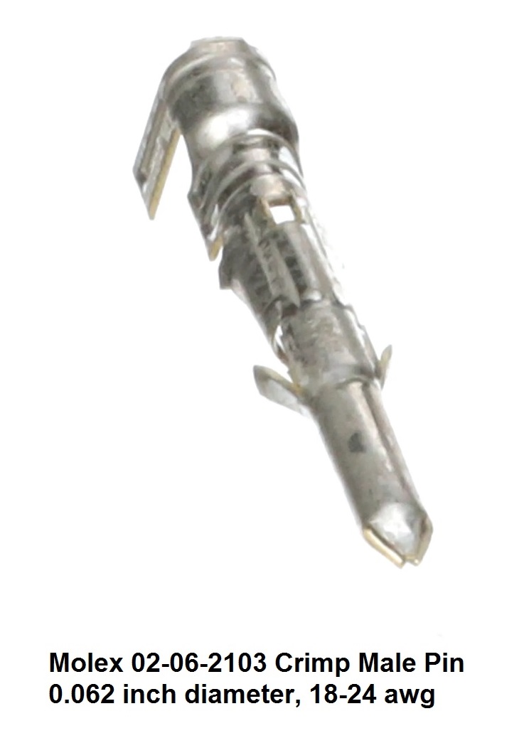
The 15 pin "Accessory" connector is one that was originally designed and made by "Molex" back in the 1970s. One part number was 03-06-2152 (body photo) (pin photo). That connector is a 5-row-by-3-column female body with 0.093 inch male pins. Today the parts are multiple-sourced, another manufacturer is TE Connectivity / AMP Connectors and they call it a Mini-Universal MATE-N-LOK Rectangular Power Connector #172171-1, 15 Position, 4.2 mm (0.165 inch) Centerline, UL 94V-0. AMP's data sheet (opens in a new window).
| 15-Pin Accessory Connector Info and Part Numbers | ||||||
|---|---|---|---|---|---|---|
| Molex Part Numbers | Distributor Part Numbers | |||||
| Old | Current | TE-AMP | Kenwood | Digikey | Mouser | |
| Housing: | 03-06-2152 (photo) (drawing) | 39033154 (PDF data sheet) | 172171-1 | ? | 900-0039033155-ND | 538-39-03-3155 |
| Pins: | 02-06-2103 (photo) (drawing) | 02062103 (PDF data sheet) | ? | ? | WM1000-ND | 538-02-06-2103 |
| Pin Crimp Tool: | 0638111000 | ? | WM9999-ND | 538-63811-1000 | ||
| Pin Extractor: | 0011030002 | ? | WM9929-ND | |||
| Pin Inserter: | 0011020001 | ? | WM5515-ND | |||
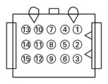
The easiest way to figure out which is pin 1 on the back of the TKR or NXR is to look for the triangular notches on one end, that's pins 1-2-3. The connect the black lead of your voltmeter to the chassis... the corner pin with +12 on it is pin 1 (note that the repeater power will need to be on).
The table below lists all 15 pins and what each one does. The first four columns in the table are copied from the Kenwood TKR data sheet. NXR differences are noted.
| Accessory "Molex"15-pin Connector Plug For Kenwood TKR740 / TKR840, TKR750 / TKR850 and NXR710 / NXR810 | ||||
|---|---|---|---|---|
| Pin # | Signal Name | In or Out | Description / Function | Notes |
| 1 | SB | O | Power supply output after power switch; 1 amp maximum | Either pin or both could power your external repeater controller (pair with pins 4 or 5 or both). |
| 2 | SB | O | Power supply output after power switch; 1 amp maximum | |
| 3 | NC | – | No connection | |
| 4 | GND | – | Ground | On the TKR pins 4 and 5 are "Ground", on the NXR they are "Digital Ground". See the note on pin 1. |
| 5 | GND | – | Ground | |
| 6 | SPG | – | Speaker ground | |
| 7 | RD | O | RX data output | Same as DB-25 connector pin 10. |
| 8 | RSSI | O | RSSI output (Analog signal output) | Connect to controller analog input for signal strength readout |
| 9 | SPI | I | Internal speaker input | Jumper to pin 12 to enable front panel speaker |
| 10 | AO1 | O | Auxiliary output 1 Open collector. Low : 150mA max. | |
| 11 | AO2 | O | Auxiliary output 2 Open collector. Low : 150mA max. | |
| 12 | SPO | O | External speaker output | Jumper to pin 9 to enable front panel speaker |
| 13 | AO3 | O | Auxiliary output 3 | |
| 14 | AO4 | O | Auxiliary output 4 | |
| 15 | AO5 | O | Auxiliary output 5 | |
Acknowledgements and Credits:
Ken Arck AH6LE at Arcom provided some of this info.
Back to the top of the page
Up one level (Kenwood Repeater Index)
Up two levels (Kenwood Index)
Back to Home
This page originally posted on 2023-Oct-10
Hand-coded HTML, photos and article text © Copyright 2023 by Mike Morris WA6ILQ. All Rights Reserved, including that of paper and web publication elsewhere.
This web page, this web site, the information presented in and on its pages and in these modifications and conversions is © Copyrighted 1995 and (date of last update) by Kevin Custer W3KKC and multiple originating authors.