Motorola index
Back to Home
Motorola DeskTrac
By Robert W. Meister WA1MIK

|
MaxTrac index Motorola index Back to Home |
An Overview of the Motorola DeskTrac By Robert W. Meister WA1MIK |
|
General Description:
The DeskTrac is a desktop station that contains one or two MaxTrac radios, a power supply, a front panel, and an optional remote control / line interface. These are available as base/control stations or repeater stations. Two separate antennas or an external duplexer is needed for the repeaters. A DeskTrac station can be configured to operate on the same bands as a MaxTrac radio and the duty cycle is 20% (1 minute transmit, 4 minutes receive), but they can optionally have an extended duty cycle of 60% (3 minutes transmit, 2 minutes receive) or a continuous duty cycle at 4 watts output. VHF-hi and UHF band repeaters have an extended duty cycle of 60% (3 minutes transmit, 2 minutes receive). The 800 MHz repeaters are continuous duty.
The DeskTrac stations have a longer duty cycle than their mobile radios would normally be capable of, mainly because of the forced-air cooling. The DeskTrac RSS knows about this issue and compensates for it, allowing longer transmit time and a higher duty cycle.
You can only have one channel or mode on a DeskTrac Repeater. The DeskTrac RSS will allow up to 16 channels or modes on a Base or Control station. Since Privacy-Plus stations are trunking, the DeskTrac RSS will let you view, but not change, the various channel or mode information. You'll have to use MaxTrac trunking RSS to change any of these parameters.
The service manual makes no mention of a DeskTrac based on a Spectra radio. All indications are that these only came with one or two MaxTrac radios inside. A list of model numbers provided with the programming software has the MaxTrac radio model numbers that would be found inside each station. The DeskTrac RSS manual also states that these stations are based on the MaxTrac mobile radios, and that MaxTrac RSS can be used to program the radios. The Spectra desktop station is built with the same cabinet and power supply and looks quite similar. If the 4th character of the model number is "S", then it's a MaxTrac-based DeskTrac station. If the 4th character is "K" or "Z", then it's got a Spectra radio inside and is a desktop station, NOT a DeskTrac. If there's a "T" at the end of the model number, then it's a repeater and should have two antenna jacks on the back and two radios inside it.
Several different remote control and audio sources can be connected to the DeskTrac. There is a priority table later in this article.
DeskTracs are produced in two versions: "A" and "B". The electronics are slightly different but the performance specifications are identical. The version is found in the 11th character of the model number. The following was received by the author from a person who actually worked on these radios at the factory:
The changes between A and B are in the logic board (the front board). The A had some "logical bugs" - it was designed using discreet logic (74xx) that was very difficult to fix without redesigning the circuit board for every issue or special request. So it was changed to a PAL 22V10 that was much easier to modify.
Cables from the DeskTrac front panel plug into the radio's control head connectors on the logic board as well as the 16-pin accessory jack at the back of the radio. This means that all radios in the DeskTrac must have 16-pin logic boards. The radios are also equipped with slightly different firmware than the stand-alone radio (see the table below).
| Application | Firmware |
|---|---|
| 900 MHz Privacy-Plus stations | FRN4007A |
| 800 MHz Repeater stations | FRN6531A |
| VHF/UHF Privacy-Plus stations | FVN5445A |
| All Base/Control stations | HLN5569A |
| VHF/UHF Repeater stations | HLN5569A |
| 800 MHz Privacy-Plus stations | HLN9435B |
Front Panel Controls:
The following photo was supplied by Scott KBØNLY. Click on the image for a larger view.
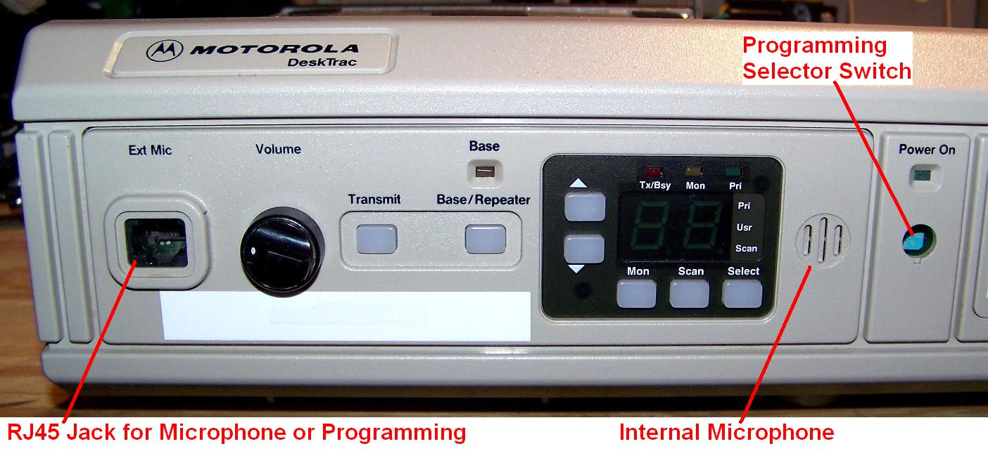
Left to right, there's the RJ45 jack, used for a microphone or programming the station. For some reason (perhaps because this product line and its documentation come from Israel), the pins are numbered 1-8, left to right, with the tab on the bottom. This numbering is completely backwards from the MaxTrac, GM300, and many other Motorola radios. The signals on this connector are in the same order; only the numbers are different. The table below documents the signals on the front panel Ext Mic jack:
| Pin | Signal Name |
|---|---|
| 1 | Headset Audio |
| 2 | Programming |
| 3 | PTT |
| 4 | MIC Audio |
| 5 | Ground |
| 6 | Monitor |
| 7 | H.D. (see note) |
| 8 | +5V |
This is followed by the Volume control for the loudspeakers. There's one speaker built into the front panel (not shown in this photo) to the right of the control panel area. This same audio is fed to any external speaker attached to the ACC3 accessory jack.
The Transmit button activates the transmitter and utilizes the local microphone further to the right.
The Base/Repeater button toggles between base station and repeater station operation. When repeater operation is enabled, the LED above this button will light up. This button has no effect on base/control or Privacy-Plus stations.
The black panel to the right is a standard MaxTrac mode selector panel. You can select modes to be scanned, activate scanning, select the current mode to transmit or receive, and disable coded squelch.
The local microphone is to the right of the MaxTrac control panel. This is only active when the front panel Transmit button is pressed.
The hole to the right normally has a beige cover plug in it. The blue object behind it is a rotary switch. This switch routes the programming data to the proper device inside the cabinet: the transceiver or transmitter in a repeater setup (the left radio, or radio #1), the receiver in a repeater setup (the right radio, or radio #2), or the remote control line interface that sits under the left radio. The Radio Service Software tells you where to set this switch during programming steps.
Above the programming selector switch is an LED that turns on when power is applied to the station. There is no power on/off switch; the station is always on when plugged in.
To the right of the control panel area is space for an optional clock / VU meter display board. The clock has hours and minutes and two buttons to set it. The VU meter has an LED bar graph that displays the received audio level. This is not shown in the photo above.
The following photos of an L37SUM5070B 900 MHz Privacy-Plus station were obtained from a popular auction web site (used without permission).
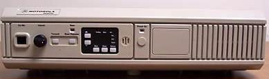
This photo shows the full front view of the DeskTrac. The speaker grill area on the right is rather plain looking. The programming switch cover is in place.
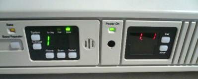
This photo shows the MaxTrac control panel as well as the optional clock / VU meter to its right.
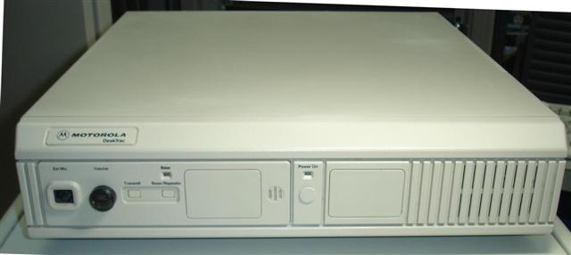
While most DeskTracs were meant to operate on a desktop, some could be put away in a closet and remotely controlled; as such there was no need for a control panel. Here's a photo of one (obtained from the web, used without permission, of course).
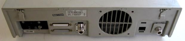
Here's a view of the rear of one station. From left to right: the AC power input jack (black area), the DB25F ACC3 (top) and ACC2 (bottom) accessory jacks, the N-female RX antenna jack, the fan, the RJ45 ACC3 accessory jack, and the N-female TX antenna jack.
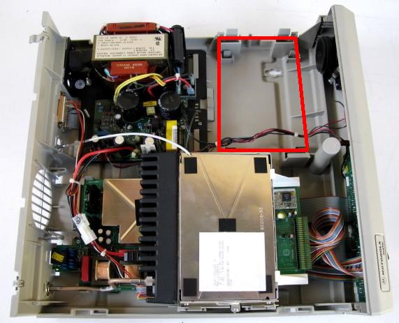
Here's an inside view of the station. The front of the station is at the right side of the photo. Starting at the upper left corner and moving clockwise, we have: the AC power supply, the blank area for a receiver (in a repeater station), outlined in red, the black loudspeaker on the back of the front panel, the control panel (with all the colored flat cables going to it), the HearClear board (plugged into the front of the radio), the MaxTrac radio with its heat-sink at the left (the RF board shield is facing the camera). Under the radio (in the lower left corner) you can see the DC/Tone remote control board (two transformers are visible, as well as a shield over the microprocessor).
The receiver radio, in a repeater station, consists of the chassis, RF board, and logic board. It takes up less space because there's no PA module attached to the rear. The radio receives DC power through the logic board's front panel connector.
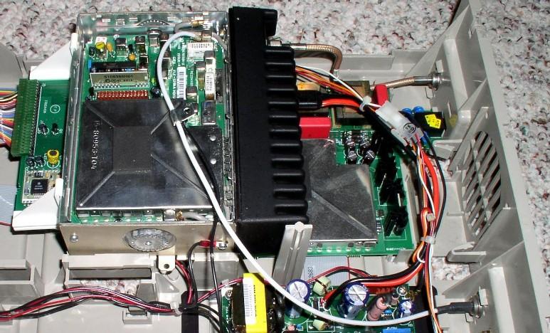
It's interesting that this Privacy-Plus station has two antenna jacks even though there's only one radio. The RX cable goes into a hole in the RF board shield at the upper left corner of the radio, and plugs into the receiver input jack on the RF board. I'm not sure why a half-duplex Privacy-Plus radio would need a separate antenna jack. That RX cable is supposed to plug into the RX jack of the receiver radio that's not present in this station. The cable clamp mounts to the rear of the RX chassis. Here's a photo, courtesy of Mark N9WYS, showing that cable under the shield of the MaxTrac:
Models and Specifications:
The various models and specifications are shown in the table below, sorted by model number. The Version letter (A or B) replaces the lower-case 'x'.
| Model Number | Pwr | Freq. Band | Station Type | Versn. |
|---|---|---|---|---|
| L24SUM7000xT | 2 | 403-470 MHz | Repeater | A or B |
| L24SUM70D0x | 2 | 403-470 MHz | Base/Control | A or B |
| L35SUM5070B | 12 | 806-870 MHz | Privacy-Plus | B only |
| L35SUM7000xT | 10 | 806-870 MHz | Repeater | B only |
| L35SUM70D0x | 15 | 806-870 MHz | Base/Control | A or B |
| L37SUM5070B | 12 | 896-941 MHz | Privacy-Plus | B only |
| L43SUM5070B | 25 | 136-174 MHz | Privacy-Plus | B only |
| L43SUM5170B | 25 | 136-174 MHz | Privacy-Plus | B only |
| L43SUM7000xT | 25 | 136-174 MHz | Repeater | A or B |
| L43SUM70D0x | 25 | 136-174 MHz | Base/Control | A or B |
| L43SUM71D0B | 25 | 136-174 MHz | Base/Control | B only |
| L44SUM5070B | 25 | 403-470 MHz | Privacy-Plus | B only |
| L44SUM7000xT | 25 | 403-470 MHz | Repeater | A or B |
| L44SUM70D0x | 25 | 403-470 MHz | Base/Control | A or B |
| L45SUM70D0x | 35 | 806-870 MHz | Base/Control | A or B |
| L51SUM70D0x | 45 | 29.7-50 MHz | Base/Control | A or B |
| L53SUM5070B | 45 | 136-174 MHz | Privacy-Plus | B only |
| L53SUM70D0x | 45 | 136-174 MHz | Base/Control | A or B |
| L54SUM5070B | 40 | 403-470 MHz | Privacy-Plus | B only |
| L54SUM70D0x | 40 | 403-470 MHz | Base/Control | A or B |
NOTES:
[1]: Stations with '1' in the 8th character of the model number are narrow-band and may
be programmed on 12.5 kHz increments. All others are wide-band, 25 kHz spacing.
[2]: Privacy-Plus and 12.5 kHz VHF stations are only available with Version B.
Base/Control or Repeater stations could be Version A or Version B. Version B is newer.
Some options will only work with Version B stations.
Frequency Bands and Ranges:
The Frequency Band is composed of several individual ranges that cover portions of the band, as shown in the table below. The programming software enforces these band limits.
| Band | Operating Ranges MHz | ||
|---|---|---|---|
| 29.7-50 | 29.7-36 | 36-42 | 42-50 |
| 136-174 | 136-162 | 146-174 | |
| 403-470 | 403-430 | 449-470 | |
| 800 MHz | 806-871 | ||
| 900 MHz | 896-941 | ||
Model Number String Breakdown:
The following table shows the breakdown of the model number characters. Only certain power level and band combinations are available; see the list above. In these tables, P-P stands for Privacy-Plus and B/R stands for Base or Repeater.
First six characters:
| Cabinet | Power | Band | Radio Series |
|---|---|---|---|
| L: always | 2: 1-5 | 1: VHF-lo | SUM: always |
| 3: 6-15 | 3: VHF-hi | ||
| 4: 16-35 | 4: UHF | ||
| 5: 36-45 | 5: 800 MHz | ||
| 7: 900 MHz |
Second six characters:
| Type | Chn. Spcg. | Sub-Type | Version | Repeater |
|---|---|---|---|---|
| 5: P-P | 0: 25 kHz | 00: Rptr | A: A | blank: base |
| 7: B/R | 1: 12.5 kHz | 70: P-P | B: B | T: repeater |
| D0: Base |
Available Options:
The following table lists the available options for the base/control, repeater, and Privacy-Plus configurations. Note that not all options are available for all station models.
| Option | Description | B/C | Rptr | P-P |
|---|---|---|---|---|
| L28 | Battery Revert/Charger | Y | Y | Y |
| L32 | 12VDC Only Operation | Y | Y | Y |
| L74 | Omit Duplexer | Y | ||
| L109 | Handset | Y | Y | Y |
| L110 | Boom Microphone | Y | Y | Y |
| L113 | Desk Microphone | Y | Y | Y |
| L114 | Clock and VU Meter | Y | Y | Y |
| L139 | DC Remote Control | Y | Y | Y |
| L141 | Local conversation Kit | Y | ||
| L146 | Tone Remote Control | Y | Y | Y |
| L273 | Space Saver | Y | Y | Y |
| L440 | Omit Conventional | Y | ||
| L570 | Headset | Y | Y | Y |
| L572 | Footswitch with PTT and Monitor | Y | Y | Y |
| L791 | Digital Remote Control | Y | Y | |
| L963 | Extended Duty | Y | Y | |
| L977 | Swan Neck Microphone | Y | Y | Y |
| L978 | Dispatching Adapter | Y | Y | Y |
Programming:
The DeskTrac base/repeater stations use DeskTrac Radio Service Software (RSS) package RVN-4079, which consists of the DeskTrac program and the conventional MaxTrac RSS package. The DeskTrac Privacy-Plus stations use DeskTrac RSS package RVN-4093, which consists of the same DeskTrac program and the trunking MaxTrac RSS package. The MaxTrac radios use MaxTrac Trunking RSS: RVN-4043/RVN-4044 or MaxTrac Conventional RSS: RVN-4019/RVN-4020; the appropriate MaxTrac package comes with the DeskTrac RSS package. A standard RIB and MaxTrac programming cable complete the setup. All of this is old DOS-only software; by now all readers should know what that implies. If not, see the RIB and RSS article elsewhere in the Motorola section on this web site.
Programming is done via the front panel MIC jack. A rotary switch in the middle of the DeskTrac's front housing controls whether RSS talks to the transceiver (or transmitter in repeater stations) in position 1 (fully counter-clockwise), or receiver (in repeater stations) in position 2, or the line interface in position 3 (fully clockwise). Pop the small round cover off the front and insert a flat-blade screwdriver into the switch to select the device you wish to program. The DeskTrac RSS tells you where to set this switch whenever you read or write a code plug to the station.
Besides the obvious radio mode fields (frequencies, coded squelch, etc), the RSS also sets the tone control function signals, DC control current values, and remote control operation. You can even program the displayed mode numbers to values between 01 and 99. Transmit time-out is also configured by the RSS. I didn't see anything in the HELP file or the RSS screens regarding CW ID, so there must not be one built-in.
The DeskTrac RSS program knows how to read and write some information in the MaxTrac radios. The following note is prominently displayed on page 1 of the RSS User Manual:
IMPORTANT NOTE
The last programming software that programs the DeskTrac repeater, base or control station should always be DeskTrac RSS.
DeskTrac RSS overwrites some parameters that are written by the MaxTrac RSS. The parameters that are written by the MaxTrac RSS can cause improper DeskTrac operation. Remember: After using MaxTrac mobile RSS you should at least read the code plug of the DeskTrac unit with DeskTrac RSS and then write it back to the DeskTrac again (program DeskTrac) using DeskTrac RSS.
Another page states:
This radio service software package is intended to modify the parameters of the DeskTrac. It is intended to be used together with standard MaxTrac mobile RSS. In most cases the use of DeskTrac service software alone is sufficient to program the DeskTrac. In some cases where extended features from the DeskTrac are required, like: signalling or addition/deletion of modes, the MaxTrac mobile RSS is required. For further information on using MaxTrac mobile RSS refer to its manual.
Part of this issue is explained by the following, which was received by the author from a person who actually designed the DeskTrac:
One of the reasons that you need to end your programming session with the DeskTrac RSS is that it changes the thermal parameters when you do so. The original Maxtrac is designed as a mobile radio with limited duty cycle to be cooled by convection air flow and in the DeskTrac a fan was added for forced air cooling, thus it cools better and allows longer duty cycles (the actual temperature measurement is far away from the power amplifier module and the temperature at the power transistors is estimated mainly on the transmit duration).
Front Panel Jumper Settings:
JU1 sets the repeater drop-out delay or hang-time. 0 seconds: position 2-3; 1 second: position 1-2; 2 seconds: no jumper.
JU2 on version "A" stations controls monitoring operation. It is set to position 1-2 for the internal microphone and position 2-3 for an external microphone with an external monitor pedal.
JU2 on version "B" stations is removed for external microphone operation.
JU3 on version "B" stations is removed for extended local desk set operation.
Accessory Jack Signals:
All of these connectors are located on the rear of the DeskTrac station.
The ACC1 jack (RJ45) is used to connect a DC/Tone remote console. The tab is on the bottom and the pins are numbered left to right: 1 through 8.
| Pin | Signal Name | Used For |
|---|---|---|
| 1 | LINE1 DC+ | 2-4 Wire TX |
| 2 | LINE2 DC- | 2/4 Wire TX |
| 3 | LINE 3 | 4-wire RX |
| 4 | LINE 4 | 4-wire RX |
| 5 | BUSY | |
| 6 | BUSY GND | |
| 7 | DATA+ | |
| 8 | DATA- |
The Line Control Board has jumpers on it to select 2- or 4-wire operation. There are two board versions: A and B. Make sure you use the information appropriate for the board in your station. The relevant page from the service manual has been scanned and can be found here as a 55kb PDF file.
The ACC2 jack (DB25-F) is used to connect several optional devices.
Certain pins are only assigned for specific applications. See the notes in the description and at the end of the table.
| Pin | Signal Name | Dir | Description and Specifications |
|---|---|---|---|
| 1 | GND | Ground. | |
| 2 | N.C. | Not connected. | |
| 3 | B+ | OUT | Provides 13.8 VDC at 750 mA. |
| 4 | PCC TEL | IN | Active low level keys the transmitter with audio from pin 5. |
| 5 | MIC TEL | IN | Transmit pre-emphasis audio input, provides 3 kHz deviation to 1 kHz tone at 150 mV rms. |
| 6 | GND | Ground. | |
| 7 | DRXA TEL | OUT | Filtered and de-emphasized received audio output, provides 600 mV rms to a received 1 kHz tone at 3 kHz deviation. |
| 8 | GND | Ground. | |
| 9 | CHAN MON | OUT | Carrier squelch indicator output, active low. |
| 10 | B+ | OUT | Provides 13.8 VDC at 750 mA. |
| 11 | EXT ALARM | OUT | Active high output for 6 sec when Call Alert page, Private Conversation, and Telephone Interconnect calls are received (programmed I/O). See Note 1. |
| 12 | PL CH MON | OUT | Code squelch (PL and DPL) indicator output, active low. See Note 2. |
| 13 | PTT | IN | Active low level keys the transmitter with flat transmit audio from combined inputs of pin 22 and 17. |
| 14 | LINE PTT | OUT | PTT from output of Line Control board (if used), indicating line activated PTT (active low). |
| 15 | DRXA EXT LCL | OUT | Filtered and de-emphasized received audio output, provides 1V rms to a received 1 kHz tone at 3 kHz deviation. |
| 16 | TXA EXT LCL | IN | Transmit pre-emphasized audio input, provides 3 kHz deviation to an input of a 1 kHz tone at 500 mV rms. |
| 17 | TX CTCSS | IN | Transmit CTCSS input, provides 3 kHz deviation to an input of a 1 kHz tone at 330 mV rms. |
| 18 | MONITOR | IN | Monitors momentary input to unsquelch receiver. |
| 19 | PTT EXT LCL | IN | Active low level keys the transmitter with audio from pin 16. |
| 20 | RPTR DIS | IN | Active low disables internal repeater operation. Must be active prior to repeating operation. See Note 2. |
| 21 | TX PL INH | IN | Transmit PL and DPL inhibit input, active low. See Note 2. |
| 22 | TXA | IN | Transmit flat audio input, provides 3 kHz deviation to an input of a 1 kHz tone at 330 mV rms. |
| 23 | RXA | OUT | Received (flat discriminator) audio output, provides 330 mV rms to a received 1 kHz tone at 3 kHz deviation. |
| 24 | PTT PAGER | IN | Active low keys the transmitter with audio from pin 25. |
| 25 | MIC PAGER | IN | Transmit pre-emphasized audio input, provides 3 kHz deviation to a 1 kHz tone at 120 mV rms. |
NOTES:
[1]: Not applicable on repeater stations.
[2]: Not active on Privacy-Plus stations.
The ACC3 jack (DB25-F) is used for an external loudspeaker and an Emergency Switch.
| Pin | Signal Name and/or Function |
|---|---|
| 11+24 | Speaker Audio High Output |
| 18+19 | Speaker Audio Low Output |
| 9 | Emergency Switch Input (to pin 19) |
Device Connection Matrix:
Input devices utilize specific pins in the ACC2 jack. An explanation of the signal names can be found in the ACC2 table above. For Privacy-Plus stations, the Extended Local Desk Set is the only attachable device. The following list shows the pin usage by device. The column names are abbreviated as follows:
| Pin | Signal Name | PE | TI | EL | CR | BSC |
|---|---|---|---|---|---|---|
| 1 | GND | Y | Y | Y | Y | Y |
| 2 | N.C. | |||||
| 3 | B+ | Y | ||||
| 4 | PTT TEL | Y | ||||
| 5 | MIC TEL | Y | ||||
| 6 | GND | Y | ||||
| 7 | DRXA TEL | Y | ||||
| 8 | GND | Y | ||||
| 9 | CH. MON. | Y | Y | Y | Y | |
| 10 | B+ | Y | Y | Y | Y | |
| 11 | N.A. | |||||
| 12 | PL CH. MON. | Y | ||||
| 13 | PTT | Y | ||||
| 14 | LINE PTT | Y | ||||
| 15 | DRXA EXT LCL | Y | ||||
| 16 | TXA EXT LCL | Y | ||||
| 17 | TX CTCSS | Y | ||||
| 18 | MONITOR | Y | ||||
| 19 | PTT EXT LCL | Y | ||||
| 20 | RPTR. DIS. | Y | Y | |||
| 21 | TX PL INH. | Y | ||||
| 22 | TXA | Y | ||||
| 23 | RXA | Y | Y | |||
| 24 | PTT PAGER | Y | ||||
| 25 | MIC PAGER | Y |
Audio Input Priority:
The transmitter can be operated by various input devices. The table below defines which input will be selected when more than one input attempts to become active. The audio source with the highest priority will key and modulate the transmitter.
| Priority | Functional Input | Connector Description |
|---|---|---|
| 1 | Front Panel Microphone | Internal |
| 2 | External Microphone | Front panel "Ext Mic" jack (RJ45) |
| 3 | Remote Desk Set | ACC1 jack (RJ45) |
| 4 | Extended Local Desk Set | ACC2 pin 16 |
| 5 | Repeater Receiver Audio | Internal, Repeater Stations Only |
| 6 | Telephone Interconnect | ACC2 pin 5 |
| 7 | Flat Audio | ACC2 pins 17 and 22 |
| 8 | Paging Encoder | ACC2 pin 25 |
Interfacing Information:
The primary method of connecting external equipment is through the Accessory jacks. All internal radio connection points (the control head connector on the logic board and the 16-pin accessory jack at the back of the radio) are occupied by flat cables feeding the front panel circuit board. You'd have to intercept the desired signals by building a special cable or cutting into the stock cables.
The MaxTrac RSS programs the 16-pin accessory jack with dedicated functions on specific pins. While you can certainly change these functions or pin assignments, doing so may interfere with regular station operation.
In the following tables, "N/C" means Not Connected.
The MaxTrac 16-pin accessory jack provides the following signals to the front panel J6 connector unless otherwise noted. The pin numbers are the same for the radio and front panel ends of the cable. These signals come from the single transceiver (in base/control stations) or the transmitter (in repeater stations).
| Pin | MaxTrac Signal Name | DeskTrac Signal Name |
|---|---|---|
| 1 | Speaker Low Out | Goes to ACC3 |
| 2 | MIC Audio In | N/C |
| 3 | MIC PTT In | N/C |
| 4 | Programmed I /O | Channel Monitor |
| 5 | Flat TX Audio In | TXA |
| 6 | Programmed I /O | PAGE-PTT |
| 7 | Ground | N/C |
| 8 | Programmed I /O | N/C |
| 9 | Emergency Switch In | S.B. (see note) |
| 10 | Ignition Control In | N/C |
| 11 | Flat RX Audio Out | RXA |
| 12 | Programmed I /O | TX PL Inhibit |
| 13 | Switched A+ | N/C |
| 14 | Programmed I /O | PL and Channel Monitor |
| 15 | Internal Speaker In | Goes to ACC3 |
| 16 | Speaker High Out | Goes to ACC3 |
The MaxTrac logic board connector normally feeds the radio's control head. It has two sections: one (J8) handles the channel display and push buttons and goes directly to the front panel electronics. There are no interfacing signals available on that section. The other section (J9) feeds the VOL/MIC circuit board in the MaxTrac control head. There are some useful signals here. Everything comes into the front panel board via J4.
| J8 Pin | J9 Pin | J4 Pin | DeskTrac Signal Name |
|---|---|---|---|
| 1 | --- | 1 | Volume Control Top |
| 2 | --- | 2 | Volume Control Wiper |
| 3 | --- | 3 | N/C |
| 4 | --- | 4 | N/C |
| 5 | --- | 5 | Switched B+ |
| 6 | --- | 6 | B+ |
| 7 | --- | 7 | Programming Line |
| 8 | --- | 8 | See Note 1 |
| 9 | --- | 9 | See Note 2 |
| 10 | --- | 10 | Ground |
| 11 | --- | 11 | PTT |
| 12 | --- | 12 | MIC Audio |
| 13 | --- | 13 | Hook/Monitor |
| --- | 1 | 14 | TX/BSY LED |
| --- | 2 | 15 | Display Enable |
| --- | 3 | 16 | FPD (Scan) |
| --- | 4 | 17 | FPE (Select) |
| --- | 5 | 18 | FPB (Down) |
| --- | 6 | 19 | FPC (Mon) |
| --- | 7 | 20 | FPA (Up) |
| --- | 8 | 21 | N/C |
| --- | 9 | 22 | +5V |
| --- | 10 | 23 | Serial Data |
| --- | 11 | 24 | Serial Clock |
| --- | 12 | 25 | Ground |
| --- | --- | 26 | N/C |
The front panel J7 connector provides the following signals to the ACC2 connector. In this table, suffixes to signal names indicate the external device that would utilize them. See the "Device Connection Matrix" table above for more details. "CR" means Community Repeater, "PAG" means Pager, "TEL" means Telephone Interface, "EXT-LCL" means External or Local Remote Control.
| J7 Pin | ACC2 Pin | DeskTrac Signal Name |
|---|---|---|
| 1 | 13 | PTT-CR |
| 2 | 25 | MIC-PAG |
| 3 | 12 | PL and Channel Monitor-TEL |
| 4 | 24 | PTT-PAG |
| 5 | 11 | N/C |
| 6 | 23 | RXA |
| 7 | 10 | B+ |
| 8 | 22 | TXA-CR |
| 9 | 9 | Channel Monitor |
| 10 | 21 | TX PL Inhibit |
| 11 | 8 | Ground |
| 12 | 20 | Repeater Disable |
| 13 | 7 | DRXA-TEL |
| 14 | 19 | PTT-EXT-LCL |
| 15 | 6 | Ground |
| 16 | 18 | MON-EXT-LCL |
| 17 | 5 | MIC-TEL |
| 18 | 17 | CTCSS-CR |
| 19 | 4 | PTT-TEL |
| 20 | 16 | TXA-EXT-LCL |
| 21 | 3 | B+ |
| 22 | 15 | DRXA-EXT-LCL |
| 23 | 2 | N/C |
| 24 | 14 | LINE PTT |
| 25 | 1 | Ground |
| 26 | --- | N/C |
Radio Accessory Jack Programming:
If you end up blanking a radio, or need to completely reprogram it, and never saved the original code plug, the following information may be of use: it's the accessory jack configuration screens from a stock 900 MHz Privacy-Plus radio (L37SUM5070A).
INTERNAL ACCESSORY: None  EXTERNAL ACCESSORY:   PUBLIC ADDRESS  CUSTOM:  No
   PIN #   FUNC. # and DESCRIPTION   DATA DIRECTION   DEBOUNCE   ACTIVE LEVEL
     4       3  External Alarm        Output           No          High
     6       0  NULL                   Input           No           Low
     8       0  NULL                   Input           No           Low
     9       0  NULL                   Input           No           Low
    12       0  NULL                   Input           No           Low
    14       4  PA Switch              Input          Yes           Low

INTERNAL ACCESSORY: None  EXTERNAL ACCESSORY:           REMOTE  CUSTOM:  No
   PIN #   FUNC. # and DESCRIPTION   DATA DIRECTION   DEBOUNCE   ACTIVE LEVEL
     4       3  External Alarm        Output           No          High
     6       0  NULL                   Input           No           Low
     8       0  NULL                   Input           No           Low
     9       0  NULL                   Input           No           Low
    12       0  NULL                   Input           No           Low
    14      10  I/O Mic Off Hook       Input          Yes           Low
The DeskTrac RSS User's Manual has this to say about the radio's configuration after board replacement:
Refer to the appropriate MaxTrac RSS and DeskTrac service manuals to replace the radio (unified chassis) board. After completion of alignment and calibration procedures, program the radio with the desired MaxTrac and DeskTrac archive files (previously saved). The archive file is necessary for trunked stations and conventional stations with extended duty cycle. For conventional DeskTrac stations (w/o extended duty option) it is possible to initialize a blank logic board with MaxTrac RSS. In that case the MaxTrac product line should be "Max High Sig"; Model name "MaxTrac 300"; Panel "001". It is mandatory to perform read/write procedure with the DeskTrac RSS after the MaxTrac RSS was used. If the radio accessory connector differs from the default values then perform default programming (<F8>) for "Moden Paging" configuration.
Miscellaneous Unrelated Information Tidbits:
HearClear is implemented only on the 896-941 MHz Privacy-Plus stations. They took the HearClear hybrid module from the MaxTrac volume control circuit board and mounted it on a new board that goes in series with one of the cables running between the transceiver and the front panel board. It can be enabled or disabled on a channel-by-channel basis, just like a regular MaxTrac.
The 806-870 MHz repeater has to receive in the 806-825 MHz range. None of the MaxTrac service manuals I have show an RF board with this capability, but one must exist. I have found out that a talk-around RF board, when fitted with different Murata front-end filters centered at 815 MHz (to pass the 806-825 MHz signal), is called an FLF5543A. The unique radio firmware and the DeskTrac RSS let you enter the lower receive frequency. No printed documentation has been found yet.
The stations can be purchased to operate on 120/240VAC or 14VDC. Battery backup is available on the AC-powered stations. A separate charger provides 100mA of trickle charge current.
The DeskTrac RSS User's Guide is p/n 6802982G55 and cost about $30US in May 2009.
The DeskTrac Service Manual contains sections for each station type: Base/Control, Repeater, and Privacy-Plus, that provide jumper, installation, and alignment information. There are also schematics for two versions of the front panel board, the DC/Tone remote board, the Digital Remote board, the clock/VU meter, and the power supply. Each of these are several foldout pages long and include color X-ray views.
Here are the wiring diagrams for the version "A" and "B" repeater stations.
Acknowledgements and Credits:
DeskTrac, MaxTrac, Radius, Privacy-Plus, Spectra, RSS, and a whole bunch of other terms are trademarks of Motorola, Inc.
Just about all of the information and specifications came from the DeskTrac Service Manual, 6802993G65, purchased in December 2008 for $77US, soon to be NLA.
Thanks to Scott Lichtsinn, KBØNLY, amateur photographer, for supplying the detailed photo of the front of his DeskTrac station.
Thanks to Mark Tomany, N9WYS, for supplying the detailed photo of the inside of the 900 MHz Privacy-Plus station, showing the receive antenna cable routing.
Contact Information:
The author can be contacted at: his-callsign [ at ] comcast [ dot ] net.
Back to the top of the page
Up one level (MaxTrac index)
Up two levels (Motorola index)
Back to Home
This page originally posted on Sunday 21-Dec-2008
Article text, artistic layout, and hand-coded HTML © Copyright 2008 by Robert W. Meister WA1MIK.
This web page, this web site, the information presented in and on its pages and in these modifications and conversions is © Copyrighted 1995 and (date of last update) by Kevin Custer W3KKC and multiple originating authors. All Rights Reserved, including that of paper and web publication elsewhere.