Back to Home
Originally Compiled and HTML'd by Mike Morris WA6ILQ
Formerly Maintained by Robert Meister WA1MIK (SK)
Currently Maintained by Mike Morris WA6ILQ

|
Up one level (Motorola main index) Back to Home |
The Motorola MaxTrac, Radius, GM300, DeskTrac and GR-series Repeaters Index Page Originally Compiled and HTML'd by Mike Morris WA6ILQ Formerly Maintained by Robert Meister WA1MIK (SK) Currently Maintained by Mike Morris WA6ILQ |
|
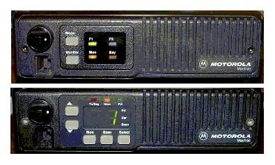
Maxtrac family radios have rectangular buttons,
GM300 family radios have round buttons.
Attention Ebay buyers and sellers: If you are buying or selling a MaxTrac, Radius mobile, or GM300 you need to read the warning on this page.
Any Motorola prices mentioned on this page (or on any page at this web site) should be taken only as a rough guideline. Motorola adjusts prices quarterly, and offers one set of prices to their dealers/service shops (the so called "NSO" Pricing ("National Service Organization")), another to "self-maintaining" fleet customers (i.e. those that have their own radio shops... cities, counties, police departments, fire departments, etc) and a third on their telephone order desk (i.e. retail sales to the public). Prices are changed quarterly, so use the mentioned prices only as a rough indication. If you encounter a large price change on anything where we've mentioned a price we'd appreciate an emailed update.
Radio Modification and Descriptive Articles:
Caution: A lot of the information in the articles below is valid only for MaxTracs and MaxTrac-based Radius radios (the Radius mobiles that have the letters LRA in the middle of the model number). The MaxTracs came first, then when Motorola needed radios to sell as Radius models (i.e. retail sales products) they changed the label and the firmware. There are some very slight differences, but there is a lot of commonality between the hardware (the circuit boards, etc) inside the MaxTrac and Radius LRA series mobiles.
The later GM300 series (which includes the Radius M10, M120 and M130 radios) look a lot like the MaxTrac and Radius LRA series, have similar specifications and physical construction, but are actually quite different internally. Think of the GM300 as the opportunity for Moto Engineering to fix all of the Maxtrac design oversights. For one, the GM300 series have a thermistor in the PA deck and therefore the transmitter "knows" if you put a fan on the PA deck...
The GM300 series do not respond well to being blanked by the MaxTrac Lab RSS. There is no Radius or GM300 series Lab RSS floating around (and probably never will be) so unsuspecting experimenters can turn one of these radios into an expensive brick if not careful. See the GM300 article below for more details.
Astron makes a power supply for the MaxTrac / Radius LRA / GM300 series that has a sleeve on the top that the radio slides into. The SL-11-RRA supplies 13.8V at 11 amps. Click here for a photo.
Note that the mid-power and high-power MaxTrac / Radius / GM300 radios have a 10% transmit duty cycle and that translates to 10 seconds of transmit and 90 seconds of receive, or 30 seconds of transmit and 4.5 minutes of receive. This is definitely not repeater service or any kind of amateur radio service that I'm familiar with! And besides, the rear mounted heat sink does not cool the pin diodes or any other PC-board mounted components. Reducing the transmit power can help, but some models have a minimum rated power level (for example, not less than 25 watts and not more than 45 watts) and going below that is not recommended - the transmitter is underdriven, gets squirrely, and the efficiency goes way down. In other words, the MaxTrac, Radius and GM300 are nowhere near the conservatively rated and over-heat-sinked designs of the MICOR, Syntor or Mitrek era radios.
 |
Introductory Information on
the MaxTrac, Radius and GM300 series radios, the DeskTrac station, and the GR300,
GR400, GR500, GR1225, R1225 and RKR1225 series repeaters
Compiled by Mike Morris WA6ILQ An introduction to the Motorola radios covered by this section, with background, history, some model-specific information, photos, and lots of miscellaneous tidbits such as mic jack or antenna connector replacement. You should read this article before any of the other articles here. |
|
An Introduction to the MaxTrac
or Radius M100 / M214 / M216 Firmware, Logic Boards and
RF Boards By Neil Johnson WBØEMU What your radio can do depends a lot on what version firmware you have in which logic board mated to which RF board. |
|
Identifying the
five most common Radius models By Bob DeMattia K1IW Some front panel images with text that describes the major differences. |
|
MaxTrac Logic Board
Jumpers and Connectors By Robert Meister WA1MIK Locations and explanations of the three-pin jumpers on MaxTrac and Radius logic boards, as well as the signals on the three multi-pin connectors. |
|
The Definitive Guide to the 16 pin
MaxTrac and Radius Option Connector By Neil Johnson WBØEMU Not every output pin or input pin is equal... Some are more equal than others... |
|
Transmitter Spurious Outputs when run
at less than rated power By Robert Meister WA1MIK The myth about running radios at less than rated output power: confirmed, plausible or busted? The author does some simple experiments and analysis. |
|
That annoying "cli-click"
when the PTT button is released By Robert Meister WA1MIK Some radios do it, some don't. The author traced the source and shows several ways to get rid of it. |
|
Microphone Hang-up
Mechanisms By Robert Meister WA1MIK A primer on hang-up buttons found on MaxTrac mikes, but the same schemes are used by a lot of other Motorola radios, and some similar schemes are even used on radios made by other manufacturers. |
|
Self-Quieting Frequencies
Compiled by Robert Meister WA1MIK GM300, MaxTrac, Radius, and MaraTrac mobile radios all share designs and components, so they all suffer from this problem. Here's a collection of frequencies that these radios can generate internally; some of them can be annoying. |
Model-Specific Articles:
|
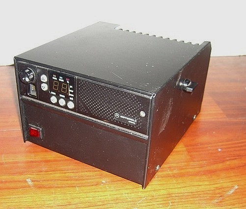
Overview of the DeskTrac Station
By Robert Meister WA1MIK Model numbers, connectors, interface signals, front panel overview, photographs. A lot of the information came from the DeskTrac Service Manual. |
|
Information about the GM300-series
radios By Robert Meister WA1MIK Specs, board numbers, accessory plugs, how they differ from MaxTracs. |
|
MaxTrac VHF, UHF, and 800
MHz radio models By the Repeater-Builder Staff Information taken directly from the "No Longer Available" detailed service manual. |
|
MaxTrac 900 MHz radio
models By Repeater-Builder Staff Information taken directly from the "No Longer Available" service manuals. |
|
Radius M100, M206, M208, M214, M216
radio models and board info Compiled by Robert W. Meister WA1MIK Information extracted from the Radius Service Manual (of course NLA). |
|
A reproduction of the MaxTrac Performance Specifications 20KB PDF file |
|
MaxTrac initialization programming
choices By Robert Meister WA1MIK A follow-up to the article below that details the once-only screen fields you must fill in when initializing a radio. |
 |
Hex-editing the 900 MHz MaxTrac MDF file by
Robert Meister WA1MIK This article describes the process that you have to do so you can easily program your MaxTrac on amateur 900 MHz frequencies. You can find it in the Motorola RSS and RIB articles section of this web site. |
|
MaxTrac Secrets
By Robert Meister WA1MIK Communications, code plug, and other internal data secrets of the MaxTrac-series radios. |
|
How the MaxTrac Controls Transmit
Power and Deviation By Robert Meister WA1MIK An explanation of why the radio has weird transmit power and deviation on amateur frequencies and what you can do about it. Applies to GM300, Radius, and MaraTrac radios too. |
|
Ham-friendly Firmware Mods for the
MaxTrac By Robert Meister WA1MIK What to change in the firmware to deal with out-of-band operation. A follow-up to the article above. Applies to Radius and MaraTrac radios too. |
|
How to replace the firmware and what to
align for the MaxTrac By Robert Meister WA1MIK The procedure to replace the firmware chip and what needs to be realigned when doing so. A follow-up to the article above. Applies to Radius and MaraTrac radios too. |
|
MaxTrac Adjustments
By Robert Meister WA1MIK More than you ever wanted to know about the various pots and coils on the RF boards of the MaxTrac-series radios, and how to adjust them. Of course Motorola doesn't want you to twiddle with these, but occasionally it's necessary. |
|
Replacing the Dallas Memory
Module In the MaxTrac or Radius By Scott Withrow KC9LQV Radios that use the Dallas NVRAM will be losing their memory when the battery goes dead. They have about a 20 year lifetime, so any radio made prior to about 1992 will have this problem and the Dallas chip will need to be replaced. This article tells you what to do about it. |
Some additional GM300 information is available from Colin Lowe G1IVG at http://www.g1ivg.com/motgm300.htm (offsite link).
Interfacing Articles:
|
Kurt Meltzer, KC4NX / WB9KNX / Meltzer Radio Engineering sells a wide variety of
both 5-pin and 16-pin connector / interfacing / cable kits on ebay as seller "mre1032" (Kurt Meltzer, KC4NX / WB9KNX, Meltzer Radio Engineering). (off-site pointer, opens in a new browser tab) The last time I looked there were over 2 dozen listings for 16-pin cables for a number of Motorola models that use the 16 pin connector. Full Disclosure: I have no relationship with Kurt other than as a very satisfied email-order customer and he's not paying me for this recommendation. I think Kurt's cable kits are wonderful and they have saved me a lot of frustration. He's been very receptive to customizing kits. I just have 70+ year old eyes and have big fat fingers that have difficulty crimping the accessory connector tiny pins onto the individual wires, and then getting the pins into the plastic body rightside up (needlenose pliers and a large illuminated magnifying glass are a big help). (off-site pointer, opens in a new browser tab) |
|
Repeater controller
interfacing - with photos By Scott Lichtsinn KBØNLY With information on connections to radios with both 5-pin and 16-pin logic boards. |
|
Simple Repeater Interfacing for
MaxTrac / Radius / GM300 Radios By Robert Meister WA1MIK A very simple procedure with all the details needed to interface these radios to most repeater controllers. This is a companion article to the ones above and below. |
|
Repeater Interface
for two radios 207 kB PDF Using a ID-O-Matic II kit, by Dale NØXAS, that has both a CW ID and a Time-Out/hang timer to make a repeater using MaxTrac, Radius, GM300, or CDM-series mobile radios. |
|
Packet / APRS connections
to the MaxTrac / Radius / GM300 series
radios by Earl Garber, N3EG Covers three different sets of connections: (1) to the front microphone jack, (2) in parallel with the front panel to logic board connector, and (3) the rear accessory jack. You can pick the one you want to use. |
|
Using a MaxTrac / Radius / GM300
Mobile Radio as a CW Beacon Transmitter By Robert Meister WA1MIK The HamGadgets ID-O-Matic had all the features necessary for this task. It was just a matter of finding a way to transmit real on/off CW rather than modulated audio CW for beacon use. Should also work with the MaraTrac radios. |
|
Using Remote Channel Select on
a 16-channel GM300 radio By Robert Meister WA1MIK A transcription of a PDF file with additional information that explains the wiring and radio configuration you need to remotely select channels on the 16-channel GM300 radio. This won't work on the 2-channel M120 or the 8-channel GM300 because the firmware won't allow you to reprogram the accessory connector pins for this purpose. |
Modification and Repair Articles:
|
Believe it or not, Amazon stocks the green-bodied 2 amp Pico Fuse that is inside the Maxtrac and GM300 series radios. At the time this paragraph was added (2023-DEC-10 by WA6ILQ) they are sold as a package of 5 for US$4.50 plus shipping... Look here: https://www.amazon.com/Littelfuse-251002-125V-AXIAL-acting/dp/B005DNQTG8. |
|
Diagnosing, Troubleshooting, and
Repairing MaxTrac Radios By Robert Meister WA1MIK Hints and helpful suggestions for repairing MaxTrac, Radius, and GM300 mobile radios. |
|
Disassembling the GM300 Mobile
Radios By Robert Meister WA1MIK If your GM300 is way off frequency, this is usually caused by dirty interconnect pins between the logic board and the RF board. You'll need to take it completely apart to clean them. Here's a procedure for doing it. |
|
Narrow-band conversion kits for the
GM300-series radios By Robert Meister WA1MIK Transcribed from the official document that can be found elsewhere on this site. |
|
Adding additional channels
to the GM300 By Thomas M. Mayse, KN5S If your GM300 has the expanded logic board it can have as many as 40 channels. Moto learned their lesson on the 32-channel MaxTrac and artificially limited GM300 to 16 channels so that they could force anyone needing more than 16 into a Spectra. Tom walks you through the process with a step-by-step procedure. |
|
Upgrading a MaxTrac or Radius
M100 / M214 / M216 to 32 channels - with
photos By Scott Lichtsinn KBØNLY A step-by-step procedure that will upgrade any MaxTrac (except the 2-channel ones) to 16 or 32 channels (depending on which logic board you have), with options like scan. |
|
Additional
Notes on MaxTrac or Radius M100 / M214 / M216 Logic
Boards By Scott Lichtsinn KBØNLY This article goes with the "Upgrading" article above. It has additional notes including a procedure for converting a trunking logic board to conventional. |
|
Moving a 449-470 MHz
MaxTrac to cover the 440-450 MHz Amateur band - with photos
By Scott Lichtsinn KBØNLY A step-by-step procedure that makes a UHF MaxTrac a lot more useful on 440-450 MHz. |
|
Manual Power
Control of the MaxTrac PA deck By Robert Meister WA1MIK When a MaxTrac (on any band) is run out of it's designed frequency range the power control routines in the firmware get confused. Unfortunately the confusion causes the radio to run the PA deck wide open, which can burn it up. This writeup gives a workaround. |
|
Volume Control
Replacement By Robert Meister WA1MIK If you have a MaxTrac, Radius LRA or GM300 series radio that runs at full volume all the time, or either turning the volume control has no effect or causes a huge jump in volume, then you have a broken volume control (a common problem). It's a simple, inexpensive fix and this writeup walks you through the repair. |
|
Volume Control
Replacement UPDATE By Robert Meister WA1MIK The original and new Motorola pots are No Longer Available but an alternate part can be purchased for about the same price that does the job quite well. |
|
A Squelch Mod for the
MaxTrac / M10 / M120 / M130 / GM300 By
Barry Sloan VE6SBS Barry's
web site
Original
offsite article This simple mod shortenss the squelch tail duration - a useful feature on consistently strong signals (such as on point-to-point links). And if you want, you can add a switch to make the modification selectable at will. Just add a toggle switch in series with the lead of the capacitor. |
|
Converting an 800 MHz
talkaround MaxTrac to a 902 MHz Repeater Receiver By
Robert Meister WA1MIK An 800 MHz MaxTrac mobile with the talk-around option makes a good 902 MHz link, control or repeater receiver. This writeup walks you through the process. |
|
Converting Other 800 MHz
MaxTracs to the 900 MHz Ham Band By Robert Meister WA1MIK A continuation of the above article based on followup information. |
|
Replacing the front-end filters
in 800 and 900 MHz MaxTracs By Robert Meister WA1MIK This article describes how to cleanly remove and install new front-end filters in these radios. A companion article to the ones above and below. |
|
Extending the MaxTrac 900
MHz VCO Frequency Range By Robert Meister WA1MIK and
David Malicki, N1OFJ How to move the 900 MHz MaxTrac VCO down to 902 MHz. |
|
Getting the MaxTrac 900
MHz radio to fully cover 902-928 MHz By Robert Meister WA1MIK An expansion of the articles above and below, with detailed analysis. Also shows a way of adding a manual deviation control if your radio needs it. |
|
Changing the MaxTrac 900 MHz
VCO switch point By Robert Meister WA1MIK The MaxTrac 900 MHz radio's VCO has two ranges. This article explains why, and shows how to change the frequency where the range is switched. This will extend the useful operating range of the transmitter. |
|
Converting a 900 MHz MaxTrac from
Trunking to Conventional operation By Robert Meister WA1MIK Replacing the firmware, blanking the board, and complete initialization steps. |
|
Converting a 900 MHz MaxTrac
from Trunking to Conventional operation - An Alternate Method By
Greg Stahlman KJ6KO This article assumes that you have read the article above first. |
|
Converting
a 146-174 MaxTrac or Radius to 220 MHz By Matt Krick, K3MK Yes, you CAN move a VHF MaxTrac or Radius LRA to 220 MHz, complete with direct 220 MHz frequency entry in the RSS. This is NOT a beginners project, it requires serious surgery, access to a milling machine, and is best done to a radio that has a blown up PA deck. |
|
Converting a low-band MaxTrac
to Six Meter Operation By Robert Meister WA1MIK All of the steps necessary to make a 42-50 MHz radio operate in the 46-54 MHz range. Two radios were converted; the trials and tribulations, plus the results, are summarized here. |
|
The Ontario Hydro Low-band MaxTrac
99-Channel Conversion By Robert Meister WA1MIK Documentation and procedure for converting a 42-50 MHz low-band radio. |
|
Permanently Disabling the Extender
on a Low-band MaxTrac Radio By Robert Meister WA1MIK A simple jumper disables the noise blanker. This is necessary for radios that will be used as base station or repeater receivers. |
|
MaxTrac Transmit PL Mute
Circuit By Robert Meister WA1MIK A simple circuit that immediately mutes the transmit PL tone. Especially helpful on radios that don't have a 16-pin accessory jack. |
|
Converting a MaxTrac 146-174 MHz radio to
136-162 MHz for APRS use By Robert Meister WA1MIK Some MaxTracs work on 144.39 MHz; others do not. Bob analyzed the radio's performance on both range splits and tells you what needs to be done to improve operation below 146 MHz. This was suggested by Scott KBØNLY who modified a bunch of radios in his area for APRS on 144.39 MHz. |
|
Getting a Line Output signal from a
MaxTrac radio By Robert Meister WA1MIK Often, MaxTracs are used to monitor police and fire calls in garages and fire departments. These are usually noisy environments and amplifiers and loudspeakers are installed to boost the signal. As always, there are multiple methods of interfacing to MaxTracs, but by far the hardest unit to use is the one with the 5-pin accessory jack. Here's a fairly painless way to get the desired signal out of such a radio. Step-by-step instructions are provided so even a technician who's unfamiliar with the radio can make it work. |
|
Adding a Flat TX Audio Input to a 5-pin
MaxTrac or Radius By Robert Meister WA1MIK Only the radios with 16-pin logic boards have a flat TX audio input. Three extra components give you the same functionality on 5-pin logic boards. |
|
Getting Discriminator Audio
from a 5-pin MaxTrac radio by Scott Withrow, KC9LQV MaxTrac and Radius mobiles with 5-pin accessory jacks are often overlooked because they lack signals such as discriminator (flat) receiver audio. Scott duplicated the circuitry from a 16-pin radio and added it to his 5-pin radio to get flat audio out of it. This article shows what he did. |
|
Why the receive audio is lower
on some MaxTracs than others by Robert Meister WA1MIK Analysis of the circuit and component value measurements solve this mystery. |
|
Maxdroid: Add a digital display and front-panel frequency selection to VHF/UHF MaxTrac transceivers By Avinoam Albo, 4X1HF (offsite link) |
Manuals and Documentation: If anybody wants to contribute additional part numbers (or even manual scans) we will post them.
|
FLN6433B MOSCAD Adapter
for MaxTrac and GM300 68 kB PDF file Drawn by Eric Lemmon WB6FLY MOSCAD was a Motorola SCADA system (now discontinued). The RJ45 pin numbering is identical to the MIC jack convention used on those radios. |
||||||||||||||||||
|
FLN6746B IRRINET Adapter
for MaxTrac and GM300 64 kB PDF file Drawn by Eric Lemmon WB6FLY This was used in Motorola IRRINET irrigation controllers to connect the irrigation controller to the 16 pin accessory connector on the radio. The RJ45 pin numbering is identical to the MIC jack convention used on those radios. |
||||||||||||||||||
|
HLN3146A DTMF Decoder for MaxTrac 1.44
MB PDF file This board works with the HLN9313A Logic Board (16-pin) found in the MaxTrac and Radius models. Scanned by Bob WA1MIK. |
||||||||||||||||||
|
TLN5277E DC Power
Line Filter Kit 214 kB PDF This is the alternator whine filter that Moto sells you for the MaxTrac, Radius, GM300, CDM series mobile radios. Mike WA6ILQ provided the Motorola document, Eric WB6FLY provided the schematic. |
||||||||||||||||||
|
GM300 User
Manual 6880902Z09 1.37 MB PDF file Early version manual, covers both 8 and 16 channel units. |
||||||||||||||||||
|
GM300 8-Channel Quick User Guide 6880902Z26-A 56.6 kB PDF file | ||||||||||||||||||
|
GM300 16-Channel Quick User Guide 6880902Z41-B 58.3 kB PDF file | ||||||||||||||||||
|
GM300 Accessories Brochure 743 kB PDF file | ||||||||||||||||||
|
GM300 Radio Service Software Manual
6880902Z36-B 2 MB PDF file The author has found that GM300 RSS is better behaved under MSDOS 6.22 rather than under 5.0 |
||||||||||||||||||
|
GM300 Detailed Service Manual 6880902Z32, was about $13
(No Longer Available as of June 2007) This service manual covers the GMC and GMR models of the GM300 radio. This is another one you want on your shelf. You occasionally see these on popular auction sites. Note that this manual is not as well-organized as the MaxTrac Service Manual.
|
||||||||||||||||||
|
GR300 and GR500 Service
Manual 6880903Z42-A 9.31 MB PDF This manual covers: a) the GR300 and GR500 housings, b) the fan assemblies, c) the power supplies (GR300=HPN8393, built by Astron and GR500=HPN9005, built by StarWerks), d) the HLN3948 Basic Controller, the HLN8389 Zetron ZR320 ("Selective Calling Repeater Controller"), the HLN8390 Zetron ZR330 ("Remote Telephone Interface"), the HLN9119 Zetron ZR340 ("Tone Remote Adapter Repeater Controller"), the HLN9004 Instrument Associates i50R ("Basic Interconnect Repeater Controller") and HLN9121 TRA100R ("Advanced Interconnect Repeater Controller"). There is also some info in this manual about the R*I*C*K controller. This manual does not cover the HLN9447 Instrument Associates i20R, the HLN9120 i750R or the HLN8388 Zetron ZR310 (community repeater controller), however the ZR310 service manual is available for download from the Zetron page at this web site. There are two manuals that cover the i20R: The Service Manual 6880904Z40 and the Programming Manual 6880904Z55. As of March 2012 both are still in print and being sold by Motorola Parts. The Service Manual costs about $26, and the Software Manual costs about $32. And you will still need the i20R RSS, which is HVN9085. The i750 used HVN9084 and cable HLN9102A. |
||||||||||||||||||
|
GR300 and
GR500 Controller Programming Manual 6880903Z43-A 5.51 MB PDF This manual covers the programming of the HLN3948 Basic Controller, the HLN8389 Zetron ZR320 ("Selective Calling Repeater Controller"), the HLN8390 Zetron ZR330 ("Remote Telephone Interface"), the HLN9119 Zetron ZR340 ("Tone Remote Adapter Repeater Controller"), the HLN9004 Instrument Associates i50R ("Basic Interconnect Repeater Controller") and HLN9121 TRA100R ("Advanced Interconnect Repeater Controller"). There is also some info in this manual about the R*I*C*K controller. |
||||||||||||||||||
|
GR400 and GR500 X-Pand Repeater
Service Manual 6880905Z54-O 50 MB PDF This manual also contains SMRs for the HPN9005 and HPN9041 power supplies (schematics), and Troubleshooting for External Controllers. |
||||||||||||||||||
|
GR400 X-Pand Repeaters Battery Revert Accessory HLN9455 1.6 MB PDF file | ||||||||||||||||||
|
MaxTrac 100 and 300 User Manual 6880901Z04 389 kB PDF file | ||||||||||||||||||
|
MaxTrac Detailed Service Manual 6880102W84, was
about $30 but is no longer available (NLA). This is the low band, high band, UHF, and 800 MHz MaxTrac service manual that covers the MGA, MJA, MQA, MWA and AHA models. If you ever pop a cover on any of those models then you want this book on your shelf; it's chock full of good stuff. You occasionally see these books on eBay and the other auction sites.
|
||||||||||||||||||
|
MaxTrac 900
MHz Service Manual 6802980G40 7.7 MB PDF. This is the 900 MHz MaxTrac Conventional service manual (the 900 MHz MaxTrac trunked radio service manual is part number 6802977G10). This manual deals with the 12w radios. It also has the info on the HMN1038A desk microphone and the HLN5309A "Desk Tray" - the plastic base station stand that holds the radio in a comfortable position for use. If you have the 30 watt radio you need the supplement below. Other than the test modes, this manual covers the trunking models as well. You occasionally see these manuals on eBay and other auction sites. By popular demand, this manual was donated by Bob WA1MIK and scanned by Eric WB6FLY. |
||||||||||||||||||
|
MaxTrac 900
MHz 30 watt Power Amplifier Supplement IMR200 597 kB PDF. This is the 30 watt Power Amplifier Instruction Manual Revision (supplement) that came with a 6802977G10 Trunking Service Manual. It applies to conventional radios as well; the only difference is the firmware and front panel escutcheon. Note that the 30w model is rated for 30w on 896-902 MHz (i.e. the repeater input range) but only 20w on the talk-around / simplex 935-941 MHz range. This manual was donated by Bob WA1MIK and scanned by Eric WB6FLY. |
||||||||||||||||||
|
Changing a Radio's
Personality Section 3 from a MaxTrac RSS manual 45 kB PDF This is close enough to be used for the GM300 and even the MaraTrac. |
||||||||||||||||||
|
Programming Advanced
Features Section 4 from a MaxTrac RSS manual 177 kB PDF This is close enough to be used for the GM300. |
||||||||||||||||||
|
Alignment and
Calibration Section 5 from a MaxTrac RSS manual 206 kB PDF This is close enough to be used for the GM300 and some applies to the MaraTrac. |
||||||||||||||||||
|
Radius (GM300) M10 User Manual 6880903Z05 1.34 MB PDF file | ||||||||||||||||||
|
Radius (GM300) M10 Service Manual 6880903Z03, about $28. This covers the XVC series of radios, a single-channel Radius GM300 that uses the 8-channel masked logic board. |
||||||||||||||||||
|
User's "cheat sheet" for the Radius (GM300) M10, M120 and M130 6880902Z96. Save your money, if you have an IQ higher than that of egg white, you don't need this. |
||||||||||||||||||
|
Radius (GM300) M120 User Manual 6880902Z97 1.33 MB PDF file | ||||||||||||||||||
|
Radius (GM300) M120 Service Manual
6880902Z98-O 7 MB PDF Donated by Eric Lemmon WB6FLY This is a 2-channel Radius GM300 that uses the 8-channel masked logic board. The manual includes revisions MMR-077, MMR-100, and MMR-104. |
||||||||||||||||||
|
Radius (GM300) M130 User Manual 6880903Z64 1.29 MB PDF file | ||||||||||||||||||
|
Radius (GM300) M130 Service Manual 6880903Z65, about $30. This is a 2-channel Radius GM300 that uses the 16-channel expanded logic board. |
||||||||||||||||||
|
Radius M100, M208 and M216 User
Manual (early) 6880901Z47 770 kB PDF file While the title page says M100 and M200, there never was a M200 model... this book covers the M100, M208 and M216. The later book is 6880900Z45. The M206 became the M208. The M214 became the M216. |
||||||||||||||||||
|
Radius M100, M206, M208,
M214 and M216 VHF / UHF / 800 Service Manual
6880101W58-A 7.55 MB PDF This manual was about $45 when it was available and is the manual that covers all of the Radius LRA series except for the low band and 403-430 MHz radios. Low band and low range UHF were added in the revisions. I've never seen a 900 MHz Radius LRA. A large number of the board diagrams and service section of this manual are the same as the MaxTrac Detailed Service Manual. You need to include all of the Instruction Manual Revisions below into the manual. All of them include revised model tables.
|
||||||||||||||||||
|
Radius R1225 Transceiver Service
Manual 6880905Z53-O 57.7 MB PDF file This is the radio that's used in the GR1225, GR400, and GR500 X-Pand repeaters. The manual also contains several SMRs. |
||||||||||||||||||
|
Radius RKR1225 Rack Mount Repeater Service
Manual 6880907Z10-O 15.7 MB PDF file This repeater uses the R1225 transceiver. |
||||||||||||||||||
|
Instrument Associates was bought out by GAI-Tronics Corp. Reading, PA. They are at 800-492-1212. |
Parts Catalogs:
|
The MaxTrac Parts Catalog 2.2 MB PDF file |
|
Another MaxTrac Parts Catalog 200 kB PDF file |
|
A Radius M10 / M120 / M130 Parts Catalog 200 kB PDF file |
|
A Radius M208 / M216 Parts Catalog 200 kB PDF file |
|
The Radius GM300 Parts Catalog 200 kB PDF file |
Back to the top of the page
Up one level (Motorola main index)
Back to Home
This page originally posted 05-Jan-2005
Credits and Acknowledgements:
MaxTrac, Radius, GM300, GR300, GR400, GR500, Hear Clear, Radio Service Software, RSS,
and many other names are trademarks of Motorola Inc.
Front-view photos of the two-channel and multi-channel radios at the top of the page
by Robert Meister WA1MIK.
Edited text, artistic layout, and the hand-coded HTML is ©
Copyright 2005 and date of last update by Mike Morris WA6ILQ.
This web page, this web site, the information presented in and on its pages and in these modifications and conversions is © Copyrighted 1995 and (date of last update) by Kevin Custer W3KKC and multiple originating authors. All Rights Reserved, including that of paper and web publication elsewhere.