Motorola index
Back to Home
to a 902 MHz Repeater Receiver
By Robert W. Meister WA1MIK

|
MaxTrac index Motorola index Back to Home |
Converting an 800 MHz MaxTrac to a 902 MHz Repeater Receiver By Robert W. Meister WA1MIK |
|
MaxTrac Specific Information:
The 800MHz MaxTrac normally transmits on 806-825 MHz, and receives on 851-870 MHz, in either the conventional or trunked modes. There are two different RF boards: HLF4095, which just does the above frequencies, and HLF9122, which can do talk-around, i.e. it can also transmit on 851-870 MHz. The synthesizer controls a sealed module, a voltage-controlled oscillator (VCO), whose range is altered by external components to shift the operating band. These shifting parts are NOT present on the HLF4095 boards. The VCO runs around 806-825 MHz, which is the transmitting frequency and also the local oscillator frequency for the receiver (see theory below). The VCO also needs to operate around 851-870 for those radios with talk-around. Since the HLF4095 RF board can not shift ranges, this board can not be used. In other words, if you don't have a radio with talk-around, this mod will not work. The VCO modifications detailed here are specifically for the HLF9122 RF board.
There are two nominal power levels: D35 models make 15 watts, while D45 models make 35 watts. Almost all of the radios out in the field are trunked models. After a radio has been modified according to these directions, you will end up with a conventional mode receiver. I have no idea how or on what frequencies the transmitter will operate, as the purpose of these mods is to make a repeater receiver. You will want to acquire a D27 or D37 model for use as the repeater transmitter.
What Gets Modified:
Changes to the RF board are necessary to keep the VCO operating in its higher operating range (i.e. keep transmit "talk around" switched on while in receive mode), and to allow signals in the 902 MHz range to be received through the front end. This is accomplished by disabling the VCO range switching and replacing or shorting out the 860 MHz front-end filters.
Changes to the logic board are necessary to allow the trunking radio to be reprogrammed to receive the conventional 902 MHz signals. This is done by obtaining a conventional firmware EPROM for the radio, blanking and initializing the radio with the appropriate software packages, and programming the radio to the new operating frequencies. Of the two areas of modification, this one is definitely the more challenging.
Receiver Theory:
I think that this is a good place to discuss how these receivers work and why they have filters at all. The MaxTracs use heterodyning receivers, meaning a local oscillator signal mixes with the incoming carrier signal, resulting in an intermediate frequency (IF) signal where the audio detection is done. The mixer produces the sum and difference of the two signals fed into it. For simplicity, assume Fo is the mixer output (IF) signal, Fc is the carrier (or input) signal, and Fi is the local oscillator (or injection) signal. The mixer equation is Fo = Fc +/- Fi.
For this article, we programmed a radio to receive 902.4125 MHz. At this frequency, the local oscillator signal, produced by the VCO, is 857.3125 MHz, since the IF is 45.1 MHz. One result of the mixing process, the sum of these two signals (Fo = Fc + Fi), can be ignored, since it's up around 1.75 GHz. The other result, the difference of these two signals, (Fo = Fc - Fi) gives us the desired IF signal at 45.1 MHz.
Another interesting mixer property is that we can get a 45.1 MHz output whether the input frequency is ABOVE or BELOW the oscillator frequency (i.e. at either 902.4125 MHz or 812.2125 MHz). It behaves according to the formulas "Fo = Fc - Fi" and "Fo = Fi - Fc". These can be reordered to become "Fc = Fi +/- Fo".
With the frequencies selected above, we get two results:
We need to watch out for this second result, as the mixer is equally adept at receiving either frequency. It's up to the front-end filters to reduce or remove this "image" signal. That's why the MaxTrac has two filters in its front-end - to reduce the sensitivity to signals 90.2 MHz below the desired frequency. Without any front-end filters, a receiver modified according to this article will pick up signals around 812 MHz almost as good as those at 902 MHz.
The usual frequency range for an 800 MHz radio lets it transmit in the 806-825 MHz range and receive in the 851-870 MHz range, which is, conveniently, about 45 MHz higher than the VCO frequency. The VCO only needs to run in the 806-825 MHz band. When you add talk-around capabilities, now the VCO needs to also run at the transmit frequencies of 851-870 MHz. If it can run here for transmitting, it can also run here for receiving, giving us a receive window of about 896-915 MHz. What a convenient coincidence!
The 900 MHz GTX and MaxTrac radios have a 39 MHz IF, and with ranges of 896-902 MHz and 935-941 MHz, you can see how small a band the VCO really has to cover. Unfortunately, the amateur utilization doesn't lend itself well to this scenario. But that's another story.
RF Board Changes:
You'll need to remove the RF board from the chassis, a very simple job. We presume that the reader already knows how to get inside the radio and has the necessary tools, components, programs, and skills required (also covered in the other articles on the MaxTrac). Remove the shield covering the entire RF board and the shield covering the VCO section by prying them up at their corners. Gently unplug the two gray coaxial cables that go to the power amplifier, then remove the six T-10 screws and carefully pull the board up and out of the chassis.
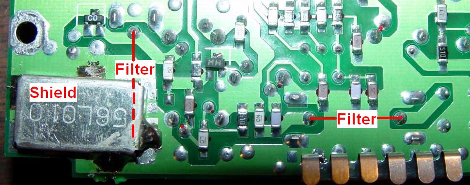
The front-end filters in these radios are easily identified: they have the part number stamped on top: DFC3R860P020BTD and say "GIGAFIL" on the side. They're made by Murata and are centered on 860 MHz with a bandwidth of about +/- 10 MHz. They will NOT pass a signal very well at 902 MHz. Toko makes filters, 6DFB-915E-10, which will fit the RF board; they're centered at 915 MHz with a bandwidth of +/- 13 MHz; not too many places sell them.
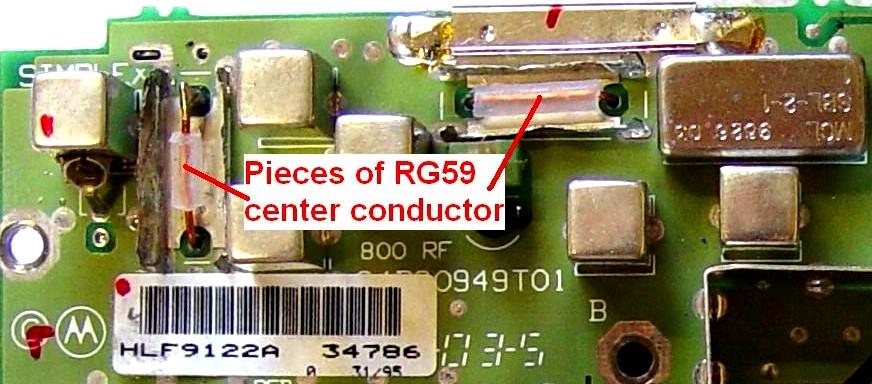
If you are able to obtain new filters, then by all means remove the existing ones and replace them. If not, don't despair; you can still make a very good receiver by just shorting out the existing filters. The procedure to do this is detailed here. All operations take place on the solder-side of the circuit board. The front-end schematic shows what you're actually doing. Blocking capacitors in the antenna switching network on the PA circuit board isolate the radio's antenna jack from the RF board's receiver input, eliminating the possibility of damage if DC is applied to the antenna. Click on the image for a larger view.
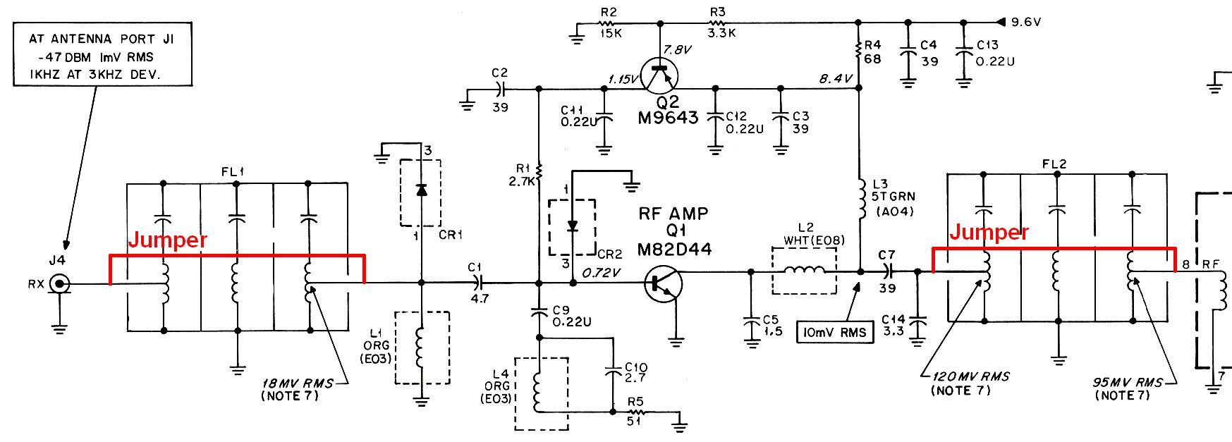
The terminals of the second filter, FL2, are completely exposed (right-side-filter in the photo), so you only need to add a short insulated piece of wire from the input pin to the output pin.
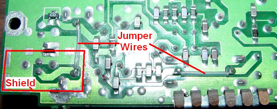
FL1's input lead is underneath a shield, which must be removed first. I find it helpful to remove any excess solder on the shield and on the circuit board in the areas where it will be reattached. Solder another short insulated piece of wire from the input pin to the output pins of this filter just like you did in the previous step.
You will need to cut a bit of metal away from the corner of the shield to allow the wire to pass through it when the shield is soldered back in place. A good strong pair of diagonal cutters will do the job.
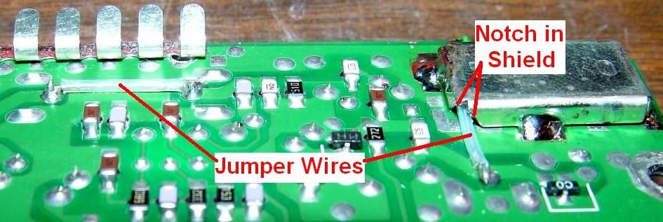
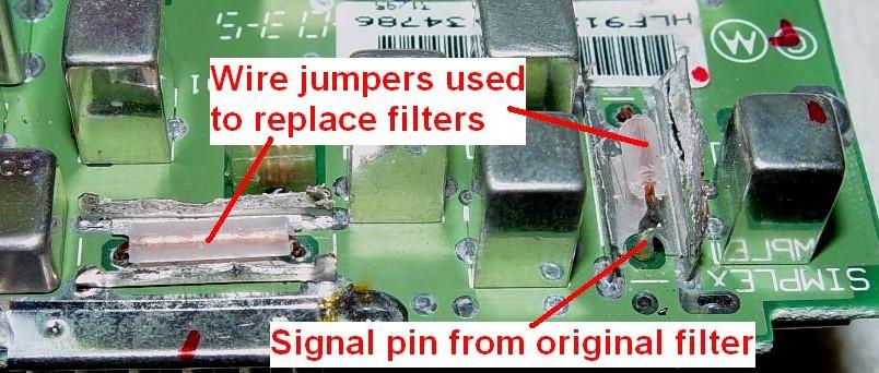
Another method that I've seen done, doesn't require the shield to be removed from under the RF board, nor does it require that the old filters be completely removed. You remove just the filter bodies from the top of the board by unsoldering the mounting clips from the metal filter body, spreading them slightly, and pulling up on the filter body. The metal clips remain soldered to the RF board. Three of the four signal pins - the ones that are accessible - are removed by unsoldering them. The remaining pin on FL1 - which is soldered under the shield - is left in place. An insulated jumper wire is inserted into the filter holes to make the circuit complete again. Attach the wire to the remaining signal pin on FL1. Here are two photos showing what this looks like:
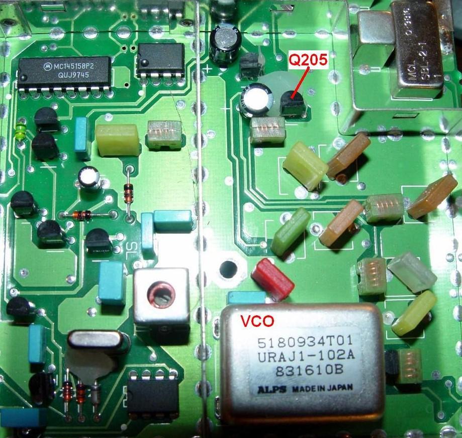
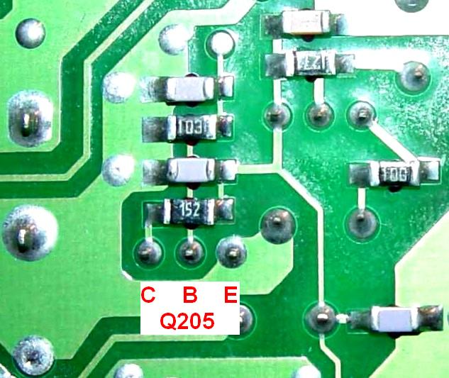
The final modification to the RF board consists of disabling the VCO range-switching transistor, Q205, shown here in the VCO area. The silver can labeled "5180934T01" is the actual sealed VCO.
There are several ways this can be done. The numbers shown on the RF board schematic in red refer to the options detailed below.
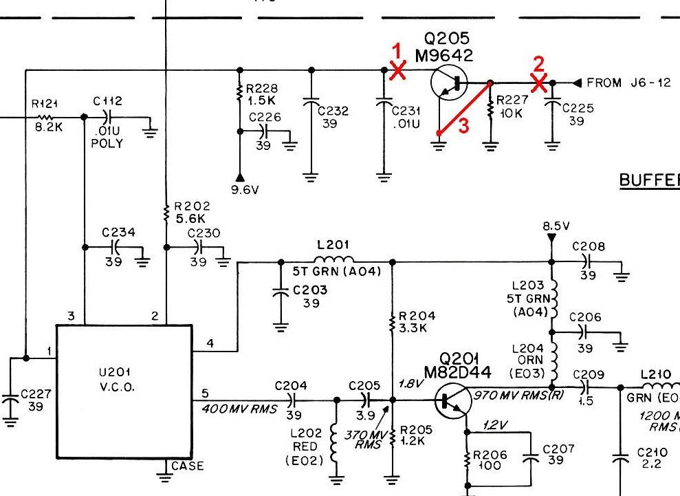
I don't like to destroy things when I make modifications, so I chose option 3 - shorting the emitter to the base. It's very easy to do. After locating Q205 on top of the board, flip it over and find its three leads. This picture shows you what to look for.
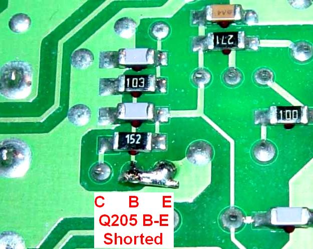
After adding a wire jumper from emitter to base, it should look like this. Note that insulation is NOT necessary since the two leads are very close together.
After dealing with the filters and Q205, you may replace the RF board back in the radio's chassis by reversing the removal steps.
Logic Board Changes:
NOTE: If you don't have access to the proper hardware, firmware, or software, you can skip this section and most of the next section, and just reprogram the radio with your desired frequencies. I just do all of this for completeness. You could go through the various alignment screens and write down the values, blank the board, then enter the old values or leave the defaults there. All of them are used only for transmitting, which this radio will never have to do, so they aren't critical (except entering the crystal and radio tuning values read from stickers inside the radio).
Since we're making a 902 MHz receiver, the radio will never be used for transmitting. The logic board will need its firmware replaced, its memory cleared, and its code plug programmed with fresh data.
The steps needed to replace the firmware are mechanically simple:
The rest of this procedure isn't so easy. This involves completely blanking the radio and loading new personality data. This must be done because the EPROM has been replaced, and the trunking data in the radio won't make sense to the new program.
New Programming:
You will need to use MaxTrac Lab software in order to blank the board (we leave it up to the reader to obtain this). Regular MaxTrac RSS software can be used for everything after that.
After blanking the board, you should use regular MaxTrac software to finish the process.
At this point, a screen will come up asking for product line, range, panel, etc. Note that "high signaling" is only available with 16-pin logic boards. Use the up/down arrows to find the appropriate product line and press Enter.
Then choose the model. Again, the up/down arrows allow you to scroll to the desired model. Enter your chosen selection.
For the frequency range, choose the 800 MHz range (806-870) using the up/down arrows.
The panel number will depend on your control head. Enter your choice:
The software will ask you for the model number. Scroll through the available choices and watch the various parameters on the right side of the screen. Choose a model number that has the options you want.
The serial number is next. Enter this information from the label on the heat sink of the radio.
Make sure you have everything entered properly, as you can NOT change any of this data, once you save it, without blanking the board and starting over again. If you're satisfied with the data, press F8 to save it to the radio.
You will now be sent to the Logic or RF board replacement procedure screen. There are several steps in this procedure. The steps must be followed in order, but you don't necessarily need to change any data in them. The screens will prompt you along the way.
Step 1 suggests you read the service manual for more information.
Step 2 deals with the reference crystal data. Press F2 to enter this adjustment. These labels are located inside the VCO compartment.
Note from WA6ILQ: The label glue can dry out. I've found the label (the "2674289" below) lying loose inside the radio on two occasions. I suggest you use a Sharpie pen and copy the number onto the adjacent sheet metal shield. The label on the crystal seems to have better glue, or maybe the wax or glue that is used to lock down the crystal and prevent microphonics helps to hold the label on... Even so, I still copy the crystal number onto the sheet metal shield as well. I used to copy the information onto the inside of the radio cover until I had two radios on the bench at once and caught myself swapping the covers as I put them back together.
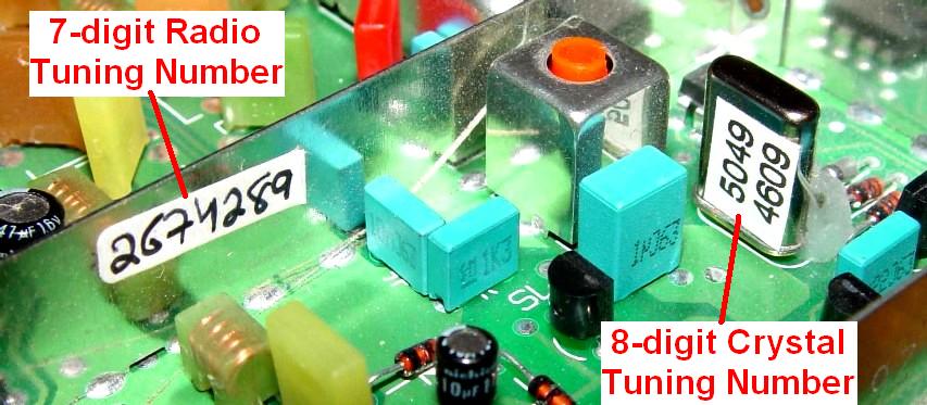
You will see the crystal with a label on it. Enter the top digits into the top crystal label line and enter the bottom digits into the bottom crystal label line. The tuning data is located on a label affixed to a compartment shield, or on the circuit board itself, and it has seven digits in it. On the screen, the first row has room for three and the second row holds the other four. Enter the digits into the two tuning data lines. Some labels will have the letter H at the beginning; enter this letter, if present, in the third row.
It will be necessary to accurately measure the voltage, with a digital voltmeter, on pin 1 of J6; that's the 14-pin connector that goes through the chassis to the RF board. It should be around 9.6 volts DC but you must get it accurate to two decimal places. Enter this into the area labeled 9.6V. Program this information by pressing F8.
You will be prompted to go to the screen for Transmitter Deviation calibration. Hit F3 to enter this and then press F8 to accept the defaults, as this radio will be used only for receiving.
Depress F4 for Transmitter Frequency Warp. This deals with adjusting the transmitter frequency. If necessary, set the value to 102 and hit F8 to program this value.
Press F5 for Transmitter Power Calibration and press F8 to accept the defaults, as this radio will not be used for transmitting purposes.
Transmitter Deviation Calibration is under F6. Use F8 to accept the default values.
Total Deviation with PL is accessed by pressing F7. Again press F8 to use the default settings.
We're almost done. Press F8 to access Total Deviation with Digital PL. You can accept the default values by pressing F8.
Finally, press F10 to exit the board replacement procedure. We recommend that you save the code plug data to an archive file, in case service is required at a later date. It will save you time reloading frequencies and other user data.
You can now exit this procedure and get back into the main menu. This radio can now be programmed as usual. Starting at the main menu, press:
You may need to create a new mode. Press F8 - MODE UTILITY and create one, then return to the CHANGE/VIEW screen and fill in the Rx Frequency. You will get a message when entering a 902 MHz frequency stating that it is out of range; just continue by depressing F2. You don't want to enter any transmit frequency (make it all blanks), but you will need to deal with any PL/DPL decoding schemes you may want. When you're finished, press:
All of the modifications are now complete.
The Results:
One RF board I tested already had FL1 replaced with a 915 MHz Toko unit, while FL2 was still the original 860 MHz unit. At 902.4125 MHz, this receiver required over 4 uV before all of the crackling noises went away. After the second filter was shorted out, the receiver was noise-free at 0.3 uV. Squelch broke below 0.1 uV and it reached 20dB quieting at 0.266 uV. However it also heard the image signal at 812.2125 MHz and it took about 40 uV for 20dB quieting on this frequency.
A second board, which was modified while writing this article, had both its filters shorted out. This unit made 20dB quieting with 0.237 uV, however with both filters defeated, a signal on the image frequency also made 20dB quieting at 0.317 uV. Clearly, the filters add just a bit of loss, but they also do a nice job of reducing image sensitivity.
If you use a MaxTrac converted this way (no input filters) near any signal source that's 91.2 MHz below your desired receive frequency, you WILL need some kind of filtering in the receiver. This can be accomplished by replacing the filters or adding an external filter ahead of it, such as a band-pass duplexer or filter, or both.
Eventually I obtained a second 915 MHz Toko filter and performed additional tests using the board with one 915 MHz filter already installed. The results are shown in the table below. The "FL1" column is the first front-end filter, closest to the antenna jack. The "FL2" column is the second front-end filter, between the RF amplifier and the mixer.
| FL1 | FL2 | 20dB Quieting Levels | |||
|---|---|---|---|---|---|
| 902.4125 MHz (main frequency) |
812.2125 MHz (image frequency) |
||||
| dBm | uV | dBm | uV | ||
| Shorted | Shorted | -119.0 | 0.251 | -117.0 | 0.316 |
| 915 MHz | Shorted | -118.0 | 0.282 | -75.0 | 39.764 |
| 915 MHz | 860 MHz | -94.0 | 4.462 | -56.0 | 354.393 |
| 915 MHz | 915 MHz | -118.0 | 0.282 | -40.0 | 2236.068 |
With one 860 MHz filter still installed, the radio lost about 25 dB of sensitivity at 902.4125 MHz. I would surmise that if both filters were the original ones, the receiver would lose about 50 dB, bringing the sensitivity down to -69.0 dBm or 79.339 uV.
The best receiver sensitivity was with both filters shorted out (as expected), which gave the least amount of pass-band loss. This also had the most undesirable image sensitivity, also as expected. The best overall performance was with both filters replaced. The converted radio broke squelch at -130.0 dBm or 0.071 uV. It required -127.0 dBm or 0.100 uV to open squelch with a 100.0 Hz PL tone deviated at 750 Hz. For one lousy dB of loss, I'll take 78dB of image attenuation any day of the week !
Additional testing on a fully converted radio with two 915 MHz filters installed showed better than rated sensitivity from about 897 MHz to a little above 933 MHz, or 915 MHz plus or minus 18 MHz. The filters are actually spec'd for plus or minus 12 MHz. The radio I used rapidly lost sensitivity below 890 MHz - it worked down to 870 MHz but the front end filters made it unusable there. This means that a properly converted 800 MHz MaxTrac could be used to receive the entire 900 MHz amateur band, and then some! Your mileage may vary, of course.
Acknowledgements and Credits:
Circuit information for MaxTracs was obtained from Motorola's official service manuals.
Dave N1OFJ told me how to modify the RF board. I wrote the article based on his directions and actually performed the steps and took pictures while doing so. He also provided the logic board initialization procedure.
Thanks go to the proofreaders who took the time to review this article for obvious errors: Dave N1OFJ and Scott KBØNLY. They were inspirational in getting me to write it.
Of course, Mike WA6ILQ of the Repeater-Builder web site staff deserves credit for converting the original Microsoft Word file to clean HTML.
Contact Information:
The author can be contacted at: his-callsign [ at ] comcast [ dot ] net.
Back to the top of the page
MaxTrac Index
Motorola index
Back to Home
Article text and all photos Copyright © 2005 Robert W. Meister, WA1MIK.
Schematics shown above are from the schematics in Motorola manual 6880102W84.
Hand-coded HTML Copyright © Michael R. Morris WA6ILQ 2005.
This page originally posted in May 2005.
This web page, this web site, the information presented in and on its pages and in these modifications and conversions is © Copyrighted 1995 and (date of last update) by Kevin Custer W3KKC and multiple originating authors. All Rights Reserved, including that of paper and web publication elsewhere.