Motorola index
Back to Home
By Robert W. Meister WA1MIK

|
MaxTrac index Motorola index Back to Home |
Motorola MaxTrac Secrets By Robert W. Meister WA1MIK |
|
This article is a compilation of communications and code plug information for the MaxTrac and Radius conventional (not trunking) mobile radios. Use this at your own risk. The author makes no claims as to the completeness or accuracy of the data contained herein. Be warned that if you write incorrect data to the radio you could corrupt the code plug, requiring a complete blanking and initialization with LAB RSS.
There is a lot of information packed into this article. Sometimes the most insignificant looking fact will be buried deep within a paragraph. Trust me, there are a lot of important details contained here.
Almost all of the information was gathered by examining memory and data sent to and from the radio. Additional programs were written as needed to collect, analyze, and compare the data. This is a work-in-progress and details will be added as more information is discovered.
Throughout this article, numerical quantities are decimal unless followed by the letter "h" indicating hexadecimal. The hexadecimal numbering system has values of 0 through 9 and A through F, corresponding to decimal values of 0 through 9 and 10 through 15 respectively. It is assumed that the reader knows about hex notation and the base-16 numbering system.
There are several topics that will be covered:
An additional topic will provide some data on the integrated circuits used in these radios.
Data Gathering:
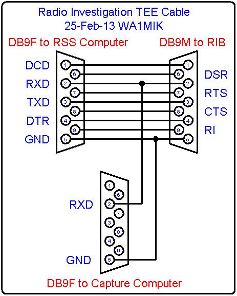
I treated the programming computer and the radio as black boxes. I knew what the RIB did and knew that I could connect a second computer in parallel with the first to capture either the transmit data or the receive data. Luckily the receive data line contained both the transmit and receive data streams. I made a "TEE" cable (see diagram below) with a male and female DE-9 connector at one end (to go between the RIB and the programming computer) and another DE-9 connector, wired to just the receive data line, to plug into the serial port of a second computer (a Dell laptop that I boot from an MS-DOS floppy disk). I had used this same configuration many years ago but was unable to figure out the communications parameters. Once I got past that hurdle, I wrote a short C program (all of my programming is in Turbo-C for MS-DOS) to capture the incoming data and write it to a disk file. I couldn't use the HyperTerm program because it only allows the standard serial port baud rates and I needed oddball speeds. At least this got me some useful data - until the baud rate changed.
I modified my program to recognize three of the incoming messages and change the speed accordingly. Once the data was captured in memory, I wrote it to a disk file. I also wrote another program to go through this raw data and print it to another disk file, this time indicating whether it came from the programming computer or the radio. I also converted the two-character values to individual hex bytes so I could view the data in a more convenient format.
I then spent hours and hours blanking an 800 MHz radio with LAB RSS, and programming it with various bands, power levels, model numbers, modes, etc. I also partially initialized the radio and varied the alignment values, saving the data sent to or from the radio, which I analyzed to see what changed and by how much. Some of the altered bytes in the code plug were not obvious as to function or value. I've gone just about as far as I think necessary at this time. I can collect just about all the data that's possible after completing the board replacement procedure.
I wrote another program to take data from several captured files and turn them into a CSV (comma-separated variable) format I could send to Excel. This made it easier to see where bytes changed.
I soon discovered that I could write any saved code plug to a blank radio, or that I could write a saved code plug to a radio that had been partially initialized, as long as the serial numbers matched. This let me put the radio back to its proper configuration after messing it up, so I could figure out what happens when I blank or initialize the radio.
Communications:
The primary method of talking to the radios is with Motorola's DOS-based Radio Service Software (RSS) programs. The programming computer uses its serial port to send data to, and receive data from, the Radio Interface Box (RIB). The RIB takes all data coming from the computer and sends it to the radio via a single wire (plus ground). The RIB takes all data on the single wire (going to the radio or coming from the radio) and routes it back to the computer. Only one device can transmit data at any time: either the computer is sending data to the radio, or the radio is sending data to the computer. The computer sees all data that it sends out, and it must ignore that data and only accept data sent by the radio. The computer is capable of sending and receiving data at the same time, but since only one wire is used for communications, the entire setup must perform these tasks separately and interleave them. The radio's microprocessor has circuitry similar to the RIB that separates transmit and receive data from the single programming wire. If both the computer and the radio transmit data at the same time, the results will be undetermined, although no harm will be done to the hardware.
I made a special cable that tapped the programming computer's receive data signal and fed that to a second computer that ran custom software to capture the data going to, and coming from, the radio. I was able to analyze these data streams to decode a lot of the information contained herein.
The Motorola MC68HC11 microprocessor (henceforth referred to as the CPU) has a full duplex serial port that is similar to the serial port in the programming computer. It supports multiple baud rates, parity, stop bits, etc. This port is initialized by code in the radio's firmware. The initial parameters select 7 data bits, even parity, and 1 stop bit (often called 7E1 in the PC-world) and the baud rate is determined by several divisor values, all based on the CPU clock crystal, which in the MaxTrac is 7.776 MHz. This frequency is divided by 4 (always done by the CPU) then by 128 (the divisor value chosen by the initialization code) then by 16 (clock cycles per bit) to get a final speed of about 949.22 baud. Note that this is NOT a standard baud rate, but that's just what it comes out to be with the crystal they used. The nearest possible speed for a PC-compatible computer's serial port is 115,200 divided by 121, which comes out to 952.1 baud. This is close enough (under 1% error) to the radio's speed.
RSS and the CPU initially communicate at this slow speed of about 950 baud, and the radio can always operate at this speed, but it's terribly slow, about 95 bytes per second. You don't want to transfer a lot of data at this speed.
With the use of even parity, the number of data bits is reduced to 7 bits per byte. This means that they need to use two 7-bit bytes to transfer one 8-bit byte of data, somewhat wasteful, but there's no real choice. The benefit of using a parity bit is additional data integrity. The number of 1-bits per byte must always be an even number (2, 4, 6, or 8) and the 0-bits must also be an even number (0, 2, 4, or 6). The serial hardware generates and detects this automatically, reporting an error if the parity is not correct. Parity can detect and correct a single bit error in each byte; this provides a limited robustness to the data. To help the process, each string of bytes (message) has an 8-bit checksum appended to the end of it. This checksum is calculated by adding (summing) all of the data bytes preceding it, then the value is negated and either sent at the end of the message or checked by the receiving program. When all the bytes in the message, including the checksum byte but not including the Lead-in character, are added together, the result will be zero.
To get around the inability to transfer 8-bit quantities, RSS turns each 8-bit data byte into two 4-bit ASCII characters with values from 30h to 3Fh. This makes them printable and easy to convert back to a single 8-bit byte. But this also doubles the length of any message, which means it now takes twice as long to send or receive data. Our 95 bytes per second is now less than 50 bytes per second.
RSS and the radio deal with this by shifting the communications speed to one that's 8 times faster (approximately 7,600 baud). A message is sent to the radio advising it to change speeds. The radio acknowledges the message, and all future communications then take place at the faster speed. When RSS wants to shift back to the slower speed, it sends a reset message at high speed, waits for the acknowledge message to be sent, delays about a second while the radio resets (and beeps), then queries the radio to see if it's alive at the slow speed. When an acknowledge message is received back from the radio, indicating it has completed its reset, processing continues.
Remember that only 7 bits of data are significant; the parity bit is automatically stripped off by the serial port hardware in both the programming computer and the radio's CPU.
Messages and Formats:
Messages are initiated by the programming computer (RSS) and are sent to the radio.
The radio sends its own messages back in response to received messages. The formats are
relatively simple: messages consist of four parts, in the following order:
The Lead-in byte is the only message component that is sent as one single
character; all other message components are sent as two hex/ASCII characters. The
Lead-in character is also NOT counted in the checksum. The possible values for the
Lead-in character are:
All other components after the lead-in are formed with two hex/ASCII characters per 8-bit value. The lead-in is the only true "binary" data value found in the data stream. The programming software can ignore all messages it sees that have a Lead-in of 04h, because these would be its own messages being returned back to it by the RIB. It just has to throw this data away and look for the 1Ch Lead-in.
The Header consists of several 8-bit bytes, in the following order:
The Null byte is required and could be construed as an extension of the function byte.
The Function byte determines the eventual function to be performed, such as read or write data.
The Byte Count is the number of data bytes, including a leading null byte, that are being sent or that RSS expects to receive.
The Address High and Address Low bytes form a 16-bit address within the CPU where data is to be read from or written to.
The message's Data bytes follow the header. The first data byte must be a null byte and this is counted in the byte count. So if you want to write just one byte of data, the Byte Count would be 02h and the data would consist of one byte of 00h followed by the single data byte you really want to write.
The Checksum follows the data bytes. It is an 8-bit sum of all of the bytes before it EXCEPT the Lead-in byte. Whenever a Lead-in byte is seen in a data stream, the internal checksum should be set to zero (00h) and future bytes would be added to this internal checksum. The sum is negated and transmitted at the end of the message. When the message has finished and all the bytes are added, this internal checksum should be zero (00h).
Recall that all 8-bit data bytes are sent as two printable hex characters by splitting the byte into two 4-bit nibbles that have the value 30h added to them. This operation is reversed during reception. The decoded (8-bit binary) data is what gets added to the checksum.
Message Examples:
So, how does this all work? One message that RSS can send to the radio essentially asks: "Hey, are you out there, connected, powered up, and alive?" This message begins with the 04h Lead-in byte, then the required Null byte, the Function code of 21h, zeroes for the Byte Count and Address bytes, no Data, and finally the Checksum. The Checksum value DFh plus the only non-zero data in the message (21h) equals 00h when added together, thus verifying the checksum. All of the data below are hexadecimal values.
| 04 | 00 | 21 | 00 | 00 | 00 | DF | Hex bytes | ||||||
| 0 | 0 | 2 | 1 | 0 | 0 | 0 | 0 | 0 | 0 | = | ? | ASCII chars | |
| 04 | 30 | 30 | 32 | 31 | 30 | 30 | 30 | 30 | 30 | 30 | 3D | 3F | Bytes sent |
If everything is connected and powered up, the radio responds with an Acknowledge message. This message begins with the 1Ch Lead-in byte, then the required Null byte, the Function code of 24h, zeroes for the Byte Count and Address bytes, and finally the Checksum. The Checksum value DCh plus the only non-zero data in the message (24h) equals 00h when added together, thus verifying the checksum. All of the data below are hexadecimal values.
| 1C | 30 | 30 | 32 | 34 | 30 | 30 | 30 | 30 | 30 | 30 | 3D | 3C | Hex chars |
| 0 | 0 | 2 | 4 | 0 | 0 | 0 | 0 | 0 | 0 | = | < | ASCII chars | |
| 1C | 00 | 24 | 00 | 00 | 00 | DC | Hex bytes | ||||||
If the radio is not happy with a message it receives, either because the checksum is incorrect, a parity error has occurred, or the message is invalid, the radio responds with a Negative Acknowledge message. This is the same as the Acknowledge message except the Function value is 25h instead of 24h and the Checksum is DBh instead of DCh.
There are several message categories: Simple, Command, Send Data, and Request Data. The
Simple messages have no Byte Count, Address, or Data bytes. Such messages include:
The Command messages include some data that is interpreted directly by the radio's
hardware, like "transmit on this frequency" which is used during alignment. Such messages
always contain some data. One that's used a lot is the message to shift communications to
another speed:
The full byte content of the message is 04h, 00h, 2Eh, 02h, 00h, 00h, 00h, 04h, CCh. This message has a Byte Count of two, an Address of 0000h, and Data bytes of 00h and 04h. The value 04h ends up being placed directly into the CPU's serial port baud rate divisor register and it selects a division of 16 instead of 128. This has the effect of setting the baud rate to be 8 times faster than what it originally was, so instead of 949.22 baud, the new speed is 7,593.75 baud. The nearest PC-compatible speed is 115,200 / 15 = 7,680 baud, about 1% faster.
The message to Send Data to the radio has two formats, depending on where the data
will end up: RAM or EEPROM. They both have Byte Counts, Addresses, and Data.
Writing to EEPROM requires a 10mSec delay per byte after the message has been sent. The radio returns an acknowledge (or negative acknowledge) message immediately upon verifying the correctness of the message, then proceeds to actually write the received data, that it temporarily stored in RAM, to EEPROM. It is up to RSS to wait the proper amount of time before sending another message, because the CPU is busy delaying and ignores anything sent to it during that time. This delay is not necessary when writing to RAM and apparently the external EEPROM writes significantly faster. Unfortunately, the radio doesn't wait until it has finished writing the data to the EEPROM before sending the Acknowledge message; this is a serious design error that we're stuck with.
The message to Request Memory Data from the radio contains a Byte Count and an
Address, but no data. The Byte Count is the number of bytes that the radio is supposed
to send back to the computer; it is NOT the data length of the request message.
Remember to add one extra byte to the Byte Count for the Null byte that precedes the
returned data; this makes the minimum Byte Count 02h.
The radio responds with its own message formatted similarly to the ones above, with
its own function code. This returned data also becomes the radio's way of acknowledging
receipt of the request message. The obligatory Null byte will be the first of the data
bytes returned and it is always ignored. I'm not sure why it's even there (possibly for
data alignment purposes).
If the computer wanted to read 8 bytes of data from the radio at address B600h, it
would send a message with a Lead-in of 04h, the required Null, a Function code of 79h, a
Byte Count of 09h (remember that extra null), an Address of B600h (sent as two bytes),
no Data, and the Checksum (C8h):
04h, 00, 79h, 09h, B6h, 00h, C8h
The computer would respond with a message with a Lead-in of 1Ch, the required Null, a
Function code of 38h, a Byte Count of 09h (the requested 8 bytes plus the null), an
address of B600h (sent as two bytes), the leading Null byte, the 8 Data bytes, and the
Checksum (28h):
1Ch, 00h, 38h, 09h, B6h, 00h, 00h, 20h, 43h, 4Fh, 50h, 52h, 2Eh, 27h, 38h, 28h
If you look at the data bytes, you'll see the beginning of the copyright string that's
displayed in the code plug contents below: " COPR.'8"
If the computer wants to write 8 bytes of FFh to the radio at address B600h, it would
send a message with a Lead-in of 04h, the required Null, a Function code of 59h, a Byte
Count of 09h (remember that extra null), an Address of B600h (sent as two bytes), the
Null byte (00h), the 8 Data bytes, and the Checksum (F0h):
04h, 00h, 59h, 09h, B6h, 00h, 00h, FFh, FFh, FFh, FFh, FFh, FFh, FFh, FFh, F0h
The radio would respond to this with an Acknowledge message (function code 24h):
1Ch, 00h, 24h, 00h, 00h, 00h, DCh
RSS transfers code plug (EEPROM) data in 8-byte blocks. You may notice that when RSS is reading or writing a code plug, it displays a progress bar on the screen that counts off the number of blocks read or written. 64 code plug blocks are present in the internal EEPROM, while another 256 code plug blocks are present in the external EEPROM, for a total of 320 code plug blocks. This is one of those times when the "AHA" bulb in your brain lights up!
There are times when RSS transfers data to the external EEPROM in 16-byte blocks. Some radios can handle this, some cannot. The internal (CPU) EEPROM can only deal with eight bytes at a time, and if your radio has no external EEPROM (as on the masked logic board), that's the largest transfer packet possible.
Memory:
These radios use the MC68HC11 microprocessor. This device contains 256 bytes of RAM, 64 internal hardware configuration registers and ports, and 512 bytes of EEPROM. Some may also contain 8,192 bytes of masked ROM. The logic board contains additional code plug EEPROM of 2,048 or 8,192 bytes and may contain firmware in an EPROM of up to 32,768 bytes.
An Application-Specific Integrated Circuit (ASIC) chip on most logic boards decides what addresses go to which particular logic components. It also converts some addresses to individual I/O signals that control operation of the radio. On the masked logic board (one with firmware internal to the CPU), there is no ASIC and the CPU performs all address decoding.
The table below describes the memory map of these radios.
| Hex Address | Usage and Location |
|---|---|
| 0000 - 00FF | Internal CPU RAM. |
| 0F00 - 0FFF | ASIC memory-mapped I/O. |
| 1000 - 103F | Internal CPU special function registers and ports. |
| 4000 - 5FFF | External RAM, usually only in trunking radios. |
| 6000 - 7FFF | 99-channel extended code plug space in external EEPROM. |
| 7800 - 7FFF | Extended code plug space in external EEPROM. |
| 8000 - B5FF | External program EPROM. |
| B600 - B7FF | Internal EEPROM (normal code plug space and tuning data). |
| B800 - FFFF | External program EPROM. Masked ROM: E000 - FFFF. |
The internal CPU special function registers and ports are described in the MC68HC11 reference manuals and won't be covered further in this article.
The tuning and alignment data and serial number are stored within the CPU's internal EEPROM. Depending on how many modes and features are present within the radio, the code plug data could be stored entirely within the CPU's internal EEPROM or split between the internal and external EEPROM. Only the 99-channel MaxTrac uses the 8,192 byte external EEPROM; all other radios have a 2,048 byte external EEPROM.
The external EPROM that stores the radio's firmware covers the address space from 8000h to FFFFh, but it has a gap in it where the CPU's internal EEPROM exists: B600h to B7FFh.
Code Plug Layout:
I blanked and initialized an 800 MHz radio on various bands and with various options, then captured and analyzing the data that RSS sent to the radio. By doing this multiple times, I could compare the bytes, see what changed, and figure out the various values.
The internal EEPROM runs from B600h to B7FFh. It contains data for up to 16 modes; radios with more modes force the mode data to be stored in the external EEPROM from 7800h to 7FFFh (or from 6000h to 7FFFh for the 99-channel MaxTrac). Also, certain features (signaling for example) may force the code plug data to move to the larger space in external EEPROM.
| ADDR | Contents, Usage, and Notes |
|---|---|
| B600h | spc |
| B601h | C |
| B602h | O |
| B603h | P |
| B604h | R |
| B605h | . |
| B606h | ' |
| B607h | 8 |
| B608h | 8 |
| B609h | spc |
| B60Ah | M |
| B60Bh | O |
| B60Ch | T |
| B60Dh | O |
| B60Eh | R |
| B60Fh | O |
| B610h | L |
| B611h | A |
| B612h | NUL (00h) |
| B613h | Serial Number |
| B614h | Serial Number |
| B615h | Serial Number |
| B616h | Serial Number |
| B617h | Serial Number |
| B618h | Serial Number |
| B619h | Serial Number |
| B61Ah | Serial Number |
| B61Bh | Serial Number |
| B61Ch | Serial Number |
| B61Dh | ??? (always 30h) |
| B61Eh | ??? (always 30h) |
| B61Fh | Product Line index # |
| B620h | Panel # |
| B621h | |
| B622h | |
| B623h | |
| B624h | Mode Address H (see note below) |
| B625h | Mode Address L (see note below) |
| B626h | Mode Address H |
| B627h | Mode Address L |
| B628h | Mode Address H |
| B629h | Mode Address L |
| B62Ah | Mode Address H |
| B62Bh | Mode Address L |
| B62Ch | Model Entry MDF # |
| B62Dh | Radio Series index # |
| B62Eh | Checksum: B600h-B62Dh |
| B62Fh | |
| B630h | |
| B631h | |
| B632h | |
| B633h | |
| B634h | |
| B635h | |
| B636h | |
| B637h | |
| B638h | |
| B639h | |
| B63Ah | |
| B63Bh | Band and Sub-Band value |
| B63Ch | Total Dev w/PL (hi), w/DPL (lo) |
| B63Dh | MDF 00h |
| B63Eh | Master TX Power MDF 0Dh |
| B63Fh | MDF 01h |
| B640h | CTRL B+ buckets 01-08 MDF 02h |
| B641h | CTRL B+ buckets 09-16 MDF 03h |
| B642h | |
| B643h | |
| B644h | Crystal Tuning Data? |
| B645h | |
| B646h | Crystal Tuning Data? |
| B647h | |
| B648h | |
| B649h | |
| B64Ah | |
| B64Bh | |
| B64Ch | |
| B64Dh | Crystal Tuning Data? |
| B64Eh | |
| B64Fh | |
| B650h | |
| B651h | |
| B652h | |
| B653h | |
| B654h | |
| B655h | |
| B656h | |
| B657h | |
| B658h | |
| B659h | 9.6V or V-Diode value |
| B65Ah | MDF 04h |
| B65Bh | MDF 05h |
| B65Ch | MDF 06h |
| B65Dh | Frequency Warp MDF 0Fh |
| B65Eh | Master Deviation MDF 0Eh |
| B65Fh | Pwr[01] Tuning Value |
| B660h | Dev[01] Tuning Value |
| B661h | Pwr[02] Tuning Value |
| B662h | Dev[02] Tuning Value |
| B663h | Pwr[03] Tuning Value |
| B664h | Dev[03] Tuning Value |
| B665h | Pwr[04] Tuning Value |
| B666h | Dev[04] Tuning Value |
| B667h | Pwr[05] Tuning Value |
| B668h | Dev[05] Tuning Value |
| B669h | Pwr[06] Tuning Value |
| B66Ah | Dev[06] Tuning Value |
| B66Bh | Pwr[07] Tuning Value |
| B66Ch | Dev[07] Tuning Value |
| B66Dh | Pwr[08] Tuning Value |
| B66Eh | Dev[08] Tuning Value |
| B66Fh | Pwr[09] Tuning Value |
| B670h | Dev[09] Tuning Value |
| B671h | Pwr[10] Tuning Value |
| B672h | Dev[10] Tuning Value |
| B673h | Pwr[11] Tuning Value |
| B674h | Dev[11] Tuning Value |
| B675h | Pwr[12] Tuning Value |
| B676h | Dev[12] Tuning Value |
| B677h | Pwr[13] Tuning Value |
| B678h | Dev[13] Tuning Value |
| B679h | Pwr[14] Tuning Value |
| B67Ah | Dev[14] Tuning Value |
| B67Bh | Pwr[15] Tuning Value |
| B67Ch | Dev[15] Tuning Value |
| B67Dh | Pwr[16] Tuning Value |
| B67Eh | Dev[16] Tuning Value |
| B67Fh | Tuning Data Checksum: B63Bh-B67Eh |
| B680h | Power Level fine tuning MDF 07h |
| B681h | Power Level fine tuning MDF 08h |
| B682h | MDF 09h |
| B683h | |
| B684h | |
| B685h | |
| B686h | |
| B687h | |
| B688h | |
| B689h | |
| B68Ah | |
| B68Bh | |
| B68Ch | Checksum B63Bh-B68Bh |
| B68Dh | Mode 1: B68Dh-B6A1h |
| B68Eh | |
| B68Fh | |
| B690h | |
| B691h | |
| B692h | |
| B693h | |
| B694h | |
| B695h | |
| B696h | |
| B697h | |
| B698h | |
| B699h | |
| B69Ah | |
| B69Bh | |
| B69Ch | |
| B69Dh | |
| B69Eh | |
| B69Fh | |
| B6A0h | |
| B6A1h | |
| B6A2h | Mode 2: B6A2h-B6B6h |
| B6A3h | |
| B6A4h | |
| B6A5h | |
| B6A6h | |
| B6A7h | |
| B6A8h | |
| B6A9h | |
| B6AAh | |
| B6ABh | |
| B6ACh | |
| B6ADh | |
| B6AEh | |
| B6AFh | |
| B6B0h | |
| B6B1h | |
| B6B2h | |
| B6B3h | |
| B6B4h | |
| B6B5h | |
| B6B6h | |
| B6B7h | More mode data follows; not shown |
| - - - | |
| B7BBh | Power-Up Delay value |
NOTE: For B624h, if the high byte is zero, the low byte indicates the number of active or selectable modes. Otherwise, these two bytes point to the first mode.
The data in the bytes marked "MDF nn" are obtained from the MDF file during radio initialization. These control transmitter power, deviation, frequency, and other unique features.
The various checksums are simple 8-bit checksums for the addresses indicated. The radio has one routine that it uses to calculate these checksums and it's the same one used to verify the serial communications messages. This same routine is also used to verify the contents of the program EPROM when the radio is first turned on.
You may note that the radio's model number is NOT stored within the code plug. In fact, a lot of information related to the model (band, output power, number of modes, etc) is not stored directly in the EEPROM. The three bytes at locations B61Fh, B62Ch, and B62Dh uniquely identify an entry in the MDF file provided with RSS. Once this entry is found, RSS knows about the other parameters like the band, output power, number of modes, etc. If you look in an MDF file, the final section contains model numbers and other data bytes; the three bytes ahead of the model number are stored in the three bytes mentioned in this paragraph. The MDF file can be searched for these three bytes to get the exact model number entry.
Similarly, the band split, frequency range, and talk-around ability are further specified by the byte at location B63Bh, shown below. Since the MDF file contains the actual frequency limits for programming the radio, these must be used by the radio to assist with synthesizer programming. I've never seen an L1-split MaxTrac.
| Bit# | Function/Use if ON |
|---|---|
| 80h | Unknown |
| 40h | Unknown |
| 20h | Talk-Around (800/900 only) |
| 10h | Split (2 bits) |
| 08h | |
| 04h | Unknown |
| 02h | Band (2 bits) |
| 01h |
Split values (two bits, approximate frequencies):
0 = VHF Low 1 (22.5-30), UHF 1 (403-430), VHF High 1 (136-162), 800 MHz
1 = VHF Low 2 (30-36), UHF 2 (440-470), VHF High 2 (146-174), 900 MHz
2 = VHF Low 3 (36-42), UHF 3 (470-490)
3 = VHF Low 4 (42-50, UHF 4 (490-512)
Band values (two bits, approximate frequencies):
0 = VHF High (136-174)
1 = UHF (403-512)
2 = 800/900 MHz
3 = VHF Low (22.5-50)
The 16 individual power and deviation tuning values (pairs) are stored at locations B65Fh through B57Eh. These are positive offsets from the master power and deviation values at location B63Eh and B65Eh (respectively). The Total Deviation with PL and DPL are 4-bit values that are subtracted from a maximum value of 15. These reduce the total deviation when modes add PL or DPL.
The 9.6V and V-Diode voltage measurements are calculated by a somewhat convoluted equation.
The Power-Up Delay value is in increments of approximately 17 milliseconds.
Some of the tuning data is still unresolved, however enough has been decoded to recover all the tuning data you'd need to re-enter in the Board Replacement procedure in RSS.
When a radio is blanked with LAB RSS, you are given the opportunity to specify a normal or extended code plug, and whether you want to retain or erase the tuning data. RSS reads the CPU's EEPROM, fills it with spaces and FFh bytes, and writes this back to the CPU's EEPROM. If you specify an extended code plug, it fills the entire extended EEPROM with FFh bytes. If you remain within LAB RSS to initialize the radio, RSS continues to work with the existing code plug data now in the computer's memory, if you asked it to retain the tuning data. If you exit LAB RSS and initialize the radio with another copy of RSS, then no tuning data will exist, even if you told LAB RSS to retain it. The retention is only valid if you remain within LAB RSS.
Mode Data:
The info presented below is missing some data that pertains to the 900 MHz radios. More analysis is needed in this area.
The first mode is normally stored in the CPU's EEPROM starting at location B68Dh, unless the mode data has been sent to the external EEPROM. The layout is still the same. Each mode is 21 bytes long. The fields marked "Mode Address H" and "Mode Address L" in the memory map above will contain values between 6000h and 7FFFh if the modes are being stored in the external EEPROM; these fields will have other values in them when the modes are being stored in the CPU's EEPROM.
| Offset | Size | Function/Use/Value |
|---|---|---|
| 00 | 1 | 2Fh, or 80h+displayed mode # [1] |
| 01-02 | 2 | RX Frequency or Offset [2] |
| 03-04 | 2 | TX Frequency or Offset [2] |
| 05-06 | 2 | RX Coded Squelch Value [3] |
| 07-08 | 2 | TX Coded Squelch Value [3] |
| 09 | 1 | Coded Squelch Type Byte [4] |
| 10 | 1 | ? |
| 11 | 1 | ? |
| 12 | 1 | Timeout value in seconds |
| 13-14 | 2 | Address of signaling system data |
| 15 | 1 | ? |
| 16 | 1 | ? |
| 17 | 1 | Always FFh? |
| 18-19 | 2 | Scan list address or bitmap [5] |
| 20 | 1 | Checksum of previous 20 bytes |
NOTES:
[1]: 2Fh is the default beginning of the mode entry. If the mode number to be displayed
is different, this byte will have 80h plus the desired mode number. Not all radios can
display an alternate mode number.
[2]: The frequency is coded as the number of steps needed to get to the frequency, plus some base frequency value. For example, a VHF radio on 50.000 MHz would encode the frequency as (50,000 kHz - 0 kHz) / 5 kHz = 10,000 or 2710h, while a UHF radio on 450.000 MHz would encode the frequency as (450,000 kHz - 402,950 kHz) / 5 kHz = 9,482 or 250Ah. Note that these radios cannot operate below their base frequency, and there is an upper limit for each band: (32,767 * Step Size) + Base Freq. See the table below. A value of FFFFh indicates a blank TX or RX frequency. Both frequencies are exactly what got entered into RSS. The receive offset is handled by the radio's firmware, which also converts this data to values needed to program the synthesizer on the RF board. Note that some bands use high-side injection (where the receiver oscillator is higher than the desired receive frequency) while others use low-side injection. This is also shown in the table below.
| Band | Base Freq kHz | Step Size kHz | Max Freq MHz | Injection MHz |
|---|---|---|---|---|
| VHF-L | 0.0 | 5.0 | 163.8350 | +10.70 |
| VHF-H | 136,000.0 | 5.0 | 299.8350 | -45.10 |
| UHF | 402,590.0 | 5.0 | 566.4250 | -45.10 |
| 800 | 804,862.5 | 12.5 | 1,214.4500 | -45.10 |
| 900 | 894,400.0 | 12.5 | 1,303.9875 | -39.15 |
Also, the frequency can be divisible by 6.25 kHz but is typically a multiple of 12.5 kHz. In this case, the most significant bit of the frequency bytes is turned on, and this is what limits the data to a maximum of 32,767 steps. If this bit is set, different base frequencies and step sizes govern the actual operating frequency (not shown in the table above).
[3]: For DPL, the exact code is stored in the two-byte field. For example, DPL code 311 (octal) = 00h, C9h. For PL, the TX value is exactly half of the RX value. A lower value means a higher PL frequency. To convert the decimal value to the PL frequency, divide 4861000 by the RX PL value, use the integral portion then divide by 10 to get tenths of a Hz resolution. For TX PL, divide 2430500 by the PL value then divide by 10.
[4]: Flag byte after RX/TX coded squelch values:
| Bit# | Function/Use if ON |
|---|---|
| 80h | Unknown |
| 40h | Activate CPU crystal shift |
| 20h | RX DPL INV (with RX DPL bit) |
| 10h | TX DPL INV (with TX DPL bit) |
| 08h | RX DPL |
| 04h | RX PL |
| 02h | TX DPL |
| 01h | TX PL |
Obviously no more than two of the low four bits can be on at any time: either (01 or 02) and (04 or 08). No bit implies Carrier Squelch or no PL/DPL for the receiver or transmitter. It's odd that the Radius and MaraTrac RSS allow Inverted DPL but the MaxTrac RSS doesn't, even though there's a text string to support it.
The CPU crystal shift is used on some radios to slightly shift the CPU crystal speed to eliminate birdies and interference on some frequencies related to the 7.776 MHz crystal.
[5]: The scan list bitmap tells which modes are in the scan list. Mode 1 is included if the most significant bit in the first byte is on, etc. The type of scanning (Priority or Non-Priority) doesn't seem to be a factor. Specifying either type sets the bit on to include that mode in the list. Each mode has its own list of up to 16 modes. Because each mode entry only has two bytes devoted to the scan list, each mode can only have up to 16 modes in the scan list, and they can only be composed of the first 16 modes. This list may change in radios that have more than 16 modes (the scan list is totally different in the MaraTrac radio, for example).
| Bit# | Ofs 18 Bits | Ofs 19 Bits |
|---|---|---|
| 80h | Mode 1 | Mode 9 |
| 40h | Mode 2 | Mode 10 |
| 20h | Mode 3 | Mode 11 |
| 10h | Mode 4 | Mode 12 |
| 08h | Mode 5 | Mode 13 |
| 04h | Mode 6 | Mode 14 |
| 02h | Mode 7 | Mode 15 |
| 01h | Mode 8 | Mode 16 |
For radios with 16 modes or less, when the code plug data all fits within the CPU's internal EEPROM space, the scan list bytes are the bitmap for the modes that are to be included when scanning.
For radios with more than 16 modes, when the code plug won't fit within the CPU's internal EEPROM space, the two bytes in the mode are an address of an additional 8-byte field that contains a four byte scan list bitmap. Each mode extension area is set up as shown in the table below (Ofs = byte offset).
| OFS | Contents |
|---|---|
| 0 | 11h, some sort of marker/indicator |
| 1 | Scan list bitmap for modes 17-24 |
| 2 | Scan list bitmap for modes 25-32 |
| 3 | Scan list bitmap for modes 1-8 |
| 4 | Scan list bitmap for modes 9-16 |
| 5 | FFh, unused? |
| 6 | FFh, unused? |
| 7 | Checksum of previous 7 bytes |
The bitmap bits are encoded the same way as when they're in the mode data itself. They just ran out of room and had to extend the mode entry, so the mode data resides in the extended EEPROM space and they used the internal EEPROM space to hold the extra mode data (scan list, so far).
Miscellaneous:
There are tables of data spread throughout the firmware that are similar to the Base Freq / Step Size table above. These are used to determine the 16 tuning frequencies. These are also used to determine which of the 16 tuning values is to be used for a given transmit frequency. RSS and the radio know what the tuning frequencies should be, so changing them in the program has no change on the tuning frequencies used internally by the radio's firmware when a particular mode is selected. It is not known if the tuning values are selected when the mode is changed or if a table is created in the CPU's RAM when the radio is turned on. The CPU determines an index value (0 to 15) based on the tables in the firmware, and this index value is then used to select the appropriate power and deviation tuning value from the tuning data in the CPU's EEPROM. If the transmitting frequency is such that this index value is lower than 0 or higher than 15, some other byte of data in the code plug will be used as the tuning value, and erratic operation will result. This is what happens on a 900 MHz radio when you transmit outside the expected 896-902 MHz or 935-941 MHz ranges; the radio can't properly determine which tuning value to use so it grabs some random byte of data in the EEPROM and uses that to calculate the transmit power and deviation, usually with unwanted results.
One way to fix this problem is to redefine the base frequency and step size in the 900 MHz firmware and alter the alignment frequencies present within RSS to match, such that operation in the 902-928 MHz band generates the proper index into the tuning values. This would require a major overhaul of the firmware and software.
Another way was sent to the author anonymously. The code that chooses the proper tuning value of the 16 present in the EEPROM, can be modified so the radio uses the first value for all transmit frequencies. This will at least keep the power and deviation under some reasonable control, however it will be a compromise over the entire operating range of the radio, so you'll have to play with the alignment values. You'll need an EPROM burner as the changes have to be made in the radio's firmware. Calculate the 8-bit checksum of the EPROM in two ranges: 8000-B5FF and B800-FFFF and write these down, as you'll need to correct them later. Look for the sequence of hex bytes CEB65F3A and change the "3A" to "01". You should find this in two places. Recalculate the checksum and change B5FF if the lower half needs correcting. Change FF9D if the upper half needs correcting. If your EPROM image file is 32kB, subtract 8000 from the addresses shown above. Burn a new EPROM and install it in the radio. You'll then have to check the deviation and power alignment. I suggest you set all 16 tuning values to the same number, then adjust the master deviation and power to get the radio to perform as you desire. It will be a compromise but at least the radio will work well out-of-band.
When a radio is blanked by LAB RSS, the entire code plug EEPROM space is filled with FFh bytes, except the 10-byte serial number field, which is filled with spaces (20h). There's no reason to fill the external EEPROM, as it will only be used if/when the internal EEPROM space can't hold all the mode information. I believe RSS considers a radio's logic board to be blank, and thus require initialization, if the serial number field is blank.
Cloning a radio is a process that's done entirely within RSS. It requires that both the source and target radio's code plugs exist as disk files first, then it reads them, merges the appropriate mode data while leaving the tuning data and serial number fields alone, then writes the target code plug back to disk. You complete the job by writing that code plug to the target radio.
Someone sent me an old blanking program that was used before LAB software was available. Along with that program was a "blank" data file that contained the exact pattern described in the previous paragraph. Apparently this program would write that data file as a code plug to the radio, thus blanking it. Simple yet elegant.
You can write any code plug file to the radio as long as the serial numbers match. You can write any code plug file to the radio if the serial number field in the radio is blank. If you save a radio's code plug to disk with RSS, you can then blank the radio and reload the saved code plug. This restores all of the information that was present. The code plug file on disk is actually a memory image of the EEPROM areas in the radio. Unfortunately (probably for security reasons), RSS encrypts the code plug file on disk for trunking radios.
The various code plug checksums are recalculated and/or written when RSS works with data in that particular area. For example, changing any of the tuning data values and saving it to the radio fixes the checksum at location B67Fh.
I wrote a program, initially for DOS, then for Windows, to remove my dependency on
LAB RSS. This program is not for sale and I will not give it to anyone, so don't even
ask! It lets me do the following to MaxTrac, Radius, and MaraTrac radios:
There are fields within the internal EEPROM data that indicate when mode data is stored in the external EEPROM, so the program knows when it needs to read or write this additional data. The program handles 2,048 or 8,192 byte external EEPROM.
Integrated Circuits:
The ICs used in these radios usually are stamped with just a Motorola part number; they often only provide the last five characters of the full part number. For example, a part such as 5180135C10 might be stamped 35C10. The numbers provided below are standard non-Motorola parts.
The front panel seven-segment display driver chip is an MM5484.
On the logic board, the voltage-controlled attenuator that controls the transmit deviation is part number AN5262. The six-channel six-bit digital-to-analog converter that controls transmit power and warp frequency, as well as the splatter filter and HearClear on the 900 MHz board, is part number MC144110. The 2Kx8 EEPROM is part number AT28C16 and the speed doesn't seem to be critical; 120, 150, or 200nS seems to work. Older radios had a Dallas DS1220 static RAM that used a lithium battery for data retention. These go bad after 15-20 years. They can be unsoldered and replaced with the AT28C16 parts.
On the RF board, the phase-locked-loop frequency synthesizer chip seems to be part number MC145158. The pre-scaler seems to be part number TD6127BP. The receiver IF chips don't seem to have a standard equivalent, and the one used on 900 MHz radios is not the same as on the VHF/UHF/800 MHz radios.
Credits and Acknowledgements:
The spark that lit my fire to work on this subject came from Ken AJ4KS who figured out the serial protocol and most of the message formats. He also disassembled much of the program firmware and proceeded in that direction. I analyzed data flowing between the radio and RSS and developed my own program and agenda. Ken and I shared ideas, data, and theories, and verified each other's findings and information during the spring of 2011.
Motorola, MaxTrac, Radius, MaraTrac, RSS, RIB, PL, DPL, and a whole bunch of other terms are trademarks of Motorola Inc.
Contact Information:
The author can be contacted at: his-callsign [ at ] comcast [ dot ] net.
Back to the top of the page
Up one level (MaxTrac index)
Up two levels (Motorola index)
Back to Home
This page created on Sunday 18-Sep-2011.
Article text, artistic layout, and hand-coded HTML © Copyright 2011 by Robert W. Meister WA1MIK.
This web page, this web site, the information presented in and on its pages and in these modifications and conversions is © Copyrighted 1995 and (date of last update) by Kevin Custer W3KKC and multiple originating authors. All Rights Reserved, including that of paper and web publication elsewhere.