Motorola index
Back to Home
Logic Board
Jumpers And
Connectors
By Robert W. Meister WA1MIK

|
MaxTrac index Motorola index Back to Home |
MaxTrac Logic Board Jumpers And Connectors By Robert W. Meister WA1MIK |
|
The MaxTrac and Radius mobile radios contain a microprocessor-controlled logic board that determines the features, operating modes, and accessories. The main difference is the number of pins on the accessory connector: 5 or 16. Most owners prefer radios with 16-pin accessory connectors.
Logic Board Jumpers:
Each logic board contains one or three jumpers that the user can configure. These are similar in function to those found in a GM300, although the GM300 has additional jumpers. (See the companion GM300 article here.) Each jumper consists of a three-pin header with a jumper plug that can be positioned to connect the center pin to either outside pin. The jumper plugs are usually black plastic, although other colors are also available.
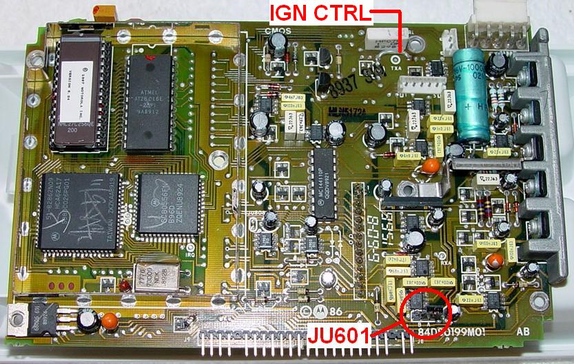
Here's a 5-pin board, HLN5172, with its one jumper (JU601) circled. Note that only the positions (A or B) are silk-screened on the boards with only one jumper. The location of this jumper may vary on other 5-pin boards.
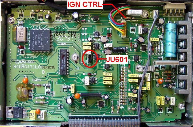
Here's a masked 5-pin board, HLN9123, for comparison:
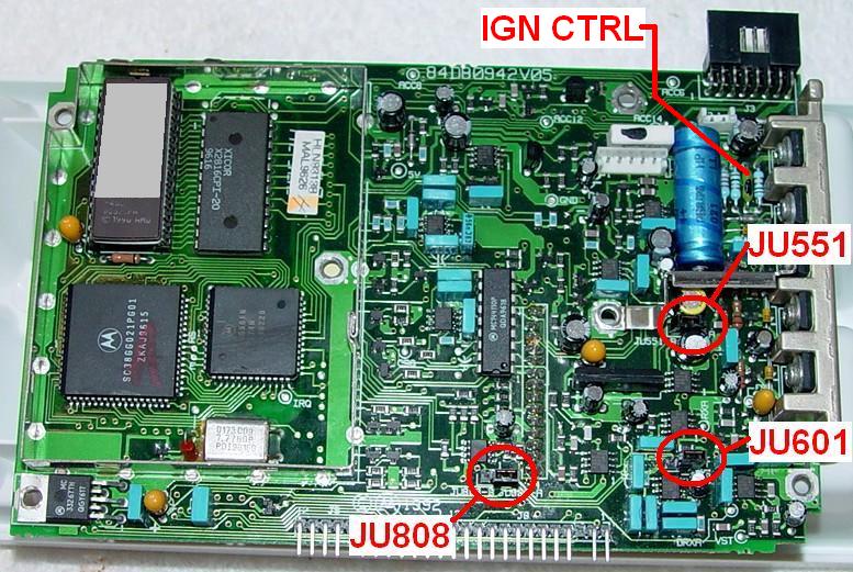
Here's a 16-pin board, HLN9313, with all three of its jumpers circled. All the jumper designations, as well as their positions, are silk-screened on the 16-pin boards:
Some boards may label these jumpers P551, P601, or P608. They are the same as the JU numbers shown below. All 5-pin logic boards have one jumper, JU601. Such boards are HLN5172, HLN5173, and HLN9123. Any of these models can have an A or B suffix. There may be additional board numbers for Radius radios.
All 16-pin logic boards have three jumpers, JU551, JU601, and JU808. The MaxTrac manuals document two boards: the HLN9313 for the VHF/UHF/800 MHz radios, and the FRN5529 for the 900 MHz MaxTrac only. Any of these models can have an A or B suffix. There may be additional board numbers for Radius radios.
The following table describes the functions and the default position of each jumper. The default position is indicated by the number of accessory jack pins (5 or 16) shown within parentheses.
| Jumper | Position | Function |
|---|---|---|
| JU551 | A | RX Audio on pin 11 not muted, not de-emphasized |
| B (5,16) | RX Audio on pin 11 muted and de-emphasized | |
| JU601 | A (16) | RX High-Speed Data after 300 Hz high-pass filter |
| B (5) | RX High-Speed Data before 300 Hz high-pass filter | |
| JU808 | A (5,16) | ACC jack pin 12 is programmable input/output |
| B | ACC jack pin 12 used for SCI programming |
The default position for JU601 depends on the logic board in use. On 5-pin logic boards, position "B" is the default. On 16-pin logic boards, position "A" is the default. This jumper would only be used for applications where the receiver is expecting high-speed data that the microprocessor must decode. Position "B" lets signals below 300 Hz get through; position "A" removes low-frequency signals. For amateur use, the jumper position is unimportant; you can set it to position "A" if it makes you happier.
Ignition Control Jumper:
This jumper is removed when you wish to use ignition control on your radio. Without it, you will need to supply nominal 12V to both the main DC plug as well as the proper pin on the accessory plug, to allow the radio to turn on and operate. These pins are described in detail in another article in the MaxTrac section of this web site.
The ignition control jumper is indicated on each of the photos above. On the 5-pin logic boards it's a piece of insulated wire or a zero-ohm jumper - a piece of wire that looks like a 1/4-watt resistor but has only one black band centered on a white or tan body. On the 16-pin logic boards, it's a small green 2A fuse that sits between some other 1/4-watt resistors. The schematics refer to it as F801 on some drawings or JU801 on others. If your radio has a blown ignition fuse, it can be replaced with a low-value (1-3 ohm) resistor.
Logic Board Connectors:
The MaxTrac logic boards have three major connectors on them:
These connectors are indicated in the photo below:
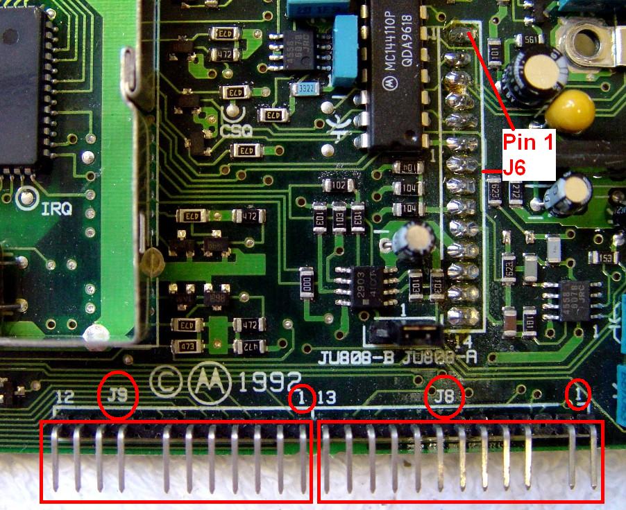
The J6 connector signals are different for the 900 MHz MaxTrac. The pins have the following signals:
| Pin | J6 Signal Names | |
|---|---|---|
| # | V/U/800 MHz | 900 MHz |
| 1 | +9.6 Volts | +9.6 Volts |
| 2 | Squ. Output | Squ. Output |
| 3 | Det. Audio | Det. Audio |
| 4 | T/R | T/R |
| 5 | Synth. Lock | Synth. Lock |
| 6 | Synth. Data | Synth. Data |
| 7 | Synth. Clock | Synth. Clock |
| 8 | Synth. L.E. | Synth. L.E. |
| 9 | Freq. Ctrl. | RSSI |
| 10 | VCO Mod. | VCO Mod. |
| 11 | Ground | Ground |
| 12 | Pin Shift | Freq. Ctrl. |
| 13 | Ref. Mod. | Ref. Mod. |
| 14 | Temp. Sense | Pin Shift |
The J8 connector signals are different for the 900 MHz MaxTrac. The pins have the following signals:
| Pin | J8 Signal Names | |
|---|---|---|
| # | V/U/800 MHz | 900 MHz |
| 1 | V.C. Top | V.C. Top |
| 2 | V.C. Wiper | V.C. Wiper |
| 3 | Keyway | Keyway |
| 4 | Hdset Audio | Not Used |
| 5 | Switched B+ | Switched B+ |
| 6 | Incoming B+ | Incoming B+ |
| 7 | SCI+ | SCI+ |
| 8 | PB1 | +9.6 Volts |
| 9 | PB2 | Hear Clear |
| 10 | Ground | Ground |
| 11 | PTT | PTT |
| 12 | Mic. Audio | Mic. Audio |
| 13 | Hook Switch | Hook Switch |
The J9 connector signals are the same for all MaxTrac and Radius models. The major difference is whether the display is two-channel (four LEDs, two push-button switches) or multi-channel (three LEDs, 3, 4, or 5 push-button switches, 6, 8, 16, or 32 channels displayed on two seven-segment LEDs). Some of the push-button switches may have different functions depending on the radio model and front panel escutcheon. The pins have the following signals:
| Pin | J9 Signal Names | |
|---|---|---|
| # | Two-Channel | Multi-Channel |
| 1 | TX/Busy LED | TX/Busy LED |
| 2 | Not Used | Display Enable |
| 3 | Monitor LED | Middle Switch |
| 4 | Mode LED | Right Switch |
| 5 | Monitor Switch | Down Switch |
| 6 | Busy LED | Left Switch |
| 7 | Mode Switch | Up Switch |
| 8 | Keyway | Keyway |
| 9 | +5 Volts | +5 Volts |
| 10 | Not Used | Display Data |
| 11 | Not Used | Display Clock |
| 12 | Ground | Ground |
If you disconnect the display board on a radio programmed for three or more channels, the radio will not transmit. The display board provides pull-up resistors on J9 pins 3, 4, and 6, and when disconnected, pull-down resistors on the logic board will make the radio think that you have pushed all three of the switches under the display at the same time. If you must operate the radio without a display board, you need to pull J9 pins 3, 4, and 6 up to +5V (J9 pin 9) through 10k 1/4w resistors to simulate what the display board does.
This situation is not a problem for two-channel radios.
Acknowledgements and Credits:
This information was extracted from Motorola MaxTrac, Radius, and GM300 Service Manuals. These model names are trademarks of Motorola, Inc.
Photos of the logic boards were taken by the author.
Contact Information:
The author can be contacted at: his-callsign [ at ] comcast [ dot ] net.
Back to the top of the page
Up one level (MaxTrac index)
Up two levels (Motorola index)
Back to Home
This page originally posted on Monday 09-Jul-2007
Article text, photos, artistic layout, and hand-coded HTML © Copyright 2007 by Robert W. Meister WA1MIK.
This web page, this web site, the information presented in and on its pages and in these modifications and conversions is © Copyrighted 1995 and (date of last update) by Kevin Custer W3KKC and multiple originating authors. All Rights Reserved, including that of paper and web publication elsewhere.