Up one level (MaxTrac index)
Up two levels (Moto index)
Back to Home
|
|
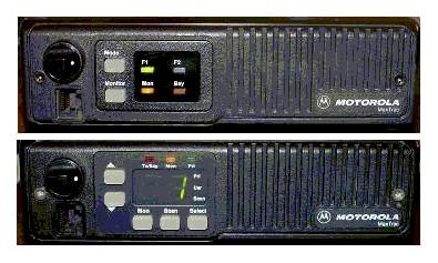
Introductory Information on the MaxTrac, Radius
and GM300 series radios, the DeskTrac station, and the
GR300, GR400 and GR500 series prepackaged repeaters
Formerly Maintained by Robert Meister WA1MIK
Currently Maintained by Mike Morris WA6ILQ.
Compiled By Mike Morris WA6ILQ from information provided by
Neil Johnson WBØEMU, Scott Lichtsinn KBØNLY,
Bob DeMattia K1IW, Eric Lemmon WB6FLY (SK),
Robert Meister WA1MIK (SK), Jeff Kincaid W6JK,
Will Martin KA6LSD (SK), Neil McKie WA6KLA (SK),
and Don Best N6ALD.
Photos by WA6ILQ unless noted.
Corrections and additional contributions are invited.
|
|

|
This page is oriented towards the USA marketed radios, simply because it was
compiled by USA residents; we described the radios we are familiar with.
If anyone would care to share information on the non-USA radios we'd be happy
to add them on this page, or even create a region-specific page.
Note: Any prices mentioned on this page (or on any page at this web site)
should be taken only as a rough guideline. This particualr article was written
in early 2006. Motorola adjusts prices quarterly,
and offers one set of prices to their dealers / service shops (the so
called "NSO" ("National Service Organization") Pricing), another on their telephone
order desk (i.e. retail sales), and a third to "self-maintaining" fleet customers
(i.e. those that have their own radio shops... cities, counties, police departments,
fire departments, etc). Prices are changed quarterly, so use the mentioned
prices only as a rough indication. If you encounter a large price change on
anything where we've mentioned a price we'd appreciate an emailed update.
Note that Motorola numbers their manuals with a part number starting with
68P, then 68-, and currently 68. The first version is identified with a trailing
"-O" (meaning "original"), and the first revision is a -A, then the second is a -B,
etc., skipping over "-O" if / when they get to it.
The MaxTrac, Radius and GM300 series fathered additional radio designs that
are / were sold all over the world, and the products were customized for the
local marketplace with region-specific model numbers like GM320, GM340 and GM900.
As one example the UK / European region has models that are never seen in the USA.
If anyone knows the differences / equivalences we'd appreciate the information.
As one specific example of non-local radios, Moto Australia makes
64 channel Radius mobiles and 16 channel GP300 handhelds that
cover 220-240 MHz for the Asian market (specifically the Philippines).
Those radios would be very popular in the USA Amateur market for the
219-220 and 222-225 MHz amateur bands.
Next, an eBay warning:
Attention EBay buyers:
1) No matter WHAT the model tag says, no MaxTrac, Radius, M-series
or GM300 mobile will ever operate over the entire frequency range listed
on its model tag / label. Each unit will do only a
portion of that model tag frequency spread, called a "split",
a "bandsplit" or a "range". This is due to the design,
and the design follows the laws of physics. In short, if you buy the wrong
range radio for your application (one example is a GM300 built for
490-520 MHz and you want to use it on a 462 MHz GMRS frequency)
you will have a nice doorstop. It is not practical to range-change
a MaxTrac, Radius, or GM300 series radio.
On the MaxTrac (which includes the MaxTrac 50 and MaxTrac 300 models), the
Radius "LRA" (which includes the M100, M120, M204, M208, M214 and
M216 models) and GM300 series (which includes the M10, m120, M130 and GM300 models)
radios the third character in the model number indicates the frequency band
where a 1 indicates 30-50 MHz (low band),
a 3 indicates 136-174 MHz (high band), and
a 4 indicates 406-520 MHz (UHF). A 5 indicates
either 800 or 900 MHz, later on 5 was reserved for 800 MHz and a
7 indicated 900 MHz.
- MaxTrac "MGA", "MJA", "MQA", "MWA" series:
Unfortunately, there are only two ways to determine the split of your radio. You
have to either open the radio up and look at the part number of the RF board, or you
have to read the radio (with the appropriate Motorola Radio Service Software,
commonly called RSS). If radio programming, the RIB and the RSS are new to you
then I suggest you read the "RSS and RIB" page on the Motorola page at this web
site, and scroll down on this page to the heading below titled "Programming and
the Radio Service Software (RSS)". UHF MaxTracs were made for 406-430 MHz
and for 449-470 MHz. Operation below 449 MHz (the range used in the
USA for amateur radio repeaters) requires patching the RSS, retuning the VCO,
and occasionally may require modifying the radio for manual power and deviation
control. In general, unmodified UHF MaxTracs are not happy operating much below
449 MHz.
Note that the RF board is not the only part that changes between splits, it's
simply the easiest one to check. Just take the top cover off your radio then
lift the shield on the RF board and look at the number stamped in black ink.
This link jumps into the middle of the article page:
MaxTrac, MaxTrac 50, 100, 300, 820,
840, LS, Radius M100, M120, M206, M208, M214, M216, and VR100.
- On the Radius "LRA" and GM300 series radios the split is encoded
in the model number. Only the underlined characters in the examples below
are used to decode the split information.
- The Radius product line is very broad and includes several mobiles and even more
handhelds, and to specify just which Radius radio you are talking about you need to
use more than just the word "Radius". The Radius "LRA" series of
mobiles is derived from the MaxTrac (more details below) mobile. Since the LRA Radius
is essentially a MaxTrac inside the note above in the MaxTrac section regarding
operation below 449 MHz applies here as well. The Radius LRA model numbers are
in the format of: DnnLRA7nnnaa
As mentioned above, the n is the band, and the nn is the split:
Third
character |
Ninth and Tenth characters |
Frequency range MHz |
Notes |
| 1 |
32 |
23-36 |
These low range, low band radios are VERY rare. There are broadcast remote pickup
channels in the 26 MHz range, and 30-50 MHz is a commercial 2-way band in
the USA. If you can find one this range is ideal for the 10 meter amateur band (28-30 MHz). |
| 1 |
33 |
36-42 |
I have seen some fire departments in this range. This range is a doorstop radio to
hams (except as an intermediate frequency, or for parts). |
| 1 |
34 |
42-50 |
The Red Cross has frequencies in the 47 MHz range, National Guard has some
at 49 MHz, and these can be "pushed" to the 6 meter amateur radio band
(50-54 MHz). |
| 3 |
A5 |
136-174 |
This is the VHF High Band (sometimes 132-174 MHz depending on the product line). Useful to CAP, Amateur and commercial. |
| 4 |
29 |
403-420 |
This is the low split UHF, sometimes called "government range". This range
WILL NOT work for 440-450 MHz amateur radio, or for GMRS (462-467 MHz).
For most amateurs and ALL of the GMRS users this split is a doorstop radio.
Some hams prize them and will gladly trade a radio in another split for them. |
| 4 |
A5 |
449-470 |
This is the UHF band. Useful to commercial, and some amateur as it covers the
top of the amateur band. As noted elsewhere on this page unmodified UHF MaxTracs
and LRA Radius are not happy operating much below 447-448 MHz. Radius
LRA radios were not made in the higher UHF ranges (like 470-490 MHz or
490-512 MHz). If you need one of those two ranges then you need to look
in the MaxTrac or GM300 series. |
| 5 |
A5 |
806-871 |
800 MHz band. Useful as parts. The "A5" range radios would not do "T/A".
What's T/A ? The hams call it "simplex", the commercial two-way radio world
calls it "talk-around", where you talk around the repeater instead of going
through it. The A5 radios have a single range VCO and operate in repeat only,
the A6 radios have a dual range VCO that talks on both the repeater input and
the repeater output (simplex on the output). |
| 5 |
A6 |
806-871 |
800 MHz band. Useful as a doorstop or as parts. The A6 radios have a
dual range VCO that provides a simplex/repeat function, the A5 radios have a
single range VCO and operate in repeat only. The A6s can be modified to serve
as a 900 MHz repeater receiver (but have the wideband filters where
900 MHz has always been narrowband). If necessary the proper filters can
be acquired and changed. |
I've converted several 2 channel radios into 32 channel radios using front panels
and logic boards cannibalized from range 33 and from 800 MHz A5 and A6 radios.
- The GM300 radios had two different front panel labels - some say "Radius",
some do not. Either way, this series is very different from the Radius LRA radios.
This series includes the M10, M130 and GM300 models and uses a different format
model number from the MaxTrac or Radius LRA series: MnnXXXnnanaa,
where "n" is a number and "a" is a letter and XXX is three letters, for example
in M33XVC00F2AA or M44GMC20C1AA.
The third and tenth characters of a GM300 family model number are translated
as follows:
Third
character |
Tenth
character |
Frequency range MHz |
Notes |
| 3 |
1 |
136-162 |
This is low split high band, sometimes called a "range 1" radio. It's
ideal for amateur radio 2M, VHF commercial and public safety, for Civil
Air Patrol and weather. Note that CAP is going to nationwide narrowband
in the 2009-2011 time frame, and some geographic areas are fully narrowband
as I type this, so wideband-only radios are a VERY poor investment for CAP
frequencies. |
| 3 |
2 |
146-174 |
This is high split high band, sometimes called a "range 2" radio and
is the most common in VHF. Yes, they will work down at 144-145 MHz
just fine, but not a whole lot lower (i.e. I wouldn't try anything below
144 MHz). |
| 4 |
1 |
403-430 |
This is low split UHF, sometimes called "range 1", or "government range".
The notes in the Radius LRA section above on this range apply here as well. |
| 4 |
2 |
Invalid combination of numbers. |
| 4 |
3 |
438-470 |
This is sometimes called a "range 3" radio and is the most common in UHF.
Ideal for amateur radio UHF, commercial, public safety and GMRS. |
| 4 |
4 |
465-490 |
This is sometimes called a "range 4" radio. It will do 470-476 MHz and
482-488 MHz commercial and public safety, will definitely do GMRS transmit,
and depending on the individual radio the receiver will probably make it to 462 MHz,
otherwise it's only good for parts. |
| 4 |
5 |
490-520 |
This is sometimes called a "range 5" radio. Unless you have a need for a
radio in this range it's a doorstop, or only useful for parts. In the area
where your author lives the only thing in this range is a few LMR business radio
channels and a few city police departments... |
I've converted several 2 channel radios into 32 channel radios using front panels
and logic boards cannibalized from range 4 and range 5 radios.
2) Another eBay warning: The D03, D04, M03 and M04 models (where the second
character is a zero) are low power (1-10 watt) radios that were designed and marketed
for the Low Power Industrial (LPI) radio service (think "in-plant forklifts", golf courses
and similar low power usage). The early LPI RF power amplifier boards have the standard
driver transistor and a jumper in place of the final. Later LPI RF boards have a different
driver transistor and no jumper - the area where the PA transistor used to be was redesigned.
You will find "03" and "04" LPI radios advertised occasionally on eBay as 2, 8, 10 or even
15 watt radios. All are rated at 1 to 10 watts adjustable with the power control,
however I think the ebay seller advertising a M04GMC as a 25 watt radio was drugged,
dreaming or had read too many CB antenna advertisements. They will do 2 to 5 watts all
day long (for example, as a point-to-point link radio), and will do 8 to 10 watts
intermittently (note the emphasis on the intermittently). Personally I never set them
higher than 6 watts on VHF or 5 watts on UHF. One of the LPI radios makes a
great garage repeater transmitter at 5 watts, and if you need more power it can drive
an external RF amplifier to whatever power level you can afford. And that external amp
can be continuous duty... I have a number of M04GMC pairs in service as commercial
repeaters (with a fan on the PA) running 4-5 watts driving Henry Electronics
continuous duty 100w UHF amplifiers backed down to 60, 90 or 100 watts depending
on the licensed power level. As I write this sentence in 2021 they have been in continuous
service since the mid 1990s with very few problems.
3) If you are going to use one of these radios as a repeater, point-to-point link,
IRLP node or remote base transmitter you do NOT want to use a high power MaxTrac or
Radius LRA mobile. Find yourself a low power M10, M120, M130 or GM300.
Why? If you read further down, you will discover that the MaxTrac and the
Radius LRA use a microprocessor firmware routine to reduce the power
to protect the PA deck from overheating. The M10-M120-M130-GM300 family
uses a thermistor to sense the PA temperature and hence "knows" if you
put a fan on the PA deck (and you should).
Repeater, point-to-point link, IRLP node and remote base transmitters tend to have
long transmit times - and it has been my experience that a high power mobile radio is
not a good choice. If you ARE going to use one then as a repeater or point-to-point link
it only has to talk on one channel so you can use a cheap ebay M10, M120 or M130 - but
pick a 03 or 04 (the low power ones) as it is a better choice than a 43 or 44 series as
the 03 / 04 use the same heat sink casting as a 33 or 34 model.
See the paragraph below titled "Limitations".
|
Overview and History:
On this web page we are going to attempt to provide an overview of several series
of radios. The MaxTrac series of radios is a synthesized dash mount mobile radio that
was originally designed to be a "second tier" or commercial / business radio
(a "first tier" radio is a public safety grade radio).
As it was related to me, the MaxTrac history can be traced back to the Motorola GmbH
(also known as Motorola of Germany) product line called the MC‑Micro (anybody
have some details on the MC‑Micro, or a few external and internal photos of
a mobile ?).
By the way, the Motorola GmbH MC-Micro radio was also the first repeater-in-a-box
(also called the MC-Micro), which interestingly enough, was available as a factory
220 MHz unit. The exciter was an MC-Micro RF board with the receiver components
missing, and the receiver was another RF board with the exciter components missing.
The MC-Micro Repeater was later marketed in the USA as the R100, but the RSS was very
poor and would fail if run on anything faster than a 12 MHz 286-based machine.
Despite that it remains a popular unit and many are still in service. They do have
a few problems but field fixes (either by Moto themselves or by individual 2-way shops)
are available for all of them. Courtesy of Mike Morris WA6ILQ we have the manuals
for the German R100 and the American R100 on the
R100 page here at repeater-builder.
When Moto USA marketing needed a simple-to-install dash mount radio (think "as easy
as a CB radio") the USA engineering staff "americanized" the German MC‑Micro
design (sometimes referred to as the German MaxTrac).
Later on, when they decided to sell through retail and mail-order channels they created
the "Radius" product line just for that retail sales channel. They took the
MaxTrac 50, 100, and 300 models and did both a front panel cosmetic update and a firmware
update and rewrite and came up with the "Radius LRA" units (these are the models with
"LRA" in the center of the model number).
Over 70% of the boards and parts in LRA series are identical to the MaxTrac product line and
many can be mixed, matched, and swapped between the two radio series. See the
Radius M100, M206, M208, M214, M216 radio models and board
info article by WA1MIK in this section for a breakdown of model numbers, board numbers,
etc. Note that while a few of the Moto manuals state "M100 and M200", there is no M200 model,
the valid names are M100, M206, M208, M214 and M216. The M100, M206 and M214 models
were introduced in the first wave, the M208 and M216 replaced the M206 and M214 in the
second wave. There were no "official" 32 channel Radius mobiles, they topped out at 16.
If you needed 17 or more channels they wanted you to buy a MaxTrac (or a Spectra).
At the time these radios were on the current sales sheets, the MaxTrac was a "Motorola
direct sales channel" product. At that time, trunking products were more or less reserved
for direct sales (system engineering was involved), so initially the Radius LRA line
did not have any trunked models. The Radius LRA series was marketed by Moto for many years
as a retail and mail-order product with no system engineering other than a salesperson
on the far end of a phone call.
When the 800 MHz band was taken from TV and allocated to business Moto took
the existing MaxTrac chassis and designed an 800 MHz RF board to plug into it
and a final amp to drop into the afterburner position... and then had to live with
the problems that were created in using a logic / audio board that couldn't
handle some problems that trunking created (note that while Moto calls it the "Logic"
board in all the documentation, it's really a logic and audio board).
When 900 MHz came along the designers came up with a 900 MHz
PA and RF board, and the 2.5 kHz deviation required the designers to redesign
the audio / logic board to work with it. They didn't have enough circuit
board real estate for the audio compander circuitry so they were forced to redesign one
of the two front panel boards as well. As such the 900 MHz MaxTrac and LRA
Radius have very few parts in common with any other radio.
The GM300 series was designed after the MaxTrac and Radius LRA models
and based on them. As mentioned above the GM300 was labeled both as a GM300 and
as a "Radius GM300". For the purposes of this article we are going to
divide the product lines into MaxTrac, Radius (the LRA radios) and GM300 (the M10,
M120, M130 and GM300 radios).
The GM300 was a hardware redesign to both update the electronics and to fix
some of the ongoing problems that were the result of initial design oversights
(like adding a temperature sensing thermistor to the PA deck, and an attenuator
(switchable on a per-channel basis) to the receiver to reduce the
intermod).
The result of the redesign is the single channel M10,
the two channel M120 and M130
and the 8 and 16-channel GM300 radios. The RF side
of those four models is the same, the differences are in the logic board and the front
panel.
The GM300 family of radios was only made in high band and UHF, Moto never
made GM300s on low band, 800 or 900 MHz (but I have seen MaxTrac and
Radius LRA radios on those bands with GM300 front plastic). Usually
model numbers supersede model names, as labels on the front plastic are (or the front
plastic itself is) easy to swap. However a common mod / upgrade
is to place a 32 channel front panel and logic board in a 2 channel chassis... and that
chassis keeps the original 2 channel model number (which is actually located on
the RF power amplifier heat sink... and the PAs are the same... I've seen a 16 channel
GM300 radio with a PA from a 2-channel M120 model number on it. The GM300
PA had failed and the M120 PA was swapped on it to fix it.
Since at the hardware level the GM300 is so very different from the MaxTrac and
the Radius LRA mobile we will consider it a completely separate family in this
article.
Because MaxTrac was the first series marketed in the US, and the later Radius and
GM300 series radios are so similar to them some people have used the term "MaxTrac"
(or "MaxTrac family") to refer to just the MaxTrac series while others use
the term to apply to all three series of radios collectively. So don't be surprised
if someone points to an Radius LRA or a GM300 radio and refers to it
as a MaxTrac.
The Maxtrac, Radius LRA and GM300 all have two side mounting bolts. Either M5 or
10-32 thread bolts will fit. If you provide your own bolts you should trim them to about
1/4 inch length into the radio body – any longer risks damage to the electronics inside
the radio.
The antenna connector used on the Maxtrac, Radius LRA, and GM300 family radios is
a Mini‑UHF female and very easy to break if you use an
adapter and use stiff coax
like LMR400, RG213 or RG214. Motorola offered a Mini‑UHF male to BNC female
adapter for test bench usage. They still offer an adapter as the
HLN8027 Mini‑UHF male to
BNC female adapter for about $11.
Your author considers a pigtail (mini‑UHF male to N female) with
silver plated connectors and quality RG-400 cable to be a requirement for radio
sites. The pigtail relieves the stress on the radio antenna connector. The broken
connector problem got so bad that Motorola came up with the the
8 inch long HKN9557A Mini‑UHF male to UHF SO‑239 female Antenna Adapter Cable
for about $19, and an 8 foot version as the HKN9088A Mini‑UHF male
to UHF PL‑259 male Adapter Cable for about $40.
You can make your own adapter cables for a lot less money... and you will have the
option of better coax (RG‑400) and the connector of your choice (you will
want to use silver plated connectors). I made up a few mini‑UHF‑male
to N‑female cables for my test bench back when I got started with Maxtracs.
A friend prefers
mini‑UHF‑male to BNC‑female
pigtails for his bench test cables. When you assemble your own then it is your choice.
The table below is in technical groupings, not marketing grouping. Technically,
there was a lot of crossover, for example, the M10, M120 and M130 were derived from
the GM300 and over 70% of the MaxTrac and Radius LRA hardware is identical. On
this web page we are only concerned with the technical similarities so we can
intelligently work on and program the radios.
Note that the hyphenated model names (i.e. "M-10", "M-100" or
"GM-300") are improper, it's "M10" "M100" or "GM300".
Very few Moto model names have an embedded dash / hyphen.
If anyone has the information to replace the "?"s below
please send an email to the page maintainer above.
Series
Name |
Model Names |
Model Number Strings
(See note 1 and 2) |
RSS
(See note 3) |
Most Recent
RSS Version
(See note 4) |
| MaxTrac |
MaxTrac, MaxTrac 50, 100, 300, any 8xx |
"MGA", "MJA", "MQA", "MWA" |
RVN4019 or 4020 |
R07.02.00a,
dated 25-Jun-97 |
Trunked
MaxTrac |
MaxTrac, MaxTrac 50, 100, 300, any 8xx |
"MGA", "MJA", "MQA", "MWA" |
RVN4043 |
? |
MaxTrac
LS |
MaxTrac LS (150, 450, 800 and 900 MHz trunking) |
"UGQ", "UJQ", a very few "LRA" |
RVN4152 |
? |
Radius
(See note 5) |
Radius M100, M206, M208, M214, M216, and VR100 |
Almost all "LRA", and a very few "MJA" |
HVN9173 |
R08.00.00
dated 05-May-93 |
GM300
(See note 6) |
Radius M10 (single channel) and M130 (two channel) radios |
"XVC" (M10), "XQC" (M130) |
HVN8177 |
R05.00.00
dated 01-Oct-94 |
| Radius M120 (two channel) and GM300 (6, 8 or 16 channel) radios,
plus the GR300, GR400 and GR500 repeaters (see note 7) |
"GMC", "GMK", "GMR" |
There were also some data radios that were
based on various MaxTrac, Radius and GM300 models (including the M10).
We have no information on these or on the VR100... Contributions are welcome. |
Table notes:
1) The strings referred to are the ones in the center of the model number.
"MGA" was a typo of MJA" - see the "MaxTrac VHF, UHF, and 800 MHz radio models"
article. A typical model number is M33GMC09C3AC which is part of the GMC series.
If a model name conflicts with a model number then you have to check the boards
inside and the PA deck... and the model tag is on the PA deck... and PA decks
can get swappeed instead of repaired, and sometimes someone swapped a front
plastic, but sometimes someone swapped a 16 or 32 channel logic board and
front panel into a 2-channel radio.
2) The MJA, GMC, and GMR series are conventional, the MQA was trunking-only,
the MWA series was dual mode (trunking and conventional for talk-around).
I'm not sure if the UGQ and UJQ were trunking only or dual mode.
3) The RVN4018 came on 5.25 inch floppies, all the rest came on 3.5 inch
disks. For additional information on RSS please see the "Programming and
the Radio Service Software (RSS)" section below.
4) The column is headed as "Most Recent", but since all of these
radios are discontinued I might as well have headed it as "Last".
Some documentation refers to it as "Version", some as a
"Revision".
By the way, the "Version Numbers" or "Revision Number"
by itself means nothing without the model number / part number of
the RSS itself since when referring to the version or revision number
one must be careful to specify which RSS part number is being considered.
For example, "R05.00.00" by itself means nothing, since HVN8177,
RVN4023, RVN4043, RVN4175, RVN4077, HVN9007, and RVN4001 (to name just a
few) have all been issued in version "R05.00.00", and all are
for different radios and are completely incompatible.
5) The Radius name was originally intended for the radios that Moto sold
through retail outlets, like sporting good stores, or via telephone sales
organizations. Almost anyone could get a Radius dealer agreement. Once
the sales channel was in place Moto started selling all kinds of stuff as
"Radius" products. Since we are limiting ourselves to one particular mobile
radio here we are specifically saying "Radius LRA". And we are
pretending that the GM300 was never marketed as the "Radius GM300" or
the GRnnn repeaters (where nnn was 300,400 or 500) were never marketed
as the "Radius GRnnn" repeaters.
6) The two channel M120 and M130 are the same radio except for the cosmetics
and the fact that the M120 has the low end control and audio board (with the
5-pin accessory connector) and the M130 has the high end control and audio
board (with the 16-pin accessory connector).
7) The GR series repeaters were normally shipped with two GM300 family radios,
but these repeater cabinets have been seen with every possible combination
of radios that have 16-pin accessory connectors - and you can build an
adapter cable to use a radio with a 5-pin acessory connector as the
transmit radio. And a 5 pin radio can be used as the receiver in a
carrier squelch situation.
|
Does anyone have an original MaxTrac, GM300, M10, M120 or M130 brochure?
Here is the original
Radius LRA mobile brochure.
One of the major differences between the MaxTrac / Radius
product line and the GM300 product line is that the MaxTrac and Radius radios
control the RF power output with a timer that watches the PTT key-down time,
where the GM300 series actually measures the PA deck temperature with a thermistor.
Another difference is that the front end has a local / distant
attenuator that can be enabled or disabled on a per channel basis to minimize
the received intermod.
A third difference is that many MaxTrac and Radius UHF products covered
the USA UHF band at 406-420 MHz and 449-470 MHz. The commercial
band in many places in the world is 440-470 MHz.
The GM300 family was designed from the outset to include a 438-470 MHz
range.
A fourth difference is in the data sheets and RSS only... Moto Marketing
reduced the maximum channel count from 32 in the MaxTrac to 16 in the GM300
in an effort to force the folks who needed more than 16 channels into a
"first tier" radio like the Spectra. But they didn't tell the radio itself
that! The 8-channel GM300 will do 12 channels, I've seen a 16-channel GM300
do 24, 32 or even 40 channels just fine (but you need the high-end logic
board in it, and have to patch the RSS, and there is an article on this
web site on doing just that).
The designers used the fact that the Radius LRA mobile was a
born-again MaxTrac to do a update on the firmware and resolve a few
bugs. They took advantage of the fact that the Radius line would
be all conventional and removed the trunking functionality from the Maxtrac
logic board microprocessor firmware, freeing up some program space. This
let them fix a few bugs and add a few features - one of which is remote
frequency select from the digital input control lines in the 16-pin accessory
port - called "channel steering" by the marketing folks. The "channel
steering" feature makes it possible to use a Radius (or a GM300) as a frequency
agile (or PL agile) remote base or link transciever controlled by the digital
output lines from your repeater controller.
The channel steering feature in the Radius LRA mobile requires
a 16-pin logic board and Version 21.01 firmware or later.
The Radius RSS and firmware only offers three channel select input
lines, not five like the GM300 (one line gives you 2 channels, two
lines gives you 4 channels, three gives you 8, four gives you
16 and 5 gives you 32). The three channel select lines on a Radius
limits you to 8 channels (channels 1 through 7 plus whatever the
front panel has selected - and while it usually stays where you
leave it, I don't count on the front panel selection staying put
during a power cycle... especially on a mountaintop remote base).
If you have a MaxTrac and can locate a copy of the Radius version
21.01 firmware, the matching RSS and the matching Lab RSS you can
brain-wipe your MaxTrac and make it a Radius.
The GM300 offers a much more flexible channel steering system - but the
capability is dependent on the logic board inside the radio. If you have the
HLN8074 series logic board you are limited to 3 bits / 8
channels. If you have the HLN8070 series board you can do 4
bits / 16 channels or 5bits / 32 channels.
Fortunately you can tell from the model number which board is installed.
The MnnGMC20xxxxx radios are 8 channels, the MnnGMC29xxxxx is
16 / 32 channels. If you are going to use a GM300 as a
remote base you really want the 16 / 32 channel version. Look
for the "9" in the model number (there can only be one).
If you patch the RSS to allow 32 you can channel steer with five
input lines allowing 32 channels... If you can get by with 15 channels
you can have one additional input function - transmit PL inhibit, for
example). Personally, I only channel steer with 7 or 15 channels,
the 8th or the 16th is whatever the front panel was left in, and I
don't trust that to stay put after DC power has been removed and
restored. I only program one channel on repeaters, link or APRS
tracker radios.
This document describes the I/O
connector settings and shows one way of handling channel steering.
You can also use multiple logic lines from a repeater controller to
do the binary selection. The Scom 7K controller has six output
lines (originally intended for CTCSS tone selection) that is ideal
for this.
Let me repeat myself in fewer words - MaxTracs can't do channel
steering, the Radius LRA can do limited channel steering
and the GM300 can do it better (if you have the high-end logic
board in it). And where the GM300 can do 31 channels of channel
steering the CDM (the radio that followed the GM300) can only
do 15. Moto learned an expensive lesson, the XPR series that
followed the CDM can do 31...
One last comment on channel steering: Many folks use the
feature to implement a frequency agile remote base on their
repeater, for example a VHF GM300 programmed with 2m channels
on a UHF repeater. Repeater sites usually do not need high
power on their remote bases as the range is usually limited
by geography and topography. The low power and high power
MaxTracs, Radius LRAs and GM300s use the same heat sink casting.
Hams tend to have long transmit times - and it has been my
experience that the extra power is not worth the extra heat,
and the trip back to the site to replace a fried RF power amplifier!
Despite this warning if you are going to use a MaxTrac, Radius
or GM300 as a remote then please consider running your remote
base radios at around 2/3 to 3/4 rated power and when possible
use the low power (1 to 10 watts, D03 / D04 / M03 / M04)
plus a small amplifier, or a mid-power (10-25 watts, D33 / D34 / M33 / M34) radios.
There are some frequencies that the MaxTrac, Radius and GM300
just don't work on due to internal birdies. Robert Meister WA1MIK
did a very nice writeup on
this phenomenon. And don't forget the 3rd harmonic...
145-148 MHz triples into 435-444 MHz. Some areas
have repeater inputs and link frequencies between 435-445 MHz.
As an aside, all three product lines are based on a single-synthesizer
design, which uses a single VCO. Due to this fact none of these radios
will operate full duplex (this is why the DeskTrac tabletop base station and
the GR300, GR400 and GR500 series repeaters used two separate radio chassis
inside the box). There is a GM300 variant called the R1225 that is full
duplex (two synthesizers) unit and can operate as a repeater, a full duplex
base or a full duplex link. It can do wide or narrow on a per channel basis.
The R1225 full duplex radio / repeater module is the heart of the
GR1225 tabletop repeater and the RKR1225 rack mount repeater. You can click
here for that overview article.
The low band, high band and UHF MaxTrac and Radius logic / audio
boards are pretty much identical and interchangeable within their own product
lines, but all of the boards and firmware used in the 900 MHz radios
are unique to that radio with the exception of the display board. In other
words, the 900 MHz radio design is very unique and except for the
display board you can't mix parts between it and any other band.
From an email to repeater-builder:
Another unique MaxTrac that doesn't mix control boards well is the famous
(or infamous, take your pick) Ontario Hydro low band MaxTrac. (Ontario
Hydroelectric is the electrical power utility for portions of Canada).
The model number is ACD51MJA9HA5AK, where the AC signifies Canadian
manufacture, the rest is a regular model number. Really, it should
have been either an "-SP", an "S" or an "X"
model (see the "Figuring out what you have" page at this web site on
how to break down a radio model number).
The Ontario Hydro MaxTrac is / was a special 42-50 MHz
radio with a standard 42-50 MHz RF board and power amplifier mated
with a very interesting logic board derived from the standard HLN9313A
unit.
The stock MaxTrac/Radius/GM300 logic board uses a 2 kilobyte 24-pin EEPROM
in a 24-pin socket, soldered into a 28-pin PC board layout (leaving the top
four pins of the 28-pin circuitry unused). Obviously the designer of the
HLN9313 planned on someday needing expanded EEPROM space so he or she included
it from the beginning. The Ontario Hydro radios use an 8-kilobyte 28-pin EEPROM
in a 28-pin socket, soldered into the same 28-pin PC board layout location
in the PC board and then two jumpers (implemented with zero-ohm surface-mounted
resistors) are moved around. The firmware is a special chip labeled VLN5443A.
All of this is described in the manual
revision 6802950A44-A, part of the 68P80102W84 MaxTrac manual, described
below.
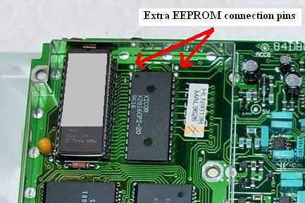
A standard HLN9313A logic board
The 24-pin EEPROM chip socket is soldered into
the bottom 24 pins of a 28-pin EEPROM layout.
|
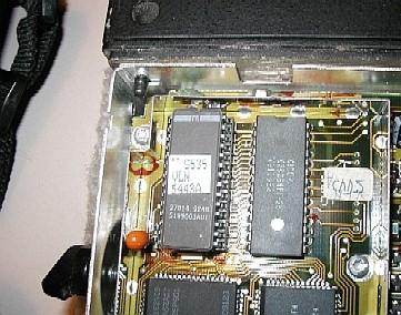
The special 99-channel logic board
A 28-pin EEPROM chip fills all the pins
|
The 99-channel RSS is also special - VVN4167A for 5.25 inch floppies or
VVN4168A for 3.5 inch floppies. Several people have tried swapping an Ontario
Hydro logic board into a high band or UHF radio and they claim that it does not
work. Apparently when the RSS was modified for 99 channels it was stripped
down to the 42-50 MHz range only. I've been told that someone could
just add additional entries to the MDF file for 99 channel VHF and UHF
radios, but I think it would take someone with an advanced debugging package
that could "look" into the 68HC11 CPU chip and the RSS and see where the
problems/limitations are before you could have a 99 channel high band or
UHF MaxTrac.
Many stock 42-50 MHz MaxTracs and Radius LRA radios have been
upgraded to the Ontario Hydro configuration - all it takes is a 42-50 MHz
radio with the standard HLN9313A logic board (the only one with the 16-pin
accessory connector), the special firmware, the special RSS, a 28-pin socket,
the larger EEPROM chip, and some time to swap the sockets, chips and move
two chip resistors on the bottom of the board (used as jumpers). The biggest
problem is locating the special firmware and the special RSS - everything
else is simple.
There's an article in this section on upgrading a standard 42-50 MHz MaxTrac
to an Ontario Hydro configuration. Couple that with the low-band MaxTrac to
Six Meter conversion article (in the MaxTrac section) and you would have
one very nice 60 watt dash mount 99-channel 46-54 MHz radio that could
cover the 47 MHz Red Cross channels, the 49 MHz National Guard
channels plus 6 Meter amateur radio (simplex and repeaters) all in one
box (something that would normally take a trunk mount MaraTrac or M400).
Just remember that low band mobile antennas only cover about 750 KHz (less
than one megahertz) without adjusting/retuning... you'd need a
screwdriver-type antenna if you wanted to actually cover even 1/4 of the range
of the 46-54 MHz radio while mobile. And there aren't many screwdriver
antenna controls that actually measure the frequency of the transmitter and
adjust the antenna... most (like Kenwood and Icom) get the frequency info from
the radio via a proprietary data link.
And if anyone has modified a HLN9313 logic board and then patched the
RSS to support a 99 channel configuration on high band or UHF (it should
be possible) and would like to do an article then let us know - even
anonymously. WA6ILQ has received more than one CD in the snail-mail with a
note saying "for repeater-builder" and no return address on the envelope.
Narrowband:
The GM300 radio was offered in factory wideband and narrowband models.
Occasionally it was necessary for a service shop to convert an RF board.
Due to this situation Moto parts made up narrowband conversion kits for the
GM300 / M10 / M120 / M130 mobiles. The parts
kit numbers are HLN9575 for VHF and HLN9576 for UHF. The price list note
says "UHF 12.5K CONVERS/MOBILE" and "VHF 12.5K CONVERS/MOBILE". Both of
the kits are about $80 (2007 price).
From an email to repeater-builder:
These conversion kits can be used on limited versions of the Radius
M100 / M200 and the MaxTrac mobile radios.
Kit HLN9575 is for VHF RF boards and they must be HLD4321C or later
(136-162 MHz) and HLD4322C (146-174 MHz) or later.
Kit HLE9576 is for UHF RF boards and must be HLE9310B (449-470 MHz)
or later.
The kit contains all surface mount components and this is why the
kit is limited to the later (surface mount) RF boards. The kit contains
the narrow IF filters as well as some caps and resistors and some
instructions. The instructions that comes with the kit was scanned and
is here.
The UHF kit documentation errors in that it mentions a limited number
of frequency ranges - it would lead you to believe that the GM300 series
radios do not operate in the 403-433 MHz range and the
GM300 465-495 MHz and 490-520 MHz models do not
exist, despite the fact that lots and lots of radios were built in those ranges.
Note that if you convert a radio to narrowband it is not
switchable - it's either wide (with the original parts)
or narrow (with the new parts).
One major thing to remember is that the radio won't program on
the new "in between" narrowband frequencies since the kit only
narrows up the receiver IF amplifier, compensates for the lower level
of receiver audio recovery and reshapes the exciter modulation. The
synthesizer step does not change, so the newly narrowbanded radios
will not do the "in between" channels. The modified radio is useful
only on the channels it would program on before and the lack of the
smaller synthesizer step will be an issue if you expect to be able
to progran the new "in between" frequencies into your radio.
Remember to readjust the transmitter modulation level and receiver
squelch settings after you install the kit!
There is some disagreement as to if the radio will be type accepted
for narrowband service after the mod is done. No type acceptance sticker
is provided with the kit. Note that the MaxTrac and Radius model numbers
do not have a narrowband option, only the GM300 series model numbers do
(the seventh character is a "2" for factory wideband, a "0" for factory
narrowband). For example, the M44GMC20D3AA is a wideband radio, the
M44GMC00D3AA is the same radio in narrowband.
Please do the next guy that works on the radio a big favor - put
a note inside the radio chassis that says that the radio has been
narrowbanded with the (part number) kit, and the date. And put the
note inside the radio, NOT scotch taped on the inside of the
lid / shell / cover... I've seen them end
up on the wrong radio.
Note that the GR1225 is the wide/narrow replacement for the GR300,
and there is an upgrade kit for the GR400 rack-mount and GR500 wall
mount packaged repeaters that replaces the two GM300s with one
R1225 full duplex radio module that is programmable wide or narow
on a per channel basis. For more info on the R1225 (including PDF'd
manuals)see the web page here.
Personal opinions:
I've not looked at the schematics in detail, but I suspect that you
could take the parts list from the narrowband kit information above and
acquire the similar through-hole parts and with them you could narrowband
the older RF boards. Such a kit would work on the MaxTrac as well
as the Radius LRA M100 / M2xx series since once you get
past the through hole vs. surface mount issue from the
wideband / narrowband aspect the RF boards are esentially
the same between the GM300, MaxTrac and the Radius LRA. I also think
the kits will work on the Maratrac since the receiver / exciter
is basically the guts of a 5-pin MaxTrac mounted in the Maratrac chassis.
Programming and the Radio Service Software
(RSS):
No matter if you have a MaxTrac, Radius or GM300 family radio, or
which band radio you have, the synthesizer is controlled by the radio's
internal microprocessor whose operation is controlled by the
codeplug (a block of binary data) which is generated with the Radio Service
Software (RSS) and loaded into the radio through the microphone jack.
The programming cable connects the microphone jack to the Radio Interface Box
(RIB) and that connects to the programming computer (PC). The computer is
running the Radio Service Software (RSS).
To do any reprogramming of the radios you need the correct
RSS, a RIB, the appropriate cables, and a slow PC with a real serial port.
These days you can replace the RIB and it's cables with a single RKN4081 cable
that has a 9-pin female "D" connector on the computer end and an RJ-45 plug
on the radio end.
The MaxTrac was designed in the days when the average user had a 16
or 20 MHz 386 and the bleeding edge software development computers
were 25, 33, 50 or 66 MHz 486-based machines. The MaxTrac and Radius
RSS requires a real serial port as it bypasses the MS-DOS / PC-DOS
operating system and talks to the serial port hardware directly. The earlier versions
of Maxtrac RSS run only on slow computers as it uses software timing loops to
create critical delays (the last revisions of the RSS are less sensitive to this than the
earlier ones). You must have an appropriate older computer booted into pure
MS-DOS or PC-DOS (version 5 or later) and this does NOT mean a
DOS window in any version of Windows!!! If RSS, the RIB or DOS is a new
topic to you I suggest that you see the Motorola RSS and RIB page at this web
site. There are more details including some "old computer" notes there.
Update 2022: There is a freely downloadable software package called
"DOSbox-X" that will run GM300 RSS and do it sucessfully. Just configure it
to emulate a 233 MHz Pentium II. It's unknown if it will run Maxtrac
RSS. If anyone has please contact WA6ILQ with the DOSbox-X configuration
parameters you used and he'll update this paragraph.
The MaxTrac, Radius and GM300 series are programmable radios
as opposed to crystal based. Their internal processor runs a program
that is contained in either the CPU chip or in a Programmable Read-Only
Memory (PROM) chip (referred to as firmware). If you are going to be doing
any upgrading, or you are converting a trunking radio to conventional, you
will need a PROM-based radio (which leaves out the HLN9123 low-end 5-pin
logic board) and a 27C256 PROM chip programmed with the correct firmware
image. you will need to look at the model number table to determine
which radios have the expanded logic board. And if you take a logic board
from a cheap 800 MHz eBay radio it is most likely going to have
trunking firmware, so you will need a replacement conventional firmware
chip anyway (or a firmware chip image file if you plan on erasing and
reburning the existing chip).
Speaking of trunking, if you find a firmware chip in a radio that
has the name "Scholer-Johnson", "SJI", "CVT-2-400", "ver. 2.14",
or any combination thereof then you have one of the radios that
was converted to LTR trunking (usually 800 MHz, but occasionally
seen on UHF or high band). To convert it back to a regular radio
you need the stock conventional firmware, and then you get
to blank and reinitialize the logic board. Occasionally you find
the stock firmware in an antistatic wrapper stuck inside the radio
but that is extremely rare. If you want to do anything with a SJ
trunked radio (even just to reprogram the frequencies) then you
need the Scholer-Johnson-authored RSS to talk to it. If you don't
have it then all you can do is to swap firmware and do a full
realignment from scratch (since without it you can't read and
save the tuning data before you blank the board).
If anyone is familiar with the SJ-equipped trunking radios and
would like to write a SJ-to-regular conversion article, we'd
love to have it. Just contact WA6ILQ. And he'd love to acquire
a 465-490 Scholer-Johnson GM300 (and the RSS).
The last MaxTrac conventional firmware (version 5.34) is available
from Motorola at the time of this writing as part number HLN5569A and
it supports the max channel count in a low band, high band or UHF
radio. The 900 MHz conventional radio uses a different logic board,
and uses different firmware - it's FVN4019A version 30.03 (or later).
The last pricing on either part number had was about $25. There have
been reports that Moto is no longer selling firmware chips and people
have had to acquire them elsewhere. More notes on firmware, including a
list of 10 different part numbers, is in the "Introduction to..." article
in this section.
If you need a PROM / EPROM programmer I've used
the Pocket Programmer and never had a problem. The original ones used
the parallel port, the newer ones are USB.
Disclaimer: I'm not related to that company in any way, I'm just a very
satisfied customer.
The MaxTrac-specific RSS is part number RVN4019 (on 5.25 inch floppy disks),
or RVN4020 (on 3.5 inch floppies). Neither will work on the MaxTrac LS
(trunking) models. Later versions were offered on 3.5 inch disks only. The
most recent (and last) version was used in preparation of the articles in this
section. It is Moto part number RVN4019K which identifies itslef on the startup
screen as Revision R07.02.00a, and dated 25-Jun-97. This version is known to
work on Pentium processors as fast as 800 MHz. The Maxtrac RSS Manual is 68P80900Z03-J
and we'd love to have a PDF of it. The author uses a Panasonic CF-27 laptop
for MS-DOS radio programming and a CF-30 for Windows 7 (32-bit).
The Panasonic CF-series have a hardware serial port. That is important as
soem of the USB based serial adapters hasve problems.
The Radius M100, M206, M208, M214, M216, and VR100 radios use a different
RSS, model HVN9173H, version R08.00.00 dated 05-May-1993, commonly called
RADMBL (short for Radius Mobile). It was available on 3.5 inch media only.
The GM300 series, which include the M10, M120, M130 and GM300 mobiles
(which are the radios in the GR300 desktop and GR400 and GR500 packaged
repeaters) use RSS HVN8177. As of this writing the current version
is R05.00.00, dated 01-OCT-94. This RSS is only available on 3.5 inch
diskettes.
A DeskTrac is a tabletop station that was shipped containing either one
(a base) or two (an intermittent duty repeater) MaxTrac mobile radio chassis
and uses RVN4079, which also has the MaxTrac software as part of it (either
RVN4019 or RVN4020). Yes, the DeskTrac RSS package contains two separate RSS
packages, one for the radios and the other for the control board.
But look inside the case before you go looking for RSS - I've seen surplus
DeskTrac cases with Radius LRA and GM300 radios in them!
Note that the white plastic case that was designed for the DeskTrac was also
used for the Spectra series radios under a different marketing name. The Spectra
Consolette (desktop station) is covered on the Spectra page at this web site.
Since the stock DeskTrac uses MaxTrac radio(s) the MaxTrac section of
the ebay warning notes above regarding operation below 449 MHz applies
to the DeskTrac as well (unless you put a 438-470 MHz GM300 in it...
but the channel display goes nuts as the data format is different).
More DeskTrac notes are in the text below.
To do any logic board swapping in a MaxTrac you will need the MaxTrac Lab
RSS, a totally different package. And there are at least two different
versions of the Lab software "out there".
The RSS reads the radio and looks up the model number in an internal table
that "knows" what the band limits are. Programming any frequencies outside the
preprogrammed limits requires using the "Shift" trick or patching the limits
in the RSS (i.e. hex editing the RSS file). Operation outside the firmware-imposed
band limits will result in the power control and deviation control functions
in the radios going totally berserk - one of the most common results is that
the transmitter goes to full uncontrolled power output - I have seen a 60 watt
low band MaxTrac put out 109 watts... and you couldn't turn it down. The
frequency range was 42-50 MHz and the owner was trying to program
Red Cross frequencies in the range of 47.40 MHz to 47.550 MHz
as well as 6 meter amateur frequencies near 52 MHz and 53 MHz.
Below 50.00 MHz the power control functions worked just as they should,
above that the radio was uncontrollable. There is an article by Bob Meister
WA1MIK on the MaxTrac page describing the fix to this problem - and the
fix applies to all bands.
The transmitter deviation level is also controlled by the RSS and the
radios microprocessor. The total deviation level can also go a little crazy
when the radio is programmed outside the limits. Bob has another article on
getting the 900 MHz MaxTrac to fully cover 902-928 MHz and the
deviation fix is in that article. While the article is written for the
900 MHz radio the circuitry used in the deviation fix applies to
all bands.
It's interesting but Moto's RSS software can do things the radio can't - so
make sure you don't have the same function (i.e. PL decode out, COS out, etc.)
programmed for more than one pin on the accessory connector at the same time.
While the RSS will let you do it (the programmer forgot to check for that),
the radio doesn't work right if you do... And the symptoms are not what you
would expect... So in your programming procedure add a step right before
you write to the radio: if you've changed any of the I/O pins go through
them one by one, and make sure that no function is duplicated. The radio
will do strange things if any are.
People missed this when I had it in standard sized font, so...
On any radio that is new to you you need to download the existing
codeplug (the existing frequency, tone and radio-wide data) and
archive it. It's better to have a backup and never need it
than to need it and not have it.
Before you reprogram your new radio you need to TEST the radio on
it's original frequencies BEFORE you do anything to it. Make sure the
receiver receives properly, and the transmitter makes proper power
and modulates correctly. You don't want to reprogram it or modify
it and discover it has problems and only then realize you don't know
if the radio was good to start with.
On any radio that is new to you do NOT assume that any accessory
connector pin programming is present, or if it is there, is correct
for your radio environment.
Always plan on reprogramming any newly acquired radio to
meet your own requirements.
When you acquire your MaxTrac or Radius radio remember to
download and save the original (i.e. commercial frequencies) code plug
(for one thing, it contains the tuning information). If you screw something
up you will want to be able to backstep to something that is known to be
good. If you have access to Lab software make a second backup using
that as the Lab backup copies a lot more data to the saved file. And
remember, a floppy disk is NOT a good long term archival medium. Hard drive
space is CHEAP. Personally I copy any code plug that I want to archive to
an archive directory on my hard drive, using both regular and Lab software
(each to a different disk file), and that archive set gets copied to a USB
backup hard drive and two different CD-RWs. More details are on the
RSS / RIB pages at this web site.
Final note: If you have problems programming a radio, and nothing
seems to work, open it up and look at the part number of the logic
board and the RF board, then compare that to the radio model charts.
You may find that the model number tag on the PA heat sink is wrong!
From a posting a while back on the repeater-builder mailing list:
I have found out that my radio is NOT a MaxTrac M100 as the model
number tag on it says. It is actually a Radius M216 with a MaxTrac
M100 PA and tag on the back. Apparently someone along the line had
swapped the original PA with one from an M100.
So his MaxTrac M100 is actually a Radius in MaxTrac clothing. He had
to use Radius "RADMBL" RSS to program it. And this is not
a unique situation, I have seen a GM300 front plastic mated to a VHF
Radius LRA radio and in another situation a GM300 front plastic
was on a 900 MHz MaxTrac. And I've seen a GM300 PA bolted to
the back of a Maxtrac.
Limitations:
Above all, remember that the MaxTrac, M-series, Radius LRA
series and GM300 are MOBILE radios, made with minimal heat sinks, and
while they can be used quite readily as a low-to-medium performance
repeater receiver, or as a link receiver, you can NOT use it
as a repeater transmitter, as a link transmitter or as an IRLP node
radio without due consideration to the normal mobile radio limitations
on RF power and duty cycle.
Remember that the beauty of a repeater is that it is a device that
allows one-to-many communications rather than a cellphone, which is
limited to one-to-one. As such, while any individual user may only
transmit for 10 to 30 or even 60 seconds the repeater is transmitting
for the duration of the transmissions of all of the users continuously
one after the other. And if it's an IRLP-linked repeater then the
user count - and transmit time - just increased to add all the users
on the other end of the link or reflector.
As a 10% to 15% duty cycle radio the MaxTrac, Radius and GM300
(and the GR series repeaters that were made from them) are designed
to transmit for no more than 10 to 15 seconds out of each 100
seconds. This is not to say that you can't transmit for three
minutes, but the transmitter is going to get hot, and the longer it
talks the hotter the mobile radio gets. These radios were designed
for a 10% to 15% transmit duty cycle, and the internal power control
circuitry is the only thing preventing the radio from burning itself
up.
The MaxTrac and Radius radios have power control circuitry that
turns the transmitter power down if you talk too long (all it does
is measure PTT time), where the GM300 series radios actually measure
the PA deck temperature with a thermistor (hence they "know" if there
is a fan present or not). Due to the timer design the MaxTrac and
Radius radios assume that there is no fan.
The MaxTrac and Radius power control timer can create a situation
where the transmitter goes into power shutdown on its own, which can
happen in the middle of a conversation. This WILL happen in
a long transmit situation.
The radio might not be hot (due to a strategically placed fan), but
the microprocessor "knows" it has to be, and steps the transmitter
power down to zero. It'll recover for a few minutes after it's unkeyed,
then do it all over again until it has adequate time to rest. You
really don't want your repeater fading out during something important
like a search and rescue operation, or even a 911 autopatch call.
The article on Manual Power Control (in this section) shows how to
address this problem by bypassing the shutdown control. Just make
sure you have a suitable external temperature control system in
place (fans, etc). And it would still be a good idea to put a
thermal snap-action switch on the heat sink and use it to trigger
a backup fan - and maybe a repeater controller announcement.
Despite these comments, if you ARE going to use one then pick
a 03 / 04 (the 1-10 watt radios) or 33 / 34 series (the 10-25 watt
radios) radios as it is a better choice than a 43 or 44 series
(the 25-45 watt radios).
In short, with very, very few exceptions, any mobile radio
(Motorola or otherwise) used as a link or repeater transmitter is
a recipe for failure, especially if the system includes
EchoLink or IRLP... as I said above, the repeater is transmitting
for the entire conversation of all the users, one after the other,
however with a linked system the user pool now includes everybody
on the local system plus everybody on the far end node, or if
connected to a reflector then every person on every node that is
connected to the reflector.
I've seen a photo of a 110w Spectra trunk mount mobile where
the power control failed and let the transmiter run at full blast
for as long as PTT was held down. Then one day the driver sat on
the microphone for an hour during a road trip. The transmitter PA
burned itself up and the radio was not economically repairable
(which is why you enable the idiot timer into any mobile radio
that has one and set it for 30 seconds or 1 minute).
The "Executive Summary": If you are going to put up a repeater
(or a point-to-point link that will have a similar duty cycle), don't
use a low-end low duty cycle mobile radio (from any manufacturer)
as the transmitter. It's one thing to use a mobile radio based
repeater like a GR300 (or similar) in a shopping mall environment
to talk to the rent‑a‑cops or to tell housekeeping to
clean up little Johnny's spilled ice cream cone, but you want
something with a higher duty cycle as your primary area repeater.
These radios were designed for a range of RF power - for example,
the D04 (or M04) series is a 1-10 watt radio, a D34/M34 is a 10-25
watt radio, and a D44/M44 series is a 25-45 watt radio. 25 to 45
means not more than 45, but also not less than 25. If you run outside
that range, it will be inefficient and run hot. Yes, strange
as it may sound, a D44 run at 15 watts runs hotter than when run
at 30 watts.
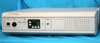
Even this DeskTrac tabletop base (which has a MaxTrac inside and
also came in a repeater version with two MaxTrac radios inside)
has the MOBILE limitations.
Using an external power amplifier:
If you want to use one of these radios to drive an external power amplifier,
look for a D03 or M03 (VHF) or a D04 or M04 (UHF) radio. Those are specifically
designed as 1-10 watt radios and can be adjusted to anything in that range.
5 watts is plenty to drive an external amplifier to whatever power level you
can afford. The author maintains a number of commercial repeaters made from dual
M04GMCs (one for the receiver and the second as the exciter with a fan on the PA)
running 4-5 watts driving continuous duty 100 watt Henry Electronics
amplifiers backed down to 60, 90 or 100 watts (depending on the license). They have
been in service since the mid 1990s with very few problems.
If you have a MaxTrac, Radius LRA or GM300 series radio with a dead
PA deck then you can use the exciter output directly into an amplifier that
is designed for that power level. The exciter output (from the RF board) on
MaxTracs, Radiuses, and GM300s is anywhere from 20 to 50 milliWatts,
depending on the operating band (220 milliWatts on 900 MHz).
The schematic diagrams show signal levels of +13dBm to +17dBm for various
VHF/UHF/800 MHz radios (that's 20-50mW), but +23.5dBm for the 900 MHz
models (there's where you get 220mW). These power levels have been confirmed by
actual measurement. The exciter output connector on the RF board is a female
Taiko-Denki connector. The male connector require a unique crimping tool to be
installed properly, and they are designed to fit only a few types of coaxial
cable. https://rfconnection.com/ will
make custom cables with T-D connectors for very reasonable prices. So get a
jumper with a T-D on one end, and a single-hole female BNC on the other and you
are good to go.
Initial Checkout, Repair, Tools, and Hardware Oddities:
(This section covers the mobile radios - see the DeskTrac Overview article
in this section for additional information on the tabletop station.)
CAUTION: DON'T
LET THE SMOKE OUT !
The Motorola mobile radio products made prior to the Maxtrac mostly used push-pull
audio power amplifiers and audio output transformers, and drove
the speakers as a hot wire to ground. The MaxTrac, Radus, GM300 and
many later radios eliminated the audio transformer and they run the
the speaker as the push-pull load directly... this means both sides of
the speaker are floating above ground. This quirk is significant on
your workbench: any audio test equipment that would normally connect
to the speaker (such as you would use to make a quieting measurement)
must be on the far side of a audio isolation transformer. Motorola has
a low-power one as part number SLN6435 in their test equipment catalog
(being "test equipment", it's high priced - at about $80 in 2006), and they
also include a cheaper but higher audio power one in every tabletop
base station (part number 2580188B01, about $35 in 2006) since common
wireline remote controls expect ground-referenced audio to drive the
remote sepakers.
In a pinch you can connect a 2 watt resistor of any value from 8 to 22 ohms
to the radio as a speaker load, and use a 600 ohm to 600 ohm line transformer
between the radio and the test equipment. I've had good luck with 600 Ohm-to-600
Ohm transformer (like a Triad TY145 - available from Mouser Electronics
(p/n:553-TY145P) under $4 as I write this). Note that the audio bandpass
characteristics of whatever isolation transformer you use will have to be
wider than the audio frequencies you hope to pass through the radio.
The Triad TY145 is a broadband audio transformer and if you use that one
you won't have to worry about that.
In short, if you ground one of the speaker leads the odds are better
than 75-25 that you will let some of the magic smoke out of your
radio. So use an audio isolation transformer to prevent
this - just put the transformer between the radio and any load that
isn't a floating (an ungrounded) stand-alone speaker.
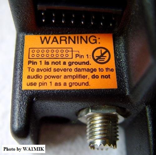
Some radios have this sticker, some don't. Believe it and heed it.
Run all MaxTrac, Radius LRA and GM300 radios with ungrounded (floating)
speakers.
The radios that have a 16-pin accessory connector DO NOT have the
internal speaker connected by default - it takes a jumper plug to
enable it. More details (including a photo) will be found in other
articles.
You will need T8, T10 and T15 Torx™ screwdrivers to open and work
on the radios. Torx head fasteners are getting more and more common in the
automotive world and most tool stores, even Home Depot, Wal-Mart
and Harbor Freight now carry the screwdrivers and bits. Note that the
T8 is less common in the prepackaged kits... I've seen a number of
bubble-packed kits that started at T10 and went up in size so you may
need to hunt a little for a set that includes the T8 size. Personally
I avoid the sets with a single handle and changeable bits as my primary
bench tools - it seems that you spend as much time changing bits as
working on the radio. And after a while the bits get loose in the handle
and won't stay put, so you spend more time looking for the dropped bits
on the floor (or wedging a piece of paper or foil into the handle to keep
the bit in place).
To open the radios you will need to remove the two screws from the
control panel (T15) and the four flat-head screws from the sides (T10).
Pull the control panel outwards from the front of the radio just a little
to free up the top and bottom covers, then pry the covers off. They
are identical and split in the middle of each side. Sometimes they're
hard to get apart, but nothing else holds them together. Usually you
can get them going by using a flat blade screwdriver and starting in
the front where the edge is exposed over the metal chassis. If you
need to remove the logic board you will need a T8 screwdriver to
remove the small flat-head screws that hold the logic board's
heatsink to the side of the chassis.
If you acquire a radio and don't know it's history, as
you do the initial bench check you will want to check it for
frequency accuracy - and test both the receiver and the
transmitter separately. First check to make sure all the
screws that hold the boards in place are tight. If they
are at all loose you will have an unstable and / or
microphonic radio. If you find a stripped hole then you will
have to use a larger diameter screw. Personally I install a
HeliCoil™ to salvage the threaded hole. Or you can
relegate that radio to the "to be cannibalized" shelf (i.e.
use it for spare parts). I've a number of "frankenstein"
radios in service (built up from spare parts).
If your new-to-you GM300 family radio is off-frequency AND it
is shock / vibration sensitive you will find that in
many cases if you clean the pins and jack between the boards very
well the problem goes away. Once the pins are clean a microdrop of
a product called "Stabilant-22" (also known as "Tweek") on each
pin helps a lot. The 15 mL bottle size is carried by Motorola
Parts as part number 1180369E78.
If the entire radio is waaaay off frequency (both transmitter
and receiver) and cleaning the pins doesn't help AND it is NOT
vibration sensitive... well, this is very rare these days, but
does show up once in a while...
The RSS contains a "warp" adjustment to bring the reference oscillator
(the main frequency determining circuit in the radio) back on channel,
but Motorola had a bad batch of the 14.4 MHz reference oscillator
crystals that drifted beyond the ability of the warp adjustment. The
story that I heard from two independent sources is that the
offshore crystal manufacturer tried to cut one too many corners
and didn't fill the crystal cases with dry nitrogen during manufacture,
but nobody knows for sure (or if they do, they aren't talking). The
crystals passed receiving inspection, were assembled into radios and
shipped to customers. Within a year or two they had drifted to the
point of being almost unusable. Any surplus MaxTrac is old enough now
that any bad crystal has probably already been changed out by the time
it is in an amateur radio operators hands, but you occasionally find one
that has been a shelf spare all its life. While a crystal house like
International, Bomar or JAN is one source for a replacement, Motorola
Parts is cheaper in this case (and since it's a stock item you won't
have to wait for it). The part number for the 14.4 MHz crystal is
4880174D05 (when you get it don't be surprised if it's labeled "14400.00",
"14400", or "14.4"). The part number is the same in the MaxTrac, Radius and
GM300 series and it will set you back around US$14. In the GM300 manual Moto
says this crystal is not field replaceable but it obviously was in the days
of the mass swapout under warranty (supposedly Moto was shipping out thousands
of replacement crystals per month for several months). There is a paper tag
glued to the side of the factory crystal with an 8-digit number that contains
the temperature coefficient information that needs to be typed into the RSS
(see this photo), and naturally
a new crystal will be different than the old one, but the data on the label
on your old crystal should be a good starting point. See the paragraph
titled "Reference Oscillator Coarse Adjustment Procedure" on the GM300
info page in this section.
If the transmitter is on frequency then the main crystal is fine.
If just the receiver is off frequency (or seems dead) then you will need to
check the frequency of the second oscillator crystal. The VHF high band,
UHF, and 800 MHz MaxTracs and Radiuses use a 44.645 MHz, crystal,
part number 4880008K02, which has been replaced with 4880606B02 for about
$20US as of August 2008. If you have a M10, M120, M130 or GM300s look
carefully at the old crystal before you order the replacement as some used
the 44.645 MHz crystal and some used a 44.845 MHz crystal (part
number 4880908W04). The VHF low band radio uses the same 14.4 MHz
master oscillator but it uses a 10.245 MHz crystal (part number
4880908W01). The 900 MHz MaxTrac uses the same 14.4 MHz master
oscillator but it uses a 38.695 MHz crystal (part number 4808005K21)
that no other model uses. Again, in each case the "real" Moto part is
probably the cheapest (and since it's a stock item you won't have to wait
for it).
There is one exception to the "off frequency" info above. If you have
a trunking 900 MHz MaxTrac that has been converted to conventional,
and it is about 12.5 kHz off frequency, check the firmware chip
part number ! For example, if it's programmed to 927.5000
and you find it transmitting on or near 927.4875 or 927.5125 (and it's
consistently off the same amount across the band) that's the second thing
you check (the first, as mentioned above, is the pins that connect the
two boards). The 900 MHz radios use unique firmware and having a
VHF / UHF / 800 MHz chip in a 900 MHz radio
will cause multiple problems, but the most visible and easiest to check
is that its off frequency ! DO NOT just "make do" and program
the radio 12.5 KHz off so that it lands on your target frequency, use the
correct firmware ! The off-frequency problem is just the most
visible of the problems you will have with using
VHF / UHF / 800 MHz firmware in a
900 MHz radio.
If you are not going to be using the accessory connector in the radio
(i.e. you will be using it as a mobile) then you can ignore the next
paragraph. On the other hand, if you are going to be using it as a link
receiver, as a control receiver, or as an IRLP or Allstar radio, then you
need to pay attention.
There is a 3-pin jumper on the logic / audio board of all the
MaxTrac, Radius and GM300 radios that selects the mode of pin 11 in the
accessory connector of all the non-900 MHz radios. A shorting jumper
selects the "A" position or the "B" position. Note that this jumper does
not affect the speaker audio, it only affects this one pin in the accessory
connector. In the "A" position the pin is fed a constant level of un-muted
flat audio (i.e. not de-emphasized). In the "B" position (the factory
default) the pin is fed a constant level of squelch-muted normal audio
(i.e. de-emphasized) which makes it ideal as a source of receiver audio
for feeding to a port on a repeater controller, or to an IRLP or Allstar
interface. Needless to say, unless you specifically want flat un-muted
audio you want this jumper in position "B". So the first time you have any
new-to-you radio open for the first time you will want to verify the
setting of this jumper (and in reality, all of the jumpers).
Some other notes on 900 MHz MaxTrac and Radius LRA radios...
Courtesy of Greg Stahlman KJ6KO:
The 900 MHz MaxTrac logic board is unique and has several differences
from the low band, high band and UHF ones, two of which are important to those
of us that use them in repeaters:
First, unlike the low band, high band and UHF radios the JU551 jumper on the
logic board HAS NO EFFECT on the de-emphasis of the audio that feeds pin 11
on the accessory jack! This is because the 900 MHz radio has different
audio pathing and the de-emphasis is done in the "HEARCLEAR" circuitry on the
microphone connector / HEARCLEAR board. JU551 will only select
between raw discriminator audio and squelched, high-pass-filtered (PL Filtered)
receive audio. The pin 11 audio will NOT be de-emphasized either way! If
you want de-emphasized receiver audio, you need to pull it from pin 8 on the
microphone jack. If you want de-emphasized receiver audio on the 16 pin
accessory connector you need to remove the JU 661 bumper block and add
a jumper wire internally from the center pin of JU 551 to pin 8
on the microphone jack.
Second, the microphone input (pin 2) on the 16 pin accessory connector is
NOT pre-emphasized! Again, this is done in the HEARCLEAR circuitry on the
microphone connector / HEARCLEAR board. If you want normal
(pre-emphasized) transmit audio, you must use the microphone jack on the
front of the radio, perhaps with a DC-blocking capacitor in line (+ side
towards the radio). The rear connector does work, but it delivers
non-pre-emphasized (flat) audio to the transmitter.
Another reader provided this information:
On 900 MHz and higher the feedline needs a lot more attention than
on the UHF and lower frequencies. Personally, I prefer to use the kits designed
by Moto for 800 and 900 MHz that use the white Teflon (both dielectric and
jacket) low loss coax for any 800, 900 and 1200 MHz mobile antennas. Moto
has a nice kit of the NMO mount and 14 feet of coax kit - part #0180351A78 at
around $24 each (as of Feb 2011). The coax uses a stranded center conductor
(which is A Good Thing when you are mounting the NMO mount on a vehicle trunk
lid... in fact there is no excuse to use solid center conductor coax for any
mobile installations).
More details on the internal jumpers in these articles:
Cosmetic parts: (including
the speaker)
If the MaxTrac / Radius volume control knob is missing, you need to
order out part number 3680144M01 (or 3680106M03 for the GM300 series),
the MaxTrac 2-channel conventional escutcheon (faceplate) is 1380276L02,
the MaxTrac multiple-channel conventional escutcheon is 1380277L01,
the accessory connector gasket is 3280014N03, a replacement plastic
case half for any of the MaxTrac, Radius LRA or GM300 series radios
(the top and bottom is identical) is 1580127L01.
I've seen MaxTrac, Radius LRA and GM300 family mobiles mounted vertically
on truck dashboards (i.e. with the front panel horizontal and facing up).
In that situation the the speaker grille area seems to be a magnet for
coffee cups and soda cans. If the internal speaker in your
new-to-you radio is buzzy or raspy you might want to check the speaker
cone - in fact the entire internals of the radio - for
coffee or soft drink residue. Sometimes you find that the internal
speaker is electrically open. If you decide to replace the speaker,
for whatever reason, a new internal speaker was part number 5080085D02 or
D03 (depending on which book you read), both of which have been replaced
by p/n 5004639J01 that will run you around US$7 (as of early 2009); of
course both are NLA in 2017. An alternate speaker, one with integral
mounting flanges, is 5080496Z01 and it too is NLA from Motorola, but you will
find some of the J01 and Z01 speakers on a popular auction site. BTW,
the stock internal speaker is a 22 ohm, 5 watt device. If
you are running a MaxTrac, Radius LRA or GM300 as a mobile in a noisy
vehicle you will tend to run the volume up loud. Well, the tiny
internal speaker gets real distorted real quick as you crank up the
volume. In those cases you really will want an external speaker - and
the one made for the MICOR or Syntor speaker is an excellent choice. Likewise
if you are running a MaxTrac, Radius LRA or GM300 as a base station in a noisy
office you will find that an external speaker makes a world of difference.
More speaker notes, including model numbers for the better external
speakers are below.
If you need to you can purchase a complete new plastic front panel from
Motorola for about US$35 and its part number is HCN3217B. It comes minus
the escutcheon, that's the flat plate that surrounds the buttons and labels
their functions. Or you can scavenge a front panel from an 800 MHz MaxTrac,
which are common and cheap, and install a new escutcheon so the buttons are
labeled properly. The six channel radios commonly have the scan button
labeled as Exit, so if you want a new full feature escutcheon as I said
above it is part number is 1380277L01.
Replacing the Antenna Connector in the radio: (with
some notes on the DC power connector) (hint: don't do it
unless you really have to)
The chassis-mount coax connector on the back of a MaxTrac, Radius LRA mobile,
and GM300 is called a "Mini UHF" female connector and in many cases these
radios are the first time that some people have seen this connector. The
female connector Motorola part number is 0980131M01. They cost about $6 each and
come in bags of 5. This part IS still a currently available part because it's used
on so many Motorola products. Even the Quantar uses one. The Motorola part number for
the male connector is 2880376E84 and this part number is a crimp-on connector
for RG-58 sized cable. There is a Mini UHF male to full size UHF Female
adapter available as part number HKN9557A. Several antenna manufacturers
sell kits that include the mini-UHF male connector already mounted on the antenna
cable. There are a wide variety of test adapters available from
RF
Industries.
Do not use an adapter to connect a RG213 or RG-8 sized cable to the mini-UHF
connector on the back of the radio - you cna break the adapter or the connector.
Use a pigtail cable with a mini-UHF male to a "N" or SO-239 female.
Sometimes the chassis mount female coax connector on the radio needs
replacing... I've seen several with a damaged center pin that makes
intermittent contact with the coax center pin, and I've seen one that was
really mangled to where you could not screw the male connector on it.
Often the little "teeth", (that keep the plug from rotating when tight) get worn off.
The problem is that replacing it is a lot more work than you would expect due to
the way the radio was designed and put together (the antenna connector is soldered
to the bottom of the RF amplifier board, which is a major pain to remove), so don't
proceed unless you really have to. If the only problem you have is worn teeth
and the antenna cable connector becomes loose on its own try slipping a tiny O-ring
on the center pin of the plug, then tightening the connector enough to compress the
O-ring about halfway. The increased friction will prevent the antenna connector
from coming loose. Note that this trick is only a stopgap, you WILL have to replace
the connector eventually, but it can buy you several years in a base station
environment. By the way, this same trick (with a larger diameter o-ring)
works on full size PL-259s (it's a very common trick used on CB radios installed in
the big 18-wheel trucks).
The antenna connector itself is rather easy to replace, but you must remove the
circuit board from the power amplifier to extract it. That also means you must
unsolder and remove the DC power connector from the circuit board first. This
is much more difficult than it initially seems. The connector leads are thick
and the circuit board holes are just barely big enough for them. The holes
in the PC board also have copper sleeves inside that connect both sides of the
circuit board together. These sleeves often come out when extracting the
power connector, requiring further work to fix the newly created damage.
So if you really have to change it, the large mass means that you need
to use a larger soldering iron, or even a soldering gun to heat each lead,
then remove as much solder as possible from the joint. I keep my late
father's old Weller 8100 soldering gun (purchased in 1958) in the bottom
of my tool box just for jobs this. Once the solder is out of the way
you can remove the power connector mounting screws (using a T10 screwdriver),
then pull on the connector as you alternately and quickly heat each lead at
the circuit board. Eventually you will be able to wiggle it out and
then you can do a better cleaning job on the leads and holes. Another
option is to chop the old power connector apart using a Dremel Moto-Tool
equipped with a rotary saw blade, then remove the individual pieces (if
you have decided to replace it then who cares if it comes out in one, two
or several pieces - minimizing the damage to the circuit board is much more
important).
Once the DC power connector has been extracted, you can remove the screws
holding the circuit board and RF components to the heat sink. The mini-UHF
antenna connector can now be unsoldered from the board, or you can remove its
mounting nut and remove it with the circuit board. It's probably better
to install the new RF connector into the heat-sink first, then clinch the nut
down TIGHT, then reinstall the circuit board, then solder the antenna jack.
Since the DC power connector is already loose on your bench, I'd take a
good look at it. If it's worn, damaged or mangled I'd seriously consider
replacing it. A new one is part number 0980255E01 and Moto parts price
(at the time of this writing - early 2006) is around $11 each. Yes,
it's a little steep, but the hard work of removing the old one IS already
done ...
Accessory Connector Notes:
Depending on the radio model it will have either a 5-pin or 16 pin
accessory connector. Most hams look for the 16-pin radios because
they are easier to interface to other equipment. That's fine as
it leaves the 5-pin radios for me, and adding a single resistor and a
single NPN transistor gets you a COR signal. Adding a DE-9 pigtail
cable is easy (see the article in this section). And 9 pins
are plenty to do everything I need to do... (including feeding power
into a receive-only radio and connecting it to bypass the power switch
on the volume control).
The radios with a 5-pin accessory connector have the internal
speaker on full-time, where the ones with a 16-pin connector enabled
it with a jumper on the accessory connector. This jumper
can be implemented in any one of several different ways:
1) an official MaxTrac jumper plug inserted in the back of the radio,
2) a soldered jumper wire inside the radio bridging the two pins together.
3) a PC style two-pin option jumper inserted in the back of the radio (not
recommended in a mobile environment, but just fine as a base radio, as a
link radio or as a control receiver in a rack),
4) and I've seen one radio where the previous owner simply bent the two pins
together (so they were touching) and then soldered them together. It required
replacing the entire accessory connector before you could insert a standard
accessory plug into the back of that particular radio.
To enable the internal speaker you will want to tie pins 15 and 16
together or connect an external speaker to pins 1 and 16. Note that
one side of the speaker in the MaxTrac and Radius LRA series radios
and both sides of the speaker in the later M10, M120, M130 or GM300 series
radios is / are hot, and grounding a hot wire (even momentarily)
will let the lifetime supply of magic smoke out. The MaxTrac and
Radius LRA series uses two inexpensive individual transistors as an
audio output stage, the GM300 series uses an expensive audio power module.
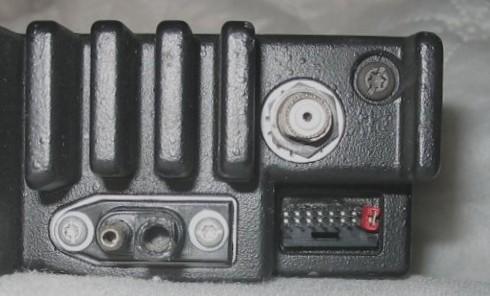
Above shows where to put the PC jumper - the rightmost two vertical pins.
By the way, the exposed power pin is the positive pin.
|
|
This is the pinout of the 16-pin accessory connector. See the
interfacing articles for a complete list of pin functions.
|
YOU CAN NOT USE THE ABOVE JUMPER TECHNIQUE ON MOST
FACTORY-PROGRAMMED RADIOS.
You will find that most radios are programmed for the alert / alarm
function when they land on the surplus market. The alert pin is grounded
when normal (i.e. not in alert mode) by a jumper from pins 7 and 9 and removing
the jumper (i.e. lifting the alert pin off of ground) causes the radio to transmit
the alarm signal. The PC jumper on the speaker pins shown above is only
usable on radios that have the alert function disabled in the programming of the
radio codeplug (which is one of the first things I do when I program a
new-to-me MaxTrac, Radius LRA or GM300 family radio). Just go into
the signaling menu and see if there is an MDC1200 system defined, and if so, set
its "Emergency Alarm" field to "None". More details can be found on the
Interfacing pages.
Note that the GTX radio uses the same 16-pin accessory connector, and it also
needs a speaker enable jumper plug... but the connector has a very different
pinout, which is covered on the GTX pages elsewhere on this web site.
DO NOT plug a GTX optioned jumper plug into a MaxTrac, Radius or GM300!!
YOU WILL DAMAGE THE RADIO as covered in
this warning
article - you will kill the audio output capacitor and 9 times out
of 10 the shorted cap will kill the MaxTrac speaker amplifier transistors or
the GM300 audio output module (which is expensive).
|
The plastic 16-pin accessory connector shell (the piece that plugs
into the radio) is DigiKey's part 104422-1-ND. At the time of
this writing DigiKey's price is about a US$1.50 each, or about US$1.25
each for quantity 25. AMP makes a wide variety of contacts for
this shell with varying wire sizes and plating types. The one most
appropriate for 22 AWG wire is DigiKey part number A3007-ND (AMP 1-87309-3)
at about 14 cents each (or about US$12.50 per hundred). And these
pins are gold plated! Mouser part numbers are 571-1044221 for the
connector (under US$2.00) and 571-1873093 for the pins (about US$0.20).
The pins snap into the connector body, and once in place are
designed to not come out (as you would expect). To remove
one you need the pin extraction tool, Moto part number 6680947W01,
which can be purchased by itself for about $2, but it is more
economical to buy the HLN9242A 16-pin Accessory Kit, which
includes this tool along with nine pre-terminated wires, a
connector body, and 16 extra (i.e.. loose) socket contacts. At
the time of this writing the HLN9242A kit costs about US$7.
Or if you have a piece of 0.020 inch steel shim stock around
you can make a pin extraction tool. Look on the "Keys Page"
elsewhere at this web site for a photo and the measurements.
Or if you are very careful you can use a tiny pick tool.
There's an instruction sheet that explains how to remove
the pins in the GM300 article in this section. Open that
article, scroll down to the Accessory Jack section and click on the
image that's there. It shows the extraction tool, and where
to insert it.
HINT: If you are just getting started I suggest you
buy a HLN9242A kit as you get a connector body, 16 loose pins,
9 pre-ended wires, and a pin removal tool. Then when you
need more plug bodies or pins just order them from DigiKey
or Mouser (both companies part numbers are in the interfacing
articles in this section).
Or... There is also the HLN9457A Hardware Kit (click
here for a photo) that
is specified for the GM300 but works just fine on the MaxTrac,
Radius LRA and CDM series... it has has 16 connector pins, five
wires that are eight inches long, with pins already crimped on
them however this kit is missing the tool. The price is in the
$5 to $6 range.
The GKN6271 is Moto's official ignition sense cable kit.
Replacing the Accessory Connector in
the radio: (hint: don't do it
unless you really, really have to)
Occasionally you run across a radio that needs a new 16-pin
accessory connector. Maybe one pin is bent, soldered to
another, or even broken off. The part number for the
16 pin right angle accessory connector is 2804503J01, at
around US$5.25 (early 2007 pricing). Like the microphone
jack, do not try and unsolder and remove all 16 pins of
the old jack !! It's dead anyway, just use a large
pair of diagonal cutters and chop apart the old connector. Once
all of the individual pins are free then unsolder each pin one
at a time from the bottom and lift each individual pin out of
the top of the board with a pair of needle nose pliers. When
all are removed clean out the holes with a solder sucker or a
round wooden toothpick. Now mount and solder the new connector.
I've never seen a radio with a 5-pin connector that needed replacing
but if you come across one the replacement part number is 0180747T09.
Speakers:
If the internal speaker is not loud enough, the standard Moto
mobile speaker with a 5-pin plug is part number HSN4019B, or the
same speaker with a 16-pin plug is HSN9326A (photo),
or you can take an old Motrac, Motran, MICOR, MASTR Pro or
MASTR II vintage swapmeet speaker and change the plug (just make
sure that both sides of the speaker are internally floating off of
ground). There are also amplified speakers that are part of
Motos "Power-Voice" line such as the HSN1000B (used in fire trucks,
and other noisy environments).
From an email from Jeff Kincaid W6JK:
The MaxTrac family radios have a built-in front panel speaker and sometimes
you will find a radio that has the jumper wire that connects the physical speaker
to the logic board missing (the radio was obviously used only with an external
speaker). A leftover lead from a PC case that has a 2-pin push-on connector
on one end will fit the speaker connector on the audio/logic board and substitute
temporarily - look in your PC parts box for a leftover front panel red or green
LED, or the wiring from a reset button. Just push the two-pin female plug
onto the MaxTrac logic board and cut the wires to length then solder the wires to
the speaker. At this point you will find that the case half won't go on because the
plastic body of the PC connector is too tall... been there... done that... The
quick and dirty solution is to remove the two female pins from the PC plug body,
put heat-shrink on them individually and push each one onto the logic board pins
(see this photo).
Note that they will vibrate loose in mobile service but this will get you by
in a base station environment or until you can locate the proper connector... some
PC sound cards use the actual 2-pin connector that Motorola used and you may find
one in someones junk box or at a PC repair shop.
According to the manual, the part number for the proper speaker lead assembly,
including the connector that plugs into the P10 speaker connector on the logic
board is 0180747T30 ("speaker cable assembly"). In mid-2002 it was about US$6.
Microphones, and Replacing the Microphone
Connector in the radio:
Occasionally you will find a radio with a bad microphone jack - perhaps
from wear, or perhaps from corrosion problems (green mold). Sometimes
it's not obvious until the RIB programming cable or the microphone does not
make contact or is making intermittent contact. Don't attempt to clean
it, you are just wasting your time (been there, done that several times). The
genuine Moto mike jack for all of the MaxTrac / Radius / GM300
series is part number 0980132M01, available for about US$4 from Motorola
Parts. Do not try and
unsolder all 8 pins and remove the old jack!! You don't want to risk
lifting the copper traces on the board (been there, done that, wasn't
pretty... was salvaging someone else's screwup). Just use a large pair
of diagonal cutters and chop apart the plastic body of the old jack (relax,
you are replacing the jack because it's dead anyway), then bend all of the
8 pins straight up away from the board, lifting out the pieces of the
plastic body as you go. Once the eight individual pins are free from
the plastic body and standing up in the breeze then unsolder each pin one at
a time (from the bottom of the board) and lift it out (with a pair of needle
nose pliers) from the top of the board. When all eight pins are removed
clean out the holes with a solder sucker, compressed air or a round wooden
toothpick. Now mount and solder the new jack.
Note that the base station and mobile microphones for the MaxTrac, Radius,
GM300 and several other radios (including the DeskTrac) look absolutely
identical, but may or may not be interchangeable because they can be wired
differently inside (the differences involve only the first two pins, see the
pinout table below).
So yes, any RJ-45 microphone can be plugged into any MaxTrac series radio, but
if the first two pins are wired different it may not work. Before you
purchase microphones that have a RJ-style plug on the microphone cord you need to
verify that the wiring is compatible. There is a table of known good
microphone part numbers below. If you have one that works but isn't on
the list, please let us know the model number so we can add it. Addtional
parts information is in the parts catalog PDFs available on the main index
page. Note that there are errors in these catalogs, so always check
with Motorola's Parts ID group before placing your new microphone orders. Since
pin 1 and pin 2 in the mobile microphone jacks are unused we take
advantage of that in the interfacing article. Both pins ARE wired on
the DeskTrac tabletop base / repeater, and one is wired to power,
so be careful.
We would welcome any photos or schematic scans for any item in this list:
- HMN1035 hand-held microphone, full size microphone with 10 foot cord
(schematic) (uses Hang-Up Clip HLN4606A)
- HMN1035C Palm-size microphone (see the HMN3596A microphone below).
- HMN1037B non-backlit DTMF Microphone
(photo)
- HMN1038 Standard beige base station (desktop) microphone, with PL
defeating "Monitor" button (schematic)
(full documentation,
extracted from the 900 MHz MaxTrac manual).
The black version is the HMN3000 (see below). A replacement cord
for either one is available as a repair kit, as 3080043N04 or
as HKN4291 "Microphone Cable Kit"
- HMN1056D hand-held microphone, compact (palm-size) with 7 foot
cord (uses Hang-Up Clip HLN4433 or HLN9073B).
The "D" series of this microphone (and probably some of the earlier ones) is glued
or solvent-welded together during manufacture and you can't open it without
serious effort. See the photos of the interior of a 1056D in the "Microphone
Hang-up Mechanisms" article in this section for more details. The microphone cord
(part number HLN9559A for the 7 foot version) plugs into the bottom of the
microphone itself with a telephone style RJ-series plug.
- HMN3000B black base station (desktop) microphone - list price in 2009 was
about US$120. (full documentation)
- HMN3013A non-backlit DTMF Microphone, for 820/840 Series
- HMN3031B base station (desktop) microphone similar to HMN3000 listed above
but used on carrier squelch radios, does not have a PL defeat button
- HMN3174B Palm-size microphone (Radius, black) with green/red LED
(schematic)
- HMN3220 - This is a kit that consists of one HMN1056D microphone and one
HLN9073B hang-up clip bundled together
- HMN3413 black plastic microphone
- HMN3596A Palm-size microphone (black)
(photo)
(schematic)
(full documentation, extracted from
the GM300 manual).
- HMN4016A Noise Canceling mobile microphone
- RMN5068A black base station (desktop) microphone
- TDN8305A or B (photo) This is the
basic DTMF mike specified for the GM300 radio. It is not backlit.
- TDN8310 Backlit DTMF Microphone
- TDN8306A or B
- TDN8307A, B or BSP
- TDN8309A or B
- TDN8310A or B
- TMN6169A or B This is the fancy DTMF mike specified for the GM300. It
has memory dial (also called autodial), last number dial, and is back-lit.
- AAREX4617A Telephone style handset (photo 1
photo 2) (2008 price is over US$120)
Here's a photo (courtesy of WA1MIK) of
a palm-size microphone (HMN1056 series) next to a hand-size microphone (HMN1035
series). The HMN3596A (photo and docs above) is the currently shipping
palm-size microphone. It is Malasian made, and while is is repairable (it has
screws) it has a light duty cord and feels "cheap". If you are given a
choice between a a HMN1056 (palm size), a HMN3596 (palm size) and a HMN1035 (full
size) microphone I suggest you chose the full size HMN1035 (unless you have
extenuating circumstances). Why? First, HMN1035 hand mike just
plain sounds better, and in radio it's all about intelligibility and getting
the message across. Secondly, it's more liable to stand up to abuse,
and it's repairable. It has a bigger strain relief, a heavier duty cord,
and three screws that hold the case together. The case of the HMN1056
palm microphone is either sonic welded or glued (I can't tell which) and has
a removable modular cord (RJ-style jack) where the cord enters the microphone
body. It's intended as a two-piece throwaway microphone and you replace
either the cord or the body. The replacement curly cord comes in two
lengths (HLN9449A for a 7 foot cord or HLN9560A for a 10.5 foot cord). Other
compatible cord part numbers are 3080043N05 (short) and 3080043N06
(long). With either one you can adapt other mikes (like a David Clark
aircraft headset) or use the cord as an interface cable for an outside audio
source.
CES made some aftermarket microphones for the MaxTrac/Radius/GM300 series
radios. They made both 12-button and 16-button versions. One of the DTMF mics
is the model 600LRAD (about US$150).
The Moto built TouchTone / TouchCode / DTMF microphones have a different
model number to cover every seemingly different combination of non-backlit or
backlit, trunking or conventional, and every mobile radio connector from
the 1950s Motrac on up. All are covered in the Motorola Touch-Code Encoder
Microphone instruction manual 6881114E07, which as of this writing (mid 2009)
is still available from Motorola Parts for about US$3. The model tables in
the manual mention fifteen different DTMF mikes, including the HMN3013A used on the
trunked MaxTrac/Radius/GM300, and the HMN1037A used on the conventional
MaxTrac/Radius/GM300.
On this particular manual do not get the original or -A version,
get the -B or newer version, as they've added a bunch of useful info with
the -B version.
Internally the Motorola DTMF microphones are built as a two-board stack, one
with the keyboard and electret microphone cartridge, the other with the electronics. The
conventional and trunked microphones are two similar products that share
the same outer case and PTT button and internally have a different set of circuit
boards. Several internal parts (JU1, R4, R18, R19 and CR9) and the cord/connector
are changed / configured for the different microphone models. Yes,
you can convert one to another by changing cords and the internal parts, but it's
much easier if you stick within the conventional or trunked versions (i.e. if
you need to do a cord swap on a microphone for a conventional radio then start with
a conventional mic).
There is no factory 16 button DTMF microhone for the MaxTrac/Radius/GM300
other than the expensive and hard to find 16-button CES model. Midland
made some 16-button DTMF microhones that were usable on Motorola radios
(including the MaxTrac/Radius/GM300 series) with not much more than a connector
change. E. F. Johnson also made some 16 button microphones that can be
rewired. Unfortunately I do not have the CES or Midland model numbers,
or the EFJ modification info.
If anyone has done a Midland or EFJ microphone conversion would like to
donate the info, even anonymously, we'd love to have it. Contact the
page maintainer above.
If you have an old junker carrier-squelch-only microphone (i.e. no PL hangup
function built into the hangup button) that has been dedicated to the test
bench / workbench it might be worth mounting a toggle switch in the
case... wire it so that flipped one way pin 3 is open (the radio is in carrier
squelch), the other way it's in PL mode (pin 3 is shorted to pin 4).
MaxTrac / Radius / GM300 / DeskTrac Microphone Jack
Pinout
When looking at the front of the MaxTrac radio the microphone jack is vertical,
with the locking clip to the right. Motorola numbered the pins with
pin 1 at the top, nearest to the volume control. This is backwards
from the common RJ45 Ethernet connector.
The DeskTrac has a horizontal microphone jack with the locking clip at the
bottom, and the pins numbered from left to right like ethernet. Six
of the pin functions are the same as the MaxTrac.
The 900 MHz GTX mobile also has a horizontal microphone jack with the
locking clip at the bottom, but it's numbered from right to left to match the
MaxTrac.
Another way of remembering the pin number is this: Hold the connector with the
pins facing up, the locking pin down, and the cable towards you. The pin numbers
are 1 through 8, left to right for the DeskTrac, and right to left for the MaxTrac.
|
MaxTrac,
Radius,
GM300
and GTX
Pin |
Description |
DeskTrac
and
Ethernet Pin |
| 1 |
On the low band, high band, UHF and 800 radios both
pin 1 and pin 2 are fed to the logic board but are unused. On
900 MHz radios these pins never leave the front panel board but are
unused. See Note 1.
|
On a stock DeskTrac this pin has +5vDC on it.
See Note 2. |
8 |
| 2 |
Same situation as pin 1. |
On a DeskTrac schematic this pin is labeled "HD". |
7 |
| 3 |
The receiver is in carrier squelch when this pin is floating,
and when it is grounded (if the channel has PL or DPL programmed) the receiver
must have the proper PL or DPL to unsquelch it. The method of grounding this
pin varies with which model of microphone is used. See note 3.
|
6 |
| 4 |
Ground |
5 |
| 5 |
Microphone audio and preamp DC bias voltage. |
4 |
| 6 |
PTT (ground to transmit). |
3 |
| 7 |
The radio schematic labels this pin as "SCI+" in some books
and "SPI+" in others (and the books don't agree - some say Serial Communications
Interface, one says Serial Command Interface, some say Serial Programmable Interface,
others Serial Peripheral Interface). Either way, it's the bidirectional programming
data lead, which is used by the RIB for programming the radio, so leave this pin
taped off inside the microphone. Some microphone cords do not even have a conductor
in the cable for this pin. The special plug that was used to put a trunking MaxTrac
into test mode simply grounded this pin with a pin 7 to pin 4 jumper. |
2 |
| 8 |
In palm microphones this pin is unused, as it carries audio
out intended for a handset earpiece. In the radios the audio level coming
from the radio on this pin is a fixed level (not affected by the volume control)
which works very well as a source of repeat audio (i.e. de-emphasized). |
1 |
|
Table Notes:
Note 1: On the low band, high band, UHF and 800 MHz MaxTrac radios,
the microphone jack pins 1 and 2 run through the internal cable to spare pins
on the logic board where they sit unused. On the 900 MHz board (with
HearClear), these pins are not attached to anything on the board (solder
pads only) as the two connections from the logic board are used to provide
+9.6V and enable/disable signals for the HearClear hybrid module located
on the microphone jack / volume control circuit board. In the
900 MHz radio there is one unused lead in the cable between the
logic board and the microphone jack / volume control circuit
board and could be wired to pin 1 or pin 2 of the microphone jack and used
for other purposes, such as providing a COR signal to the outside world.
On low band, high band, UHF or 800 MHz radios this lead was used to
provide the headset audio to pin 8 of the microphone jack through a
560 ohm resistor located on the logic board. On 900 MHz radios
the headset audio is obtained at the output of the HearClear hybrid module
(which is already on the microphone jack / volume control circuit
board, so they put the 560 ohm resistor there and freed up a signal pin on
the logic board.
Note 2: CAUTION:
Some surplus DeskTracs have been found with a modification which replaces
the +5vDC on pin 1 with +12vDC. I've been told of, but not
personally seen, similarly modified mobiles. Don't count on this pin being
unused in a new-to-you MaxTrac / Radius / GM300 or at
+5vDC in a DeskTrac until you verify it.
My conjecture is that this mod was done for one of three reasons:
- To power a low-drain outboard device. One of the DeskTracs
seen with this mod was known to have been used with an external telephone
interconnect unit at one time (if you are not familiar with the term
"telephone interconnect" just think "commercial 2-way radio
autopatch").
- To allow the use of a MaraTrac programming cable (which is identical
to that of a MaxTrac except for one additional wire in it to power the
RIB from the +12vDC that is on pin 1 of the MaraTrac programming connector).
This makes for easier programming as the tech does not need to crawl around
on the floor hunting for a convenient unused AC outlet to plug in the RIBs
wall-wart power transformer.
- To run a packet TNC that was interfaced to a DeskTrac digipeater
through the microphone jack.
Note 3.
If you are not familiar with how the radio works then the monitor button function
may seem to be misbehaving at first try. The amber monitor light will stay on all
the time, and pressing the button will not toggle the light on and off. Well,
the issue is that the radio is expecting a microphone to be plugged in, and
the purpose of the Monitor button is to go to carrier squelch while the
microphone is in the hang up clip. The microphone has a switch in it that
disables the PL receive circuitry when it is out of the clip.
More info in this article.
If you plan on using your radio without a microphone plugged in then you
need a way to short pin 3 to pin 4 on the microphone jack. I've seen many radios
with an RJ45 plug plugged into the microphone jack with a 1 inch jumper wire
crimped into pins 3 and 4....
The later versions of the RSS had a off hook PL / DPL setting.
By the way... Unless off-hook scan is enabled in the radio this pin must
be grounded to allow the radio to enter scan mode.
Mounting Brackets:
The exterior threaded holes in the side of the MaxTrac/Radius LRA amd GM300
radios that are intended for the mobile bracket are metric threaded - 5.0mm by
0.8 thread. This is a common thread.
The standard "trunnion bracket" for the
MaxTrac / Radius LRA / GM300 series is
the HLN5198A, originally listed for the MaxTrac 820-840 series but will fit
any MaxTrac series, Radius M100, M206, M208, M214 or M216 series, or GM300
series radio (click here for a
photo - the plastic bag has four sheet metal screws to mount the bracket,
and two metric thumbscrews to mount the radio in the bracket).
The locking MaxTrac / Spectra mobile mounting bracket is HLN4426A.
Unless the lock has been changed (and that is easily done, and many fleet
sales had nonstandard locks) the standard 2135 mobile key will open it. More
key info is on the radio keys page.
Due to the oversize (heavy) heatsink on the high power low band MaxTrac
they designed a special heavy duty bracket for it, part number 07D80911W01. If
you try to use a standard bracket on the high power low band MaxTrac you
will soon be buying the special bracket. Click here for photos:
Photo 1
Photo 2
DC power:
All MaxTrac, Radius and GM300 models draw about 5 milliamps when turned
off (standby current for the microprocessor) and about 400 milliamps in
receive (squelched) mode (the GR series repeaters have two radios plus the
control unit so they draw a small amount of additional idle current). Each
of the front panel LEDs or segments draws about 11 milliamps, so the receive
current draw varies a little as you change channels.
Under worst-case conditions (full volume blaring squelch noise) the receiver
can draw as much as 1.6 amps.
The transmitter can draw as much as 12 amps depending on RF power level and
frequency band.
The "official" power cord for the MaxTrac is the part number HKN4191B "high
power mobile to battery cable". The buyer's guide rates it as a 20 amp cable.
The GKN6270 is listed as a DC power cable for low power GTX radio but it
will work fine on a low power MaxTrac.
The ignition control fuse is a 2A "Pico" fuse. These are manufactured by Littelfuse
as their part number 251002.MXL and can be purchased for about $0.70 from all the
major parts supply houses.
Base Station / Control Station Kits:
In the business radio world, the base station that talks into the repeater is
called a "Control Station". Motorola made two "Control Station Kits", one
for low power (1 to 25 watts) situations, and the other for high power (25 to 60
watts) situations.
This table lists the kit contents:
| Item |
Low Power Kit
HLN5292BR |
High Power Kit
HLN3199C |
| Base Station Tray |
HLN5292BR |
| Desk Microphone |
HMN3000B |
| Power Supply |
HPN4002B |
HPN4001B |
| Power Supply Cable |
HKN4139A |
HKN9455A |
|
Remote Mount:
If you have a small car or otherwise have limited space you can split the
MaxTrac / Radius / GM300 in half and mount just the control
panel up front and have the rest of it under the seat or in the trunk. Moto
themselves used to have a "split kit" for the MaxTrac and the Radius but they
discontinued it. Valley Industrial Company (at 800-260-6025) saw a need and filled
it with a product called the "Quick-Mount QM1". The "Quickmount" name has been
acquired by IDA Corporation. They make a remote mount / dual control
head kit for the CDM750 / 1250 / 1550 radio. At the time of
this writing (January 2005) there seems to be no source of remote mount
MaxTrac or Radius LRA hardware or kits other than finding a used one
(or an entire remote mount radio) on one of the auction sites.
The GM300 is another matter entirely (a photo of a remote mount GM300 is
in the "Adding additional channels to the GM300" article in this section).
Motorola still offers (as of Dec 2010) the HLN8143B and HLN8144B kits.
Here is a photo of
the contents of the HLN8143B remote mount kit. The '43 kit (about
US$110) has an 18 foot cable, the '44 kit (about US$95) has an 8 foot
cable, otherwise they are identical. You will occasionally see the
HLN3007B "RMT MTG KIT" advertised as the GM300 kit, DO NOT buy
it! - it's just the cable kit plus the radio end - the connector
faceplate that goes on the radio. You will be missing the control
head end. The documentation on the HLN8143B and HLN8144B kits is part
number 6880902Z47-A. Anybody got a PDF copy (or a paper one we can scan)?
Please send it in, we'll post it.
DeskTrac info: (tabletop base and
repeater stations)
If you do any DeskTrac servicing that involves the Logic or RF boards in the
MaxTrac radio chassis inside the DeskTrac you will want the W84 manual mentioned
above as well as the DeskTrac manual since it does not cover the internals of the
MaxTrac radios at all.
The DeskTrac controll board is programmed separately from the radios. There
is a 3-position rotary switch hidden behind the snap-cap in the middle of the
front panel, below the Power LED, that selects which unit is programmed.
Position 1 (counter-clockwise) is used to program the transmit radio,
position 2 is used to program the receive radio, and position 3 selects
the control board. DeskTrac RSS RVN4079 and MaxTrac RSS RVN4019 are both
required for complete programming of a DeskTrac. The DeskTrac Service
Manual 6802993G65 is very helpful to program and set up the station.
Fortunately (as of July 2009) it is still available from Motorola Parts for
about $65. It covers all of the LnnSUM series units (where "nn" is
51, 43, 53, 24, 44, 54, 35, 45, 27 or 37). A trailing "T" indicated
a factory repeater (i.e. two MaxTrac radio chassis inside). These intermittent
duty tabletop stations were found in shopping malls, on school campuses,
and other low-duty-cycle applications. An optional front panel microphone
jack and speaker allowed the repeater versions to be used as dispatch points
as well. Remote-only (i.e. those with a blank front panel) non-repeating models
were used with wireline remote units. The DeskTrac tabletop repeaters were
replaced in the product line with the GR300, GR400, GR500 or GR1225 series
(and those were replaced with similar CDM-based units).
For more information on the DeskTrac station read the Overview article that
is available elsewhere in this section. It contains a LOT of information,
including a model number chart.
DeskTrac stations were originally shipped with one (or two, if a repeater)
MaxTrac radio(s) inside, but surplus ones have been seen with Radius LRA
and GM300s. The internal wiring connects to the accessory connector and requires
16-pin radio(s). Contrary to popular belief, DeskTracs were NEVER made with
Spectra radios inside. The confusion started because there is a very
similar-looking Spectra desktop station, often called a Consolette, but
the DeskTrac model name is specific to MaxTrac-based desktop stations.
Note that if you want to run a UHF DeskTrac out of range (i.e below 449 MHz)
you need to patch the RSS and mod the radio(s). It may be easier to swap the
449-470 MHz MaxTracs with 438-470 MHz GM300s. The only "gotcha" with
that configuration is that a DeskTrac front panel display doesn't work right
when driven by a GM300 - but that usually doesn't matter in a repeater
environment (you are only going to have one channel programmed, and most
repeaters are in an unmanned situation).
As shown in the table in the microphone section above, the DeskTrac has
one weirdness that has caught some people. The MaxTrac manual numbers the
microphone jack pins from top to bottom, and the DeskTrac manual numbers
them from left to right. Six of the pins have the same assignments, but the
numbers are sdrawkcab. And the MaxTrac does not use pin 1 or pin 2, the
DeskTrac does, and pin 1 in the DeskTrac has a positive DC voltage on it.
As long as pins 1 and 2 are not used any MaxTrac microphone will work in a
DeskTrac.
GR series Repeaters that are equipped with dual
Maxtrac, Radius LRA or GM300 radios:
The GR1225s, RKR1225s, and the GR400s and GR500s that have an R1225 inside
are covered here.
Motorola sold a series of low-end consumer grade repeaters including
the GR300 (photo) tabletop unit,
the GR400 photo) rack-mount unit, and
the GR500 (interior photo,
exterior front photo,
connectors photo)
wall mount unit. All of these are intended for low duty cycle
low-power and low-RF-environment situations / applications
like high school or college / university campuses, shopping mall security,
sports arena management, etc. They replaced the DeskTrac repeater
and the R100 repeater (that was based on the German version of the MaxTrac)
after it was discontinued. The GR series repeaters were shipped from
the factory with two GM300 family radios in them, a controller and a power
supply all in a sturdy metal housing. The dual-mobile-radio design
allowed VHF or UHF in-band repeat, or simple one-way or both-way crossband
repeating. The GR300 housing is part number HLN3052A. All of the
configurations that were in-band repeaters had a mobile (notch only)
offered an internal duplexer option. If you are building one up,
or rebuilding one do not bother with the factory coaxial cable kit that
comes with the internal duplexer, it is made from some really cheap RG58
grade cable with a very loose weave. Make your own from RG142 or RG400
and good silver plated connectors and you will have about 2 dB to 10 dB less
desense. A
GR300/GR500 series spec sheet can be found here.
Does anyone have a PDFs of the glossy brochure and spec sheets for the
GR300, GR400 or GR500? Or originals that we can scan and return?
Surplus GR300 / 400 / 500 units have been seen with
almost any two MaxTrac, Radius or GM series (M10, M120, M130 or GM300)
radios. The radios used for the repeater receiver require the advanced
audio/logic board - the one that has the 16-pin accessory connection,
the transmit radios are most commonly the 16 pin but occasionally you
find a 5-pin radio with an adapter cable. Moto made the GR series
with a variety of interchangeable controllers and in some cases there are
jumpers that have to be moved in the transmit and receive radios and
the controller to adapt them to each other.
Motorola had a DTMF decoder kit for the MaxTrac and Radius series radios
that mounted vertically inside the radio behind the front panel. It
was intended for use in the receive radio used in a GR series repeater,
and allowed remote "set-up" and "knock-down" of the repeater. This was
accomplished by switching the ignition control pin on the transmit radio
high (to +12v) or low (to ground). The DTMF kit was not popular to
start with, is no longer available, and finding a radio equipped with one
is very, very unusual.
The most common controller found in the GR-series is a very basic controller
called by two different names, depending on which literature you read. In
some it's called the "GR300 Basic Controller" (despite the fact it was used
on other models as well), in others its the "Repeater Interface Communications
Kit" or "RICK". No matter what name is used, it is model number
HLN3333B. The RICK is so basic that it does not even have an identifier
as that is not required in many commercial services or in GMRS. It also
does not even have a courtesy beep.
The RICK is configured with internal dip switches and jumpers. Some of
the controllers, like the i20, use their own unique RSS.
A RICK-based repeater is not legal in the amateur radio service since
the RICK does not have an IDer nor any way of remotely shutting off the repeater
short of driving to it and hitting a front panel switch. The simplest way
to get both remote control and an IDer is to replace the RICK with a different
controller designed for the amateur radio service - there are others, but two
good inexpensive single-port units are the NHRC-4 or the ICS Basic. No
matter which replacement controller you use, the standard DTMF functions built
into the controller can be used to disable the repeat function.
As simple as the RICK looks, the designer included as much functionality
as he could - the circuitry at first look is complex. You really
need the book to follow what is going on, and at about US$5 it's really worth
it. The technical description is easy to follow. Until you get it,
here's the schematic. It's
a highly detailed 300 KB file. You will want to print it. Once
you divide the schematic down into functional blocks you will see that the
overall design is very well done for what it is and how it works. To
use a RICK on two MaxTracs, LRA Radius or GM300 radios you will need at
least the HKN9837 Intercabling Kit, and probably the HLN9822
Hardware Kit and the JLN9839 Mounting Hardware Kit.
I have seen several installations that have both a ham repeater (with a
regular controller such as a NHRC, Scom, etc) and a RICK-based GMRS repeater
in the same rack. You can add remote shutoff to a RICK-based repeater
by wiring the transmit radio for ignition control and using a digital output
pin on the ham repeater controller switch the ignition control pin to +12vDC
(to enable the transmitter) or to either ground or to floating (to disable it).
An alternative method of IDing a RICK-based repeater that has been used
with some success is to purchase an ID-O-Matic kit from NØXAS (at
http://www.hamgadgets.com)
and patch it into the RICK transmitter audio. The back of the RICK has both
an RJ45 connector on the receive side (for a VOX function that frankly is next
to useless) and the 16-pin connector for the receiver, and a second set of
connectors for the transmitter. The 16-pin plugs are used for the radios leaving
the transmit side RJ45 open for the cable from the ID-O-Matic - both pin 2
and pin 6 is ground, pin 3 is microphone audio, and pin 4
is PTT. All you have to do is add a wire internally to an unused RJ45 pin for
COR. The ID-O-Matic does the rest.
Or you can use the ID-O-Matic to replace the RICK as well - see
this article.
Moto offered several optional controllers on the GR300 / 400 / 500
units that fit in place of the RICK unit, and the manuals have information on the I50R
Basic Interconnect, the "i750R Selective Calling Interconnect"
(also known as the HLN9210), the
ZR310 Multiple
Tone Community Repeater controller, the ZR320 Selective Calling Interconnect
controller, the ZR340 Advanced Interconnect controller, and the TRA100R Tone
Remote Adapter. If you want to use a GR300 as a multiple-user repeater
then you need the ZR310 (but watch the duty cycle). Don't bother asking
Zetron for info on the ZR-series controllers that they designed and built for
Moto, they have NO info available (some kind of legal agreement is
involved). Everything that is available is in the Moto manuals.
A couple of tricks that are not in the manuals:
- The ZR310 is programmed by the common GM300 RSS. Start the
program, when you go to F3 Menu to select Get codeplug, Save codeplug or
Program radio you press F6 to switch between Radio and Repeater Modes.
- Let's say that you have a ZR340 Advanced Interconnect controller that
you don't know the password to (the default programming password is 12123,
but it can be changed and usually is), and you need to make changes. Sorry
to tell you, but if you don't know the password the only way to get into
it is to wipe it (i.e. re-initialize it back to factory default mode). Well,
the command 91# is what you want to use. The problem is that the re-initialize
code can only be entered AFTER you have already entered into the programming
mode... which you cannot get into if you don't know the 5-digit programming
access code.
Well, the trick that isn't in the manual is that to re-initialize the ZR340
all you have to do is to hold the button labeled "Connect" in while you power
the unit on and keep it held until the LED labeled "Phone" starts to flash. The
ZR340 is similar (as far as the programming) to the Zetron model 30.
- The i750R / HLN9120 was made for moto by Gai Tronics, the Service Manual
is the 6880904Z39, the Software Manual is the 6880904Z45, the RSS is HVN9084C
(R01.02.00) and the programming cable is the common RJ-45 cable (same as the
Maxtrac/Radius/GM300).
The GR300 power supply is the
HPN9041
or HPN8393, both of which are made by Astron for Motorola, and are
unusual (for Astron) in that they are built for 50/60 Hz and with a
120v / 240v switch.
The GR1225, the RKR1225 and some GR400s used the
HPN9033
that was built by DuraComm for Motorola.
Some GR1225 repeaters were equipped with an Astron SL-15M supply, which
Motorola identifies as the HPN9041 mentioned above. A GR1225 service manual
addendum added the schematic of this supply.
The usual GR500 power supply is the
HPN9005
that is made by StarWerks, Inc. at 847-397-3600.
Most of the above can be fitted with the
HLN9455
Battery Revert Accessory - a combination battery charger, monitor,
and switchover control unit that was also used in the CDR700, GR1225,
GR1225 and RKR1225 repeaters. That manual is worth reading, if for
nothing else the discourse on sizing a repeater backup battery.
The GR series optional internal duplexer was available on
both highband and UHF units. The VHF was designed for repeater offsets
greater than 4 MHz, the UHF one was designed for 3Mhz or more, both
are notch-only and hence are not appropriate for a high RF level site
as the unit provides no protection from anything other than
it's own transmitter. As long as you understand and do not exceed
the limits of a notchplexer, it will work fine, however it usually comes with
some really poor RG58-style RF cabling. On more than one occasion
folks have replaced the cabling with RG142 or RG400 and reduced the local
desense a minimum of 2 dB, and occasionally as much as 10 dB. If
you are going to add a duplexer to a GR series repeater just buy the duplexer
by itself and fabricate your own cable kit from real mil-spec RG142 or
RG-400 and some real silver plated connectors (no nickel plated ones).
The GR series manuals listed below only cover the specific GR unit
itself. You still need the manual(s) that cover the radio(s)
themselves. (prices listed are mid-2006)
- GR300 Basic Service Manual 6880902Z73, about $17
- GR300 Detailed Service Manual 6880902Z68, about $23
- GR300 and GR500 Repeater Stations and Controllers Service Manual 6880903Z42.
This manual has information on the RICK, Instrument Associates and Zetron
controllers mentioned above.
- RICK (HLN3333B) Instruction Manual 6880901Z79, about $5
(this is the book on the later RICK that has surface mount parts, does anyone have the
manual number on the early RICK with through-hole parts?)
The GR400 and 500 repeaters have their own service manual as 6880905Z54. The
manual includes information on the optional controller options (most of which are the
same as the GR300). Again, you still need the manual(s) that cover the radio(s)
themselves. The author founf one GR500 with European GM340s in
it. (Anybody have the GM340 manual part number? Or better yet, a PDF?)
The i50R "Basic Interconnect" manual section was scanned and
the schematics are here and
the setup / configuration is here.
Contact Information:
The author (and current page maintainer) Mike Morris WA6ILQ can be contacted here.
Back to the top of the page
Up one level (MaxTrac index)
Up two levels (Moto index)
Back to Home
This page originally posted 05-Jan-2004
Credits and Acknowledgements:
MaxTrac, Radius, GM300, Spectra, GT, GTX, GR300, GR400, GR500, Hear Clear,
Radio Service Software, RSS and many other names are trademarks of Motorola Inc.
Torx is a trademark of the Camcar Division of Textron / Textron Innovations Inc.
Moto-Tool is a trademark of Dremel, Inc.
Original text by Mike Morris WA6ILQ, Neil Johnson WBØEMU,
Scott Lichtsinn KBØNLY, Bob DeMattia K1IW,
Robert Meister WA1MIK, Jeff Kincaid W6JK,
and Don Best N6ALD.
Front-view photos of the two-channel and multi-channel radios at the top of the page
by Robert Meister WA1MIK.
Photos of the GR400 courtesy of Gregory A. Hatten.
Photos of the M10, M120, M130 and the GM300 radios (the links in the text) provided by WA6ILQ.
Edited text, artistic layout, several photos on this page and the hand-coded HTML is ©
Copyright 2004 and date of last update by Mike Morris WA6ILQ.
This web page, this web site, the information presented in and on its pages and
in these modifications and conversions is © Copyrighted 1995 and (date of last
update) by Kevin Custer W3KKC and multiple originating authors. All Rights Reserved,
including that of paper and web publication elsewhere.
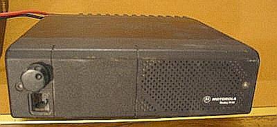
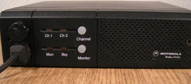
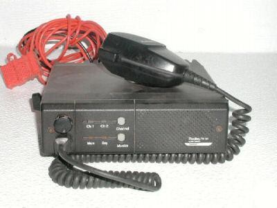
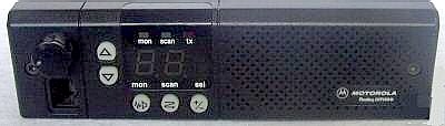
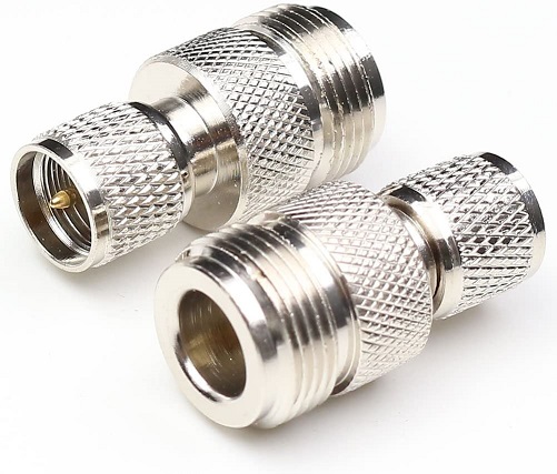
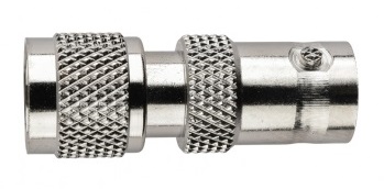
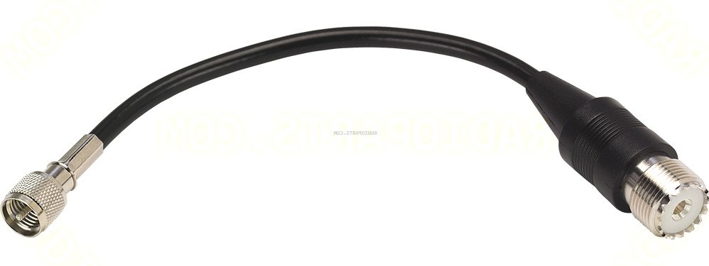
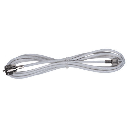
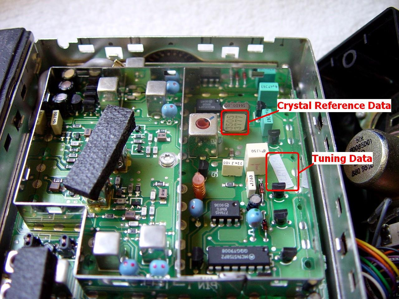
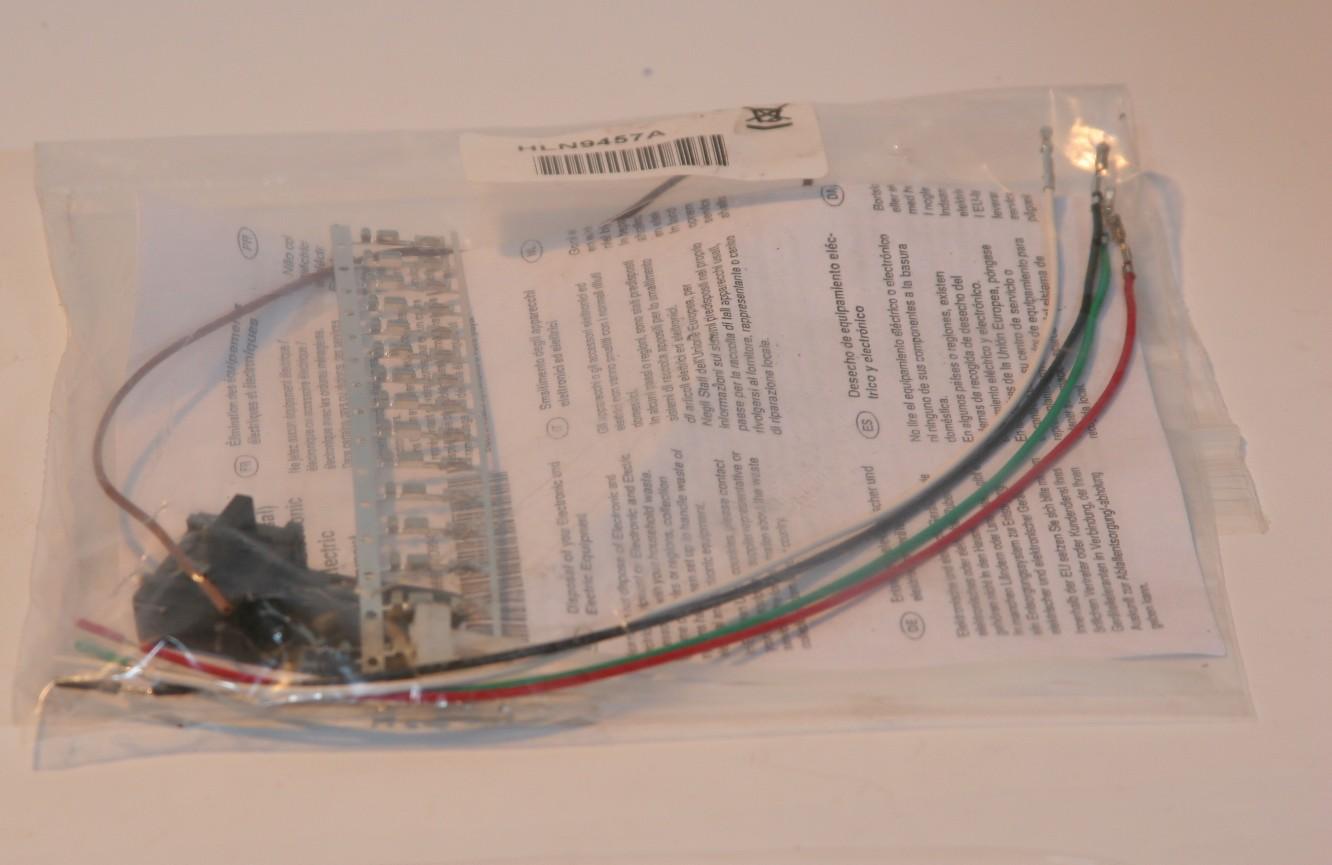
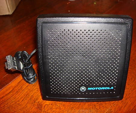
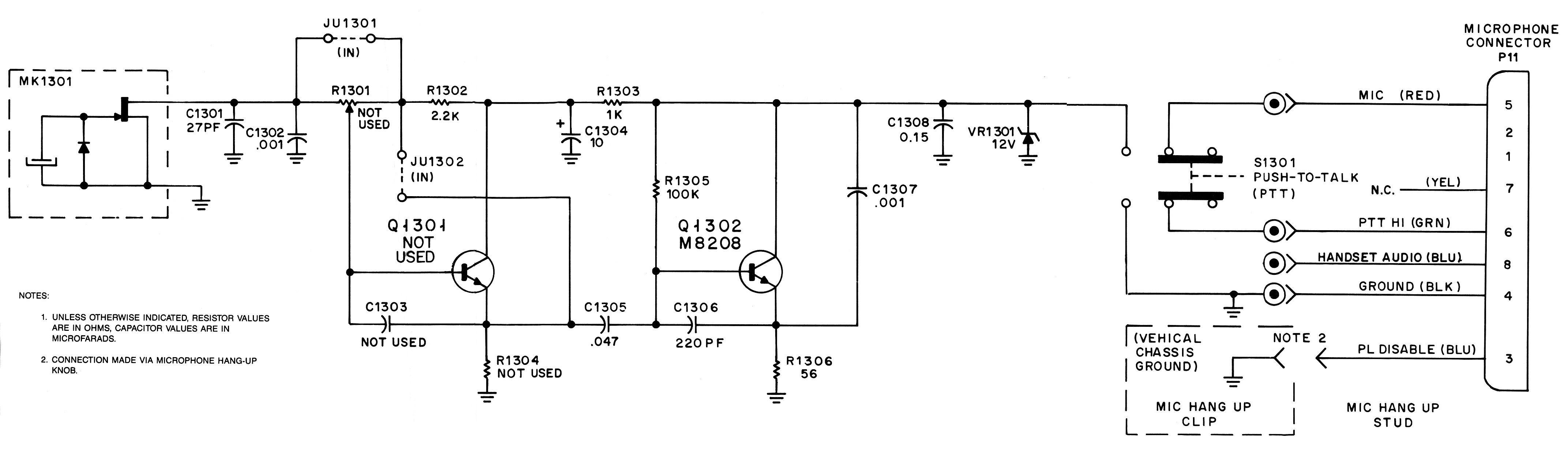
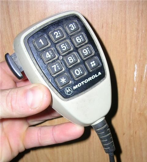
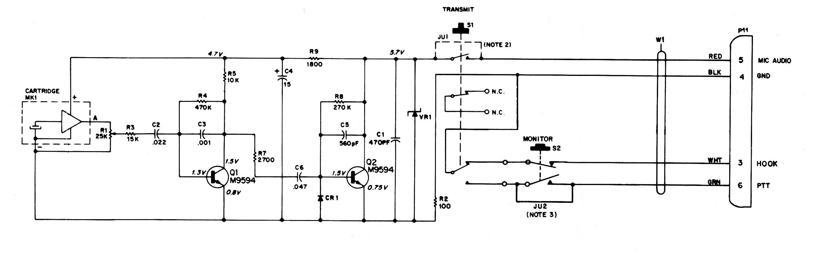
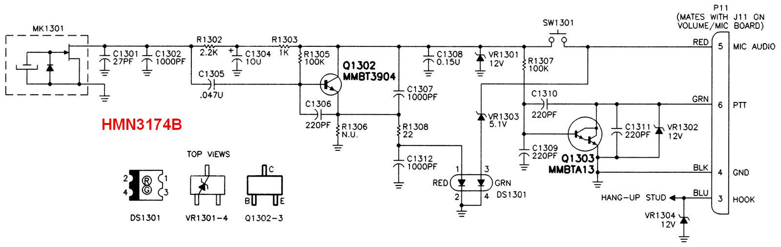
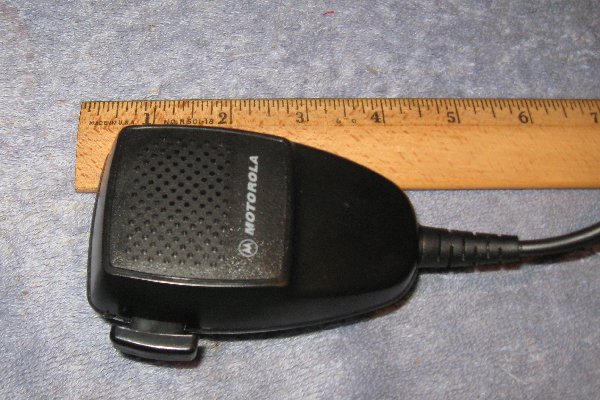
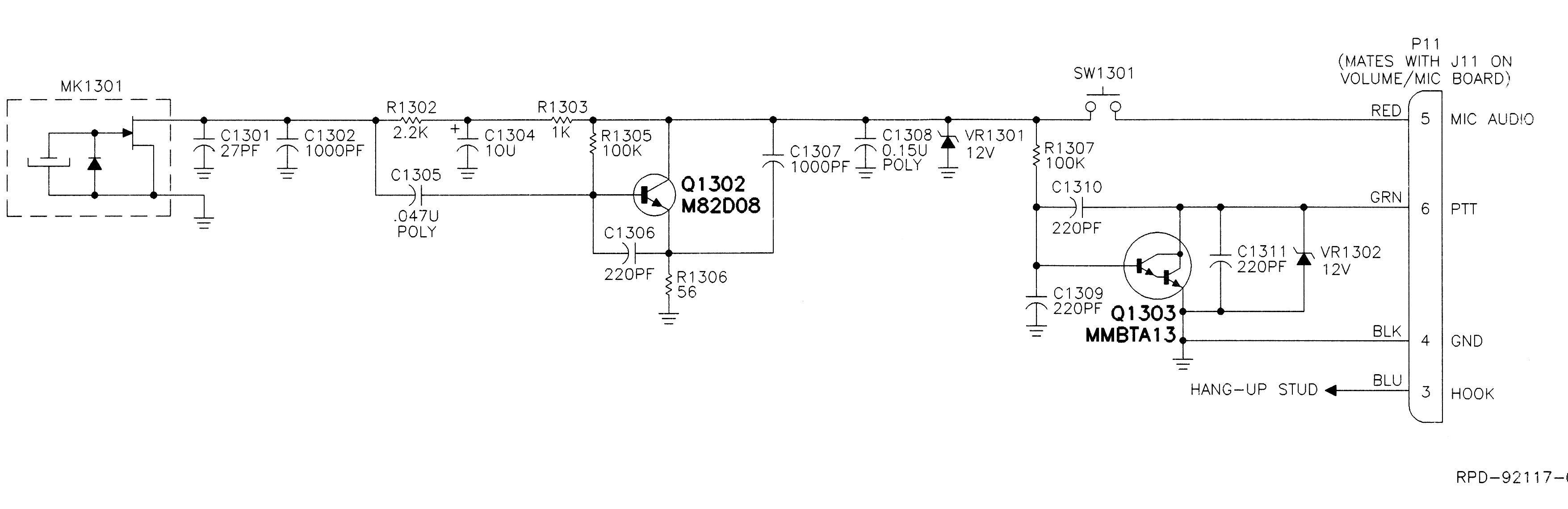
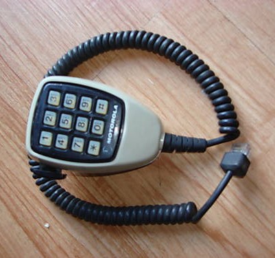
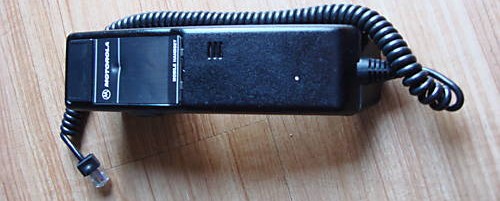
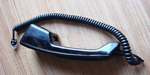
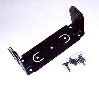
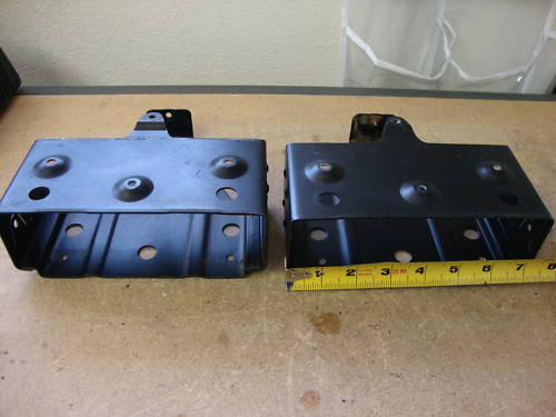
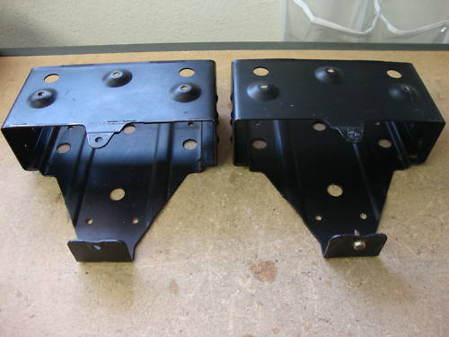
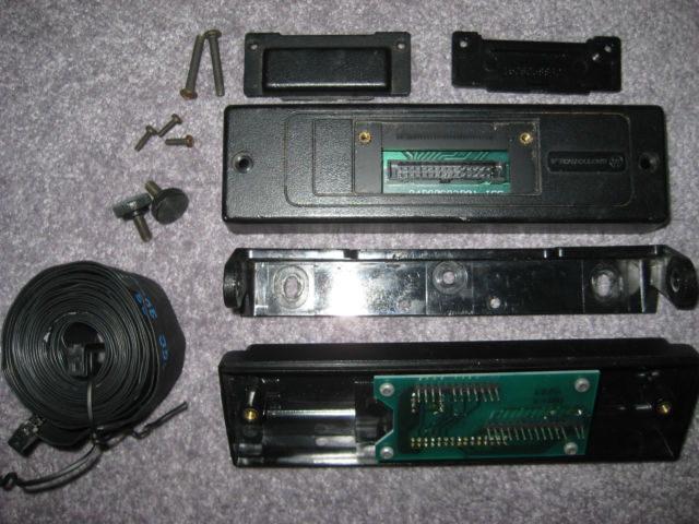
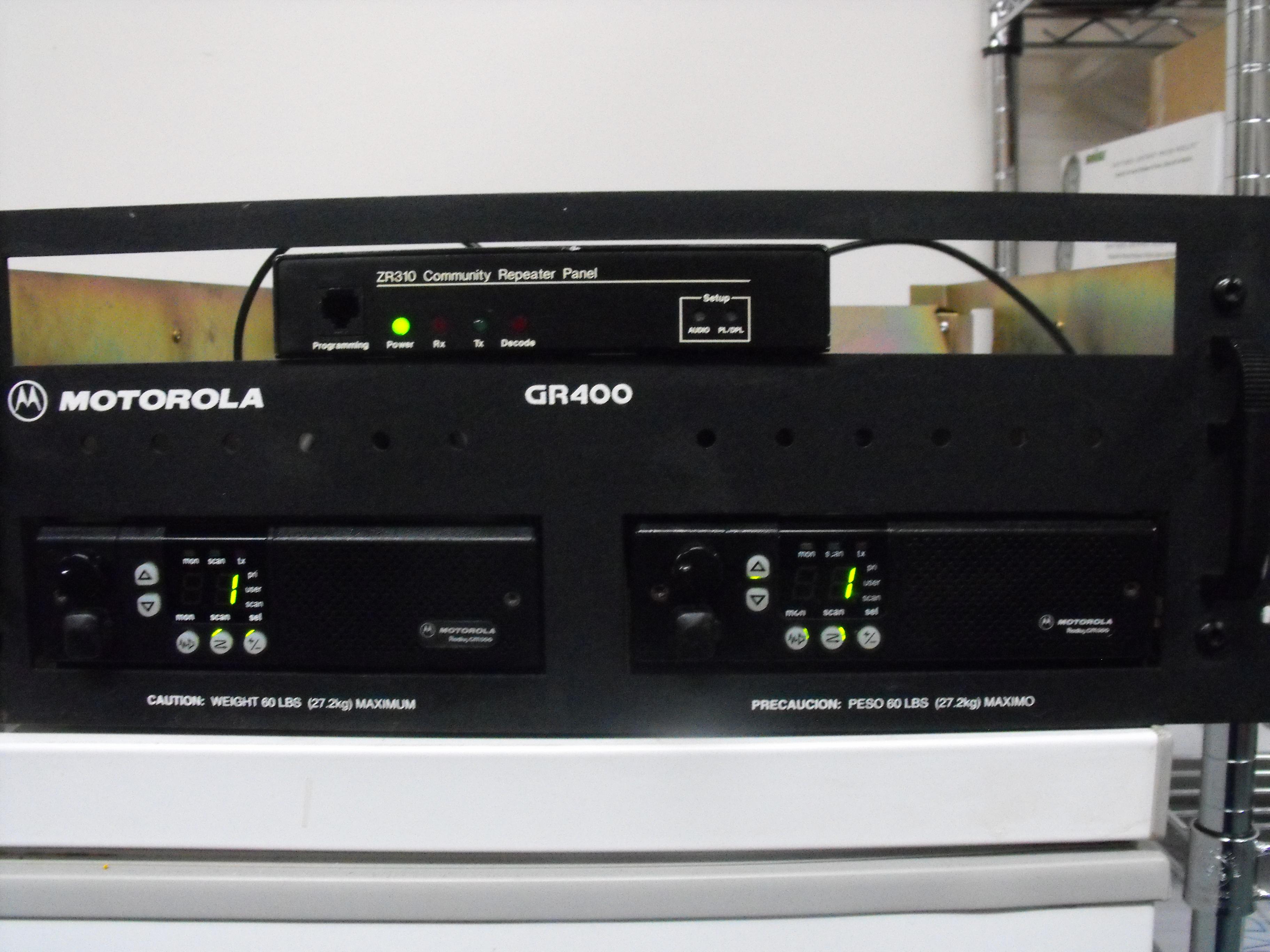
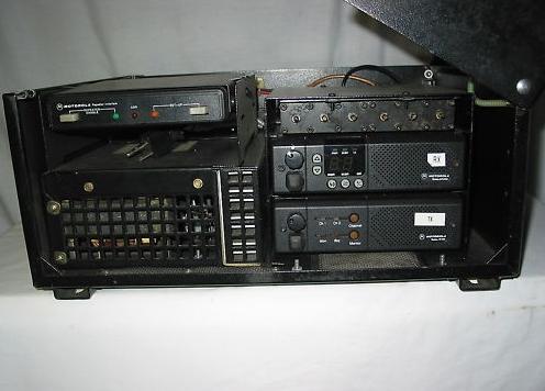
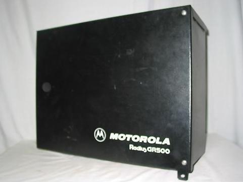