Back to Home
Compiled, HTML'd and Maintained by Mike Morris WA6ILQ

|
Return to the Motorola index Back to Home |
An Overview of the R1225 Full Duplex Radio Module used in the GR1225 and RKR1225 Repeaters and in the Narowband Upgrade Kits for the GR400 and GR500 Repeaters Compiled, HTML'd and Maintained by Mike Morris WA6ILQ |
|
CONTRIBUTIONS OF INFORMATION FOR THIS PAGE WOULD BE GREATLY APPRECIATED.
As an example we'd love to have a PDF of the R1225 RSS / CPS Programming Manual (p/n 6880904Z93)
(or the loan of a paper copy we can scan and return). That book would answer a LOT of questions.
One of the things we are missing is the error codes - like 58 and FF. I'd like to add a section on how to recover from each of the errors.
We also need an article on the specific patch locations for the CPS so that 146-174 MHz becomes 144-174 MHz and 449-474 MHz becomes 440-470 MHz.
Overview:
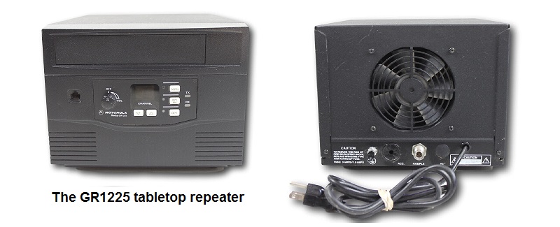
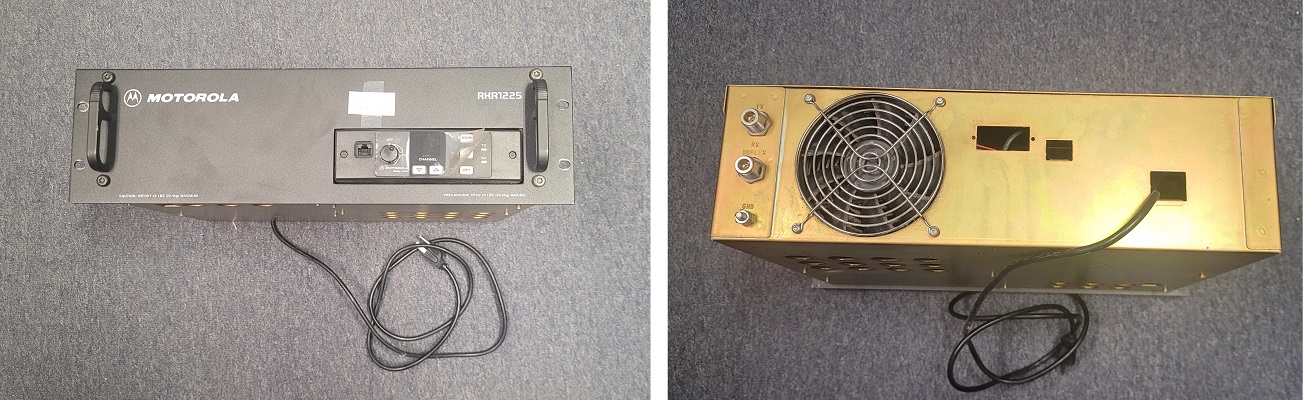
The GR1225 is the cube-shaped tabletop / desktop repeater, the RKR12225 is the rack mount version, and the R1225 is the core full-duplex radio inside both of them. The M1225 is a 4-channel or 20-channel low duty cycle mobile, the P1225 is a low-end handheld.
The R1225 is a full duplex VHF or UHF repeater module that was created to meet the narrowbanding requirements of the late 1990s. The R1225 was essentially a full duplex 16 channel GM300 mobile radio except with dual antenna jacks, could be programmed for wideband or narrowband on a per-channel basis, and could be a base station, or it could be a basic repeater. It is the core of the GR1225 desktop / tabletop repeater and the RKR1225 rack mount repeater. The R1225 module was also the core of the narrowband upgrade kits for the GR400 (rack mount) and GR500 (wall mount) packaged repeaters.
Supposedly the name "1225" came from the 12.5 / 25 KHz narrowband / wideband specification. Like the GM300 the R1225 VHF was 146-174 MHz, but the UHF was 444-474 MHz instead of 438-470 MHz and no 406-420 model was offered.
The GR1225 replaced the GR300 in the Motorola product line, the RKR1225 rack mount repeater replaced the GR400. The RKR1225 was infamous for having a front panel volume control but no speaker or even an external speaker connector. More than one had a Micor, Maxtrac or GM300 external mobile speaker (or at least a 3.5mm / 1/8 inch earphone jack) mounted to the front panel under the word "Motorola". The RKR1225 was cancelled in October of 2008.
The R1225 module and the GR1225 tabletop / desktop repeater both were cancelled in June of 2008, the end of Motorola support was June 2013. There is nothing in the current Motorola product that provides the same functionality in a similar physical size module - the nearest thing that I know of is the Icom VHF FR5000 (or FR5300) and the UHF FR6000 (or FR6300). Both are similar in the width but slightly taller / thicker (and with more features and much better technically).
The four known models of the R1225 module were:
| Band (MHz) |
R1225 Module Model |
GR1225 Desktop Model |
RKR1225 Rack Mount Model |
RF Power (Watts) |
RF Power Amplifier Module Part Nmber |
Notes |
|---|---|---|---|---|---|---|
| VHF 146-174 |
M03GRC90C2AA | NH5165 | H5165 | 1-10 | (anyone have this?) | The author has seen one programmed down to 144.55 MHz but there was some loss of receiver sensitivity. |
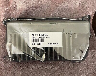
| M43GRC90C2AA | NH5158 | H5158 | 25-50 * | HLD3014A | ||
| UHF 444-474 |
M04GRC90C2AA | NH5164 | H5164 | 1-10 | HLE3770A or PMLE4145A |
The author has programmed one receiver down to 442.5 MHz and another up to 475.65 MHz with no issues. The low power PAs are rated to 10 watts. Most will do a little more, my personal record is 14.7 watts. |
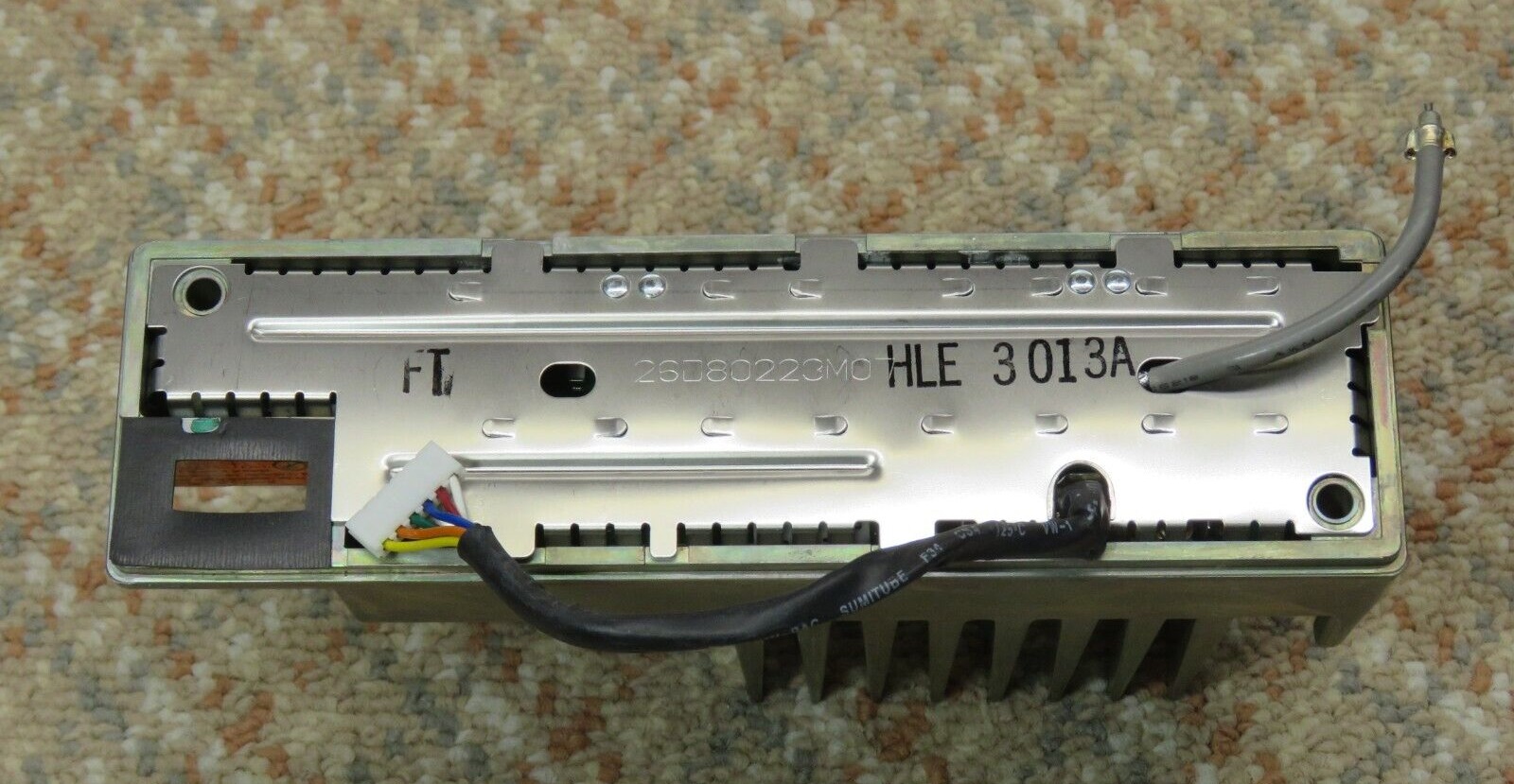
| M44GRC90C2AA | NH5157 | H5157 | 25-45 * | HLE3013A |
* The Motorola Specification Sheet specifically says "Continuous Duty Cycle at 25 Watts; 50% at 45/50 Watts". Do not run the high power units below 25 watts. They run hot when underdriven and run below their rated power level. See the section below titled "The PA Itself". So set your high power R1225 to 25 watts and leave it there.
The author was told there was a Special Products version made for the 406-420 MHz "government range", but he can't find a model number or manual, and doesn't know anyone who has ever seen one. It's quite possible as the relevant RF engineering was already in production in the 406-420 MHz GM300.
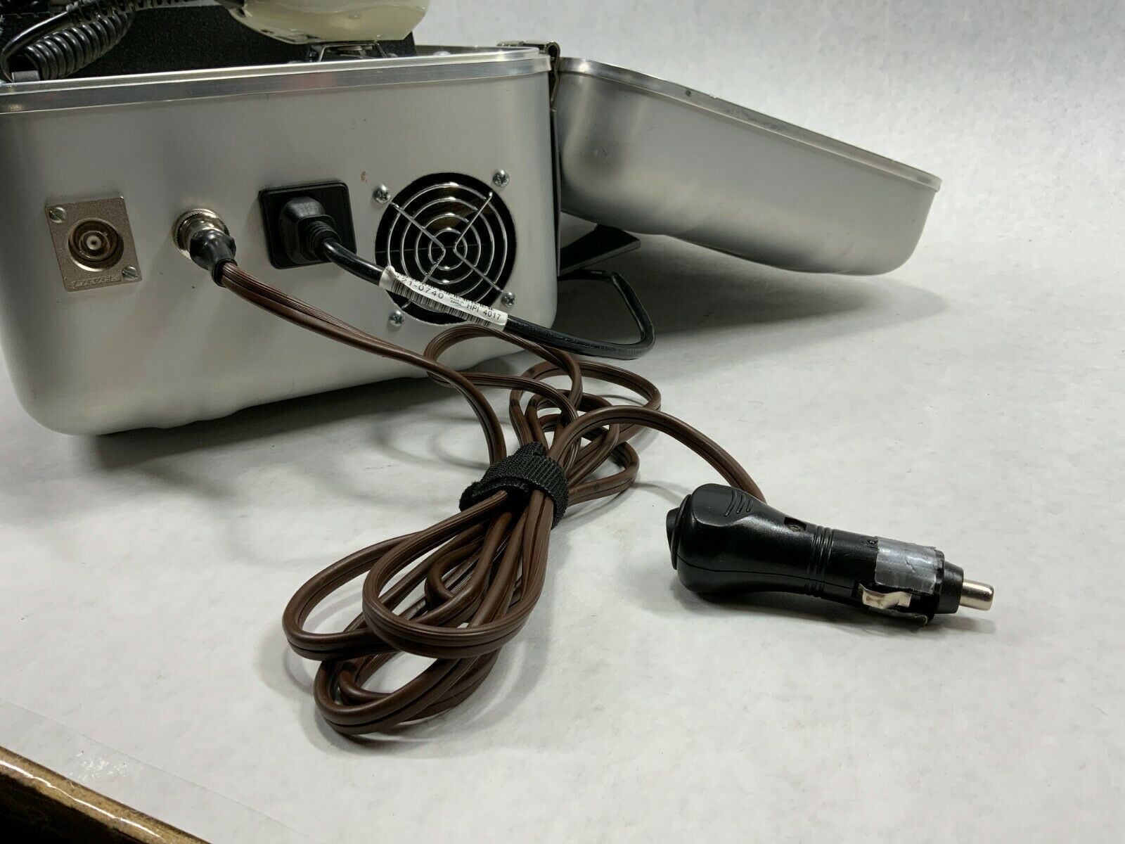
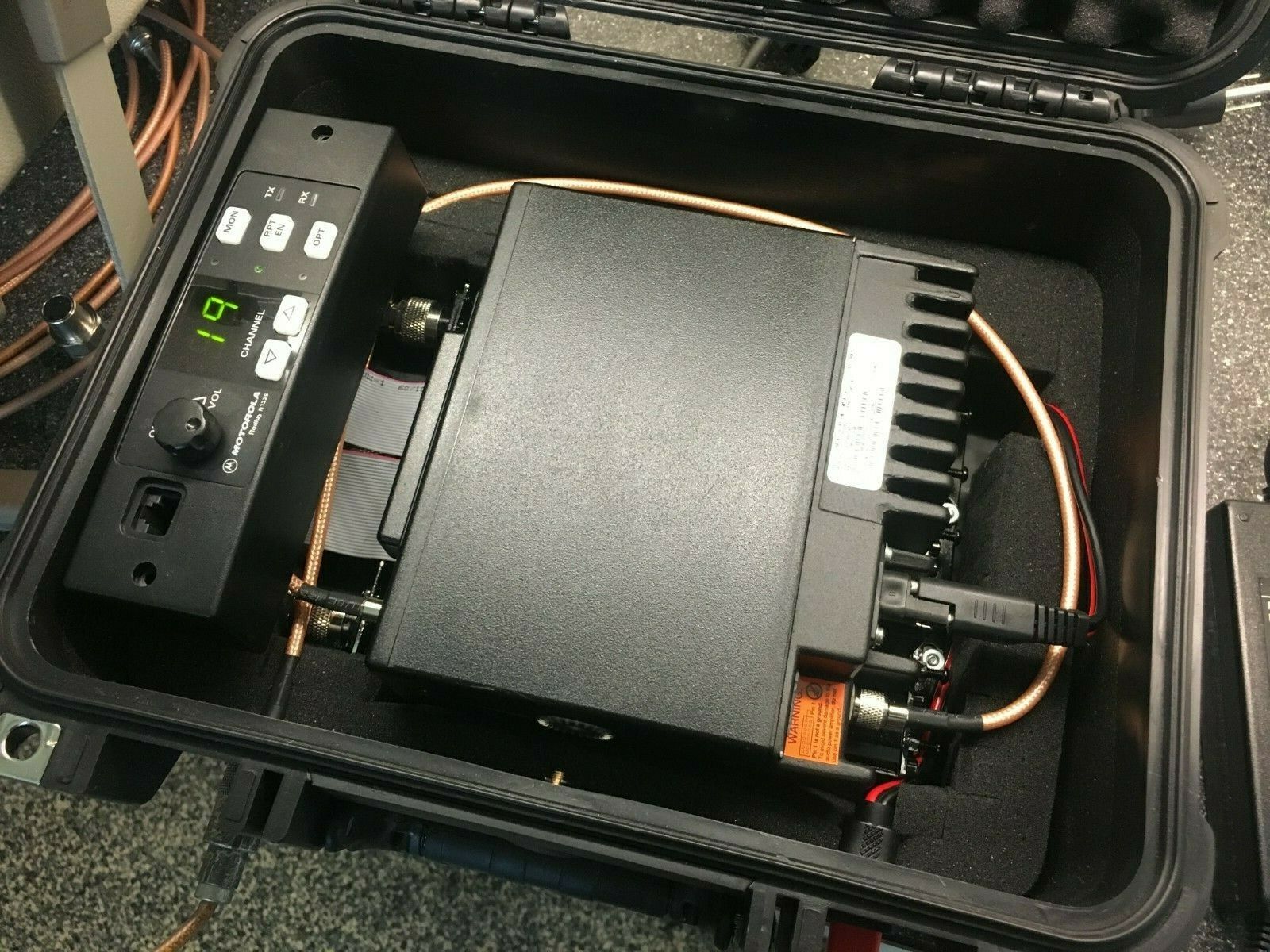
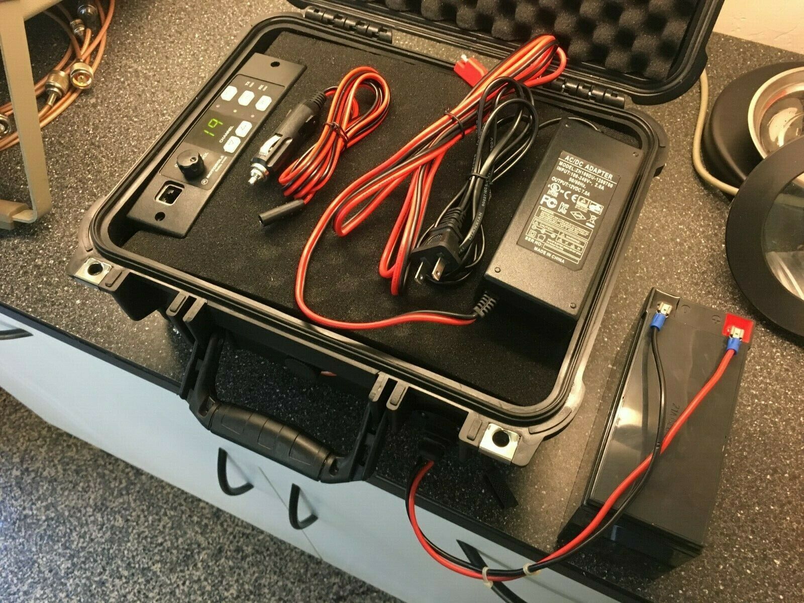
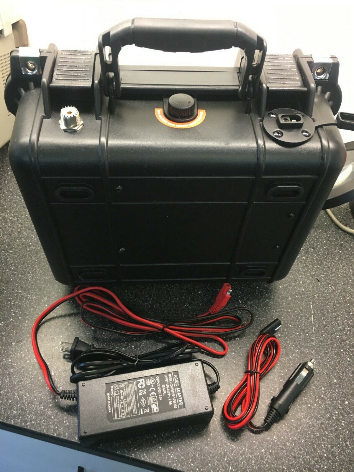
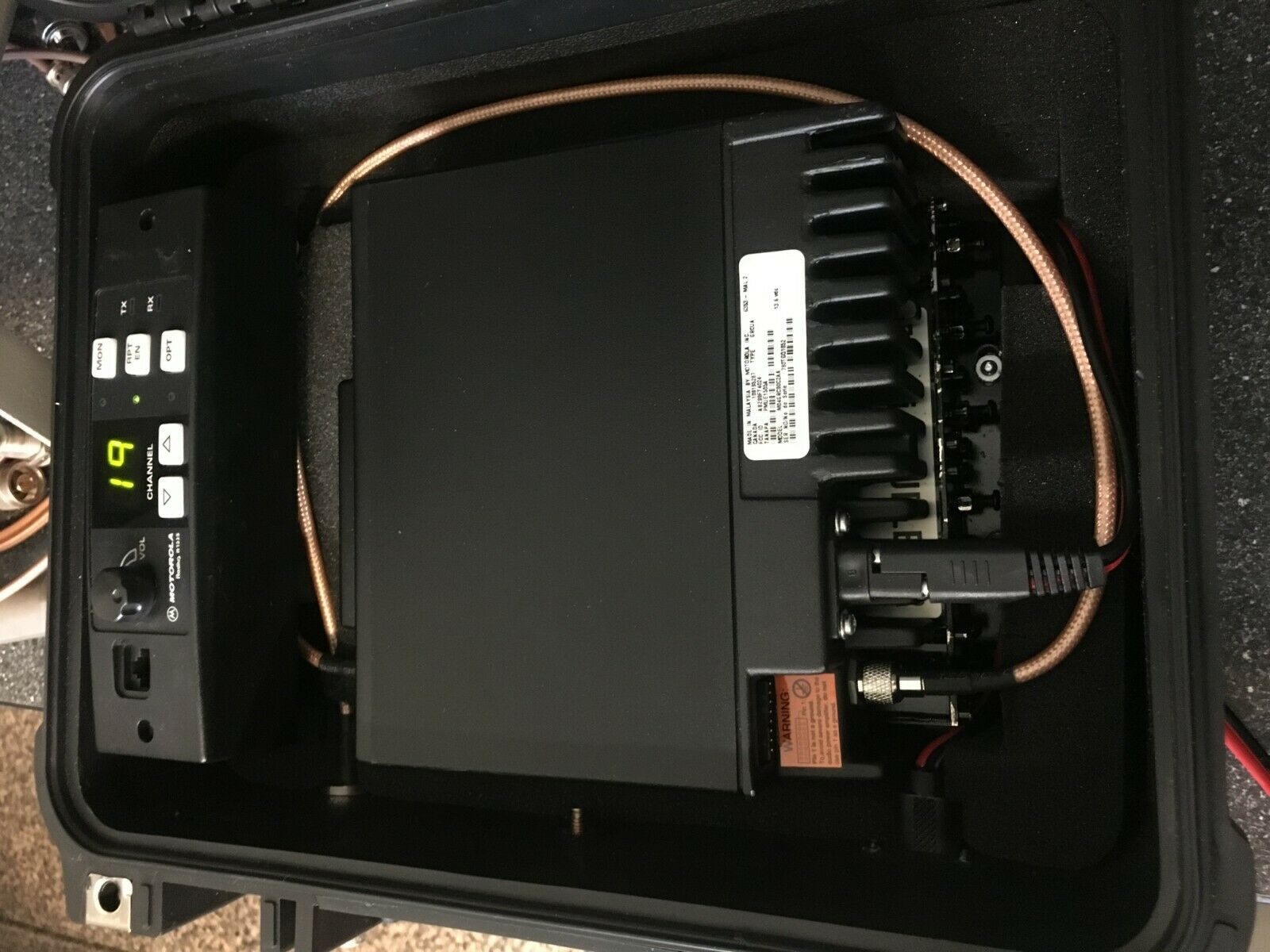
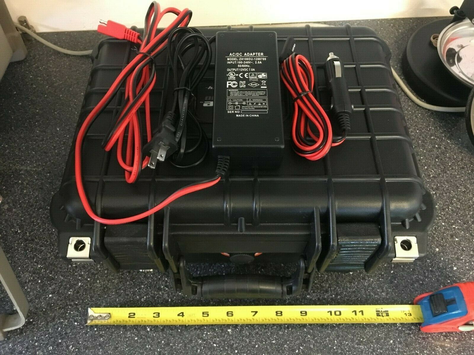
The R1225 module or "brick" also appeared in a few other product lines, including a Special Products UHF briefcase repeater. I'd love to see a photo of that unit! Does anyone know the model number for that unit! Better yet, can anyone supply a PDF of the manual? Or loan us a paper copy to scan?
Several portable R1225 repeaters have been homebrewed, one is here:
Photo 1
Photo 2
Photo 3
Photo 4
Photo 5
Photo 6 I have no idea if it is high or low power, or the band.
A second one, a low power UHF one, is here:
Photo 1
Photo 2
Photo 3
Photo 4
Photo 5
Photo 6
At the time of this writing the author has about 30 of the R1225 units in both commercial and amateur service. Two are VHF, about 25 are UHF low power units, the rest are UHF high power. Every high power R1225 has a pair of fans blowing on the heat sink (controlled by PTT). Every low power one is set for about 5 watts and also has a small fan on the heat sink and is followed by a 100 watt power amplifier. He's always looking for good low power UHF units (even just the low power UHF power amplifiers rear section).
The following frequencies are known to be self quieting and cannot be used with an R1225: 151.200 and 168.000 MHz on VHF and 453.600, 455.500, 459.300, 470.400 MHz on UHF.
The above list came from a Motorola document and naturally did not include any frequencies outside the specified VHF and UHF frequency ranges (below 146 MHz and 444 Mhz and above 174 MHz and 474 Mhz). You can program these units out of band with the tab-key and shift-key trick, so if anyone discovers any more unusable frequencies please let the author know and he'll add them to the above list.
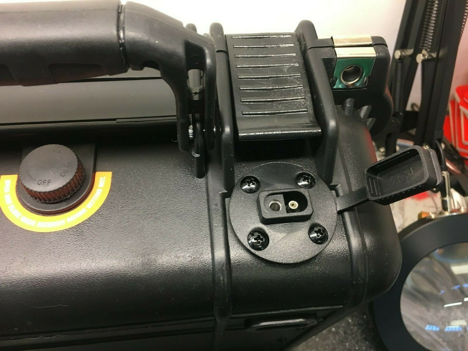
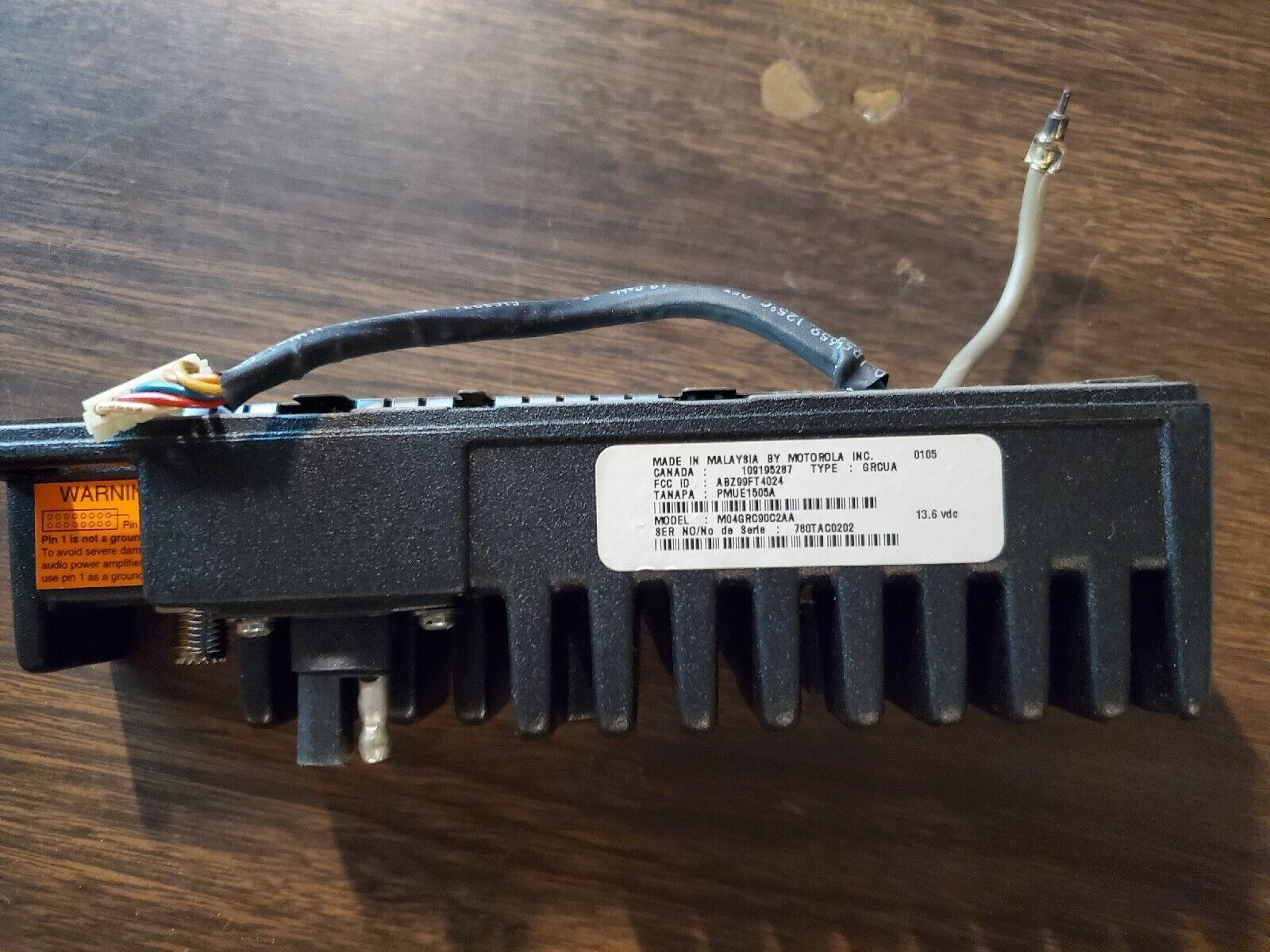
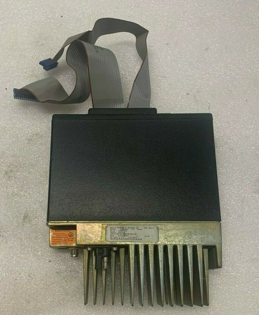
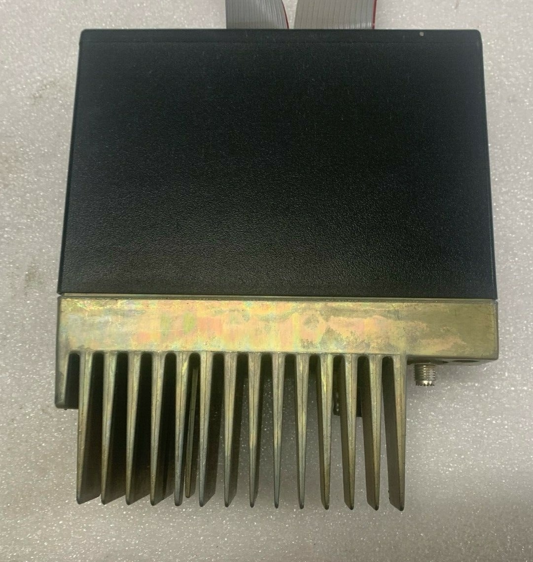
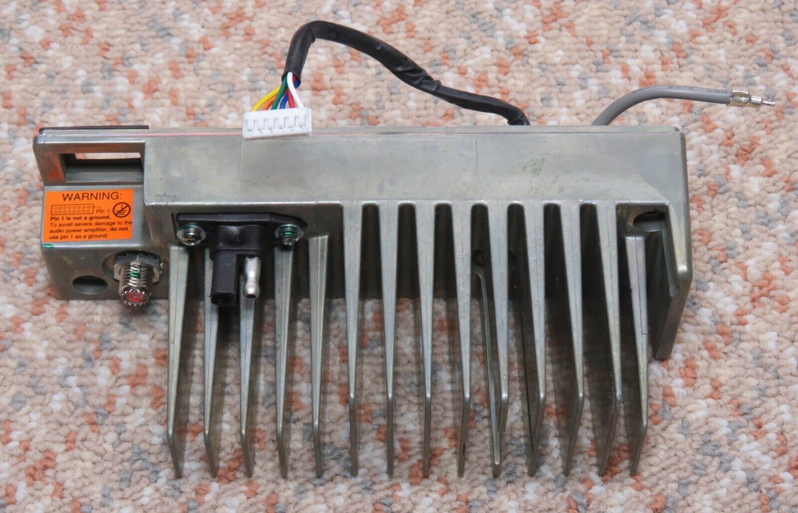
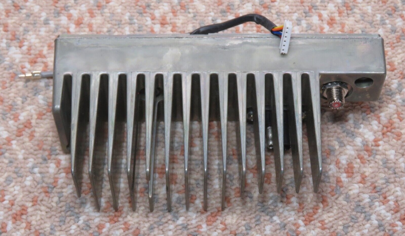
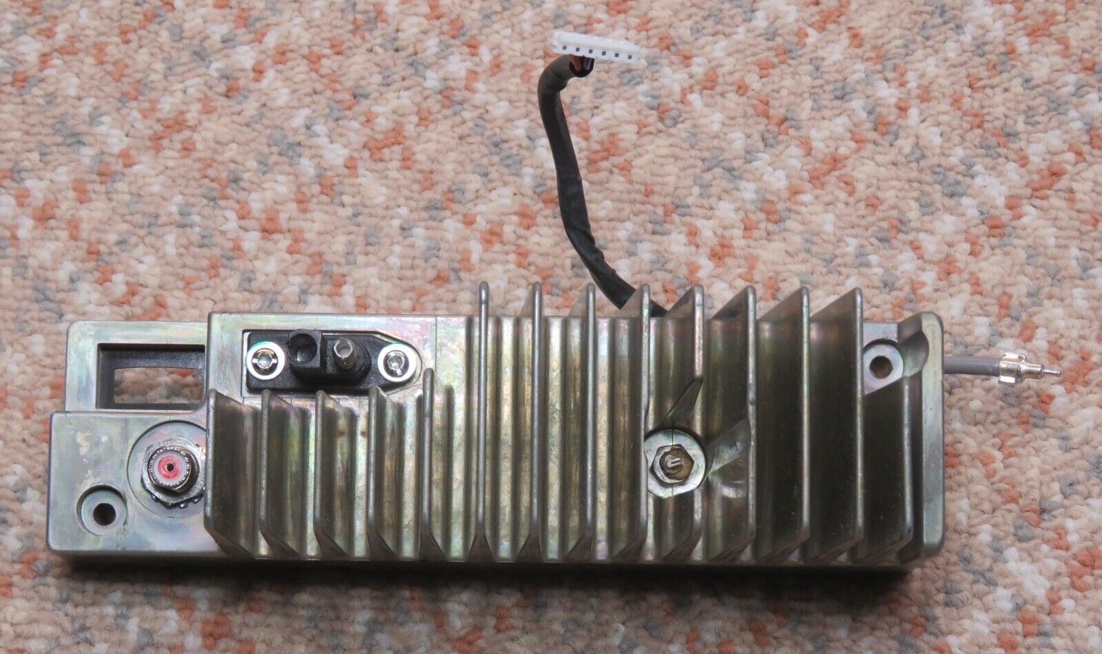
The VHF and UHF low power R1225 modules (photo 1) have short rear heat sink fins (same as the low power GM300), the high power R1225 units (photo 2 and photo 3) have a much larger heat sink. Both the low power and the high power models have two "mini-UHF" antenna connectors, the transmit is on the "rear" (adjacent to the heat sink, similar to the antenna connector on a GM300) and the receive antenna connector is on the "front".
At one time the R1225 high power bare heat sink (part number 26-80475U01) was available as a spare part, and locally several of the large heat sinks were purchased and used to modify / rebuild 406-420 MHz GM300 mobiles (that were used as point-to-point link radios) to increase the duty cycle. Remember, the GM300 has a thermistor-based transmitter shutdown where the Maxtrac and Radius LRA series have a timer based one. Both the GM300 and the R1225 "know" if you have a fan, a larger heat sink, or both. When operated under any measurable duty cycle the high power R1225 needs a fan blowing on the heat sink.
The R1225 module is internally a two board set, very much like the GM300 mobile. The control board appears to be idential for all four models (VHF, UHF< low power, high power). Several knowledgeable people have told me that the control board was factory programmed for low or high power during production. The author has tried to convert several high power units to low power and low power to high power and in every case the module is totally confused. The power set process has not gone well. If anyone has had success please let the author know. Maybe there was a "depot program" that configured the control board? There is a manual power control modification but it has a side efect that defeats the SWR detect and shutdown feature.
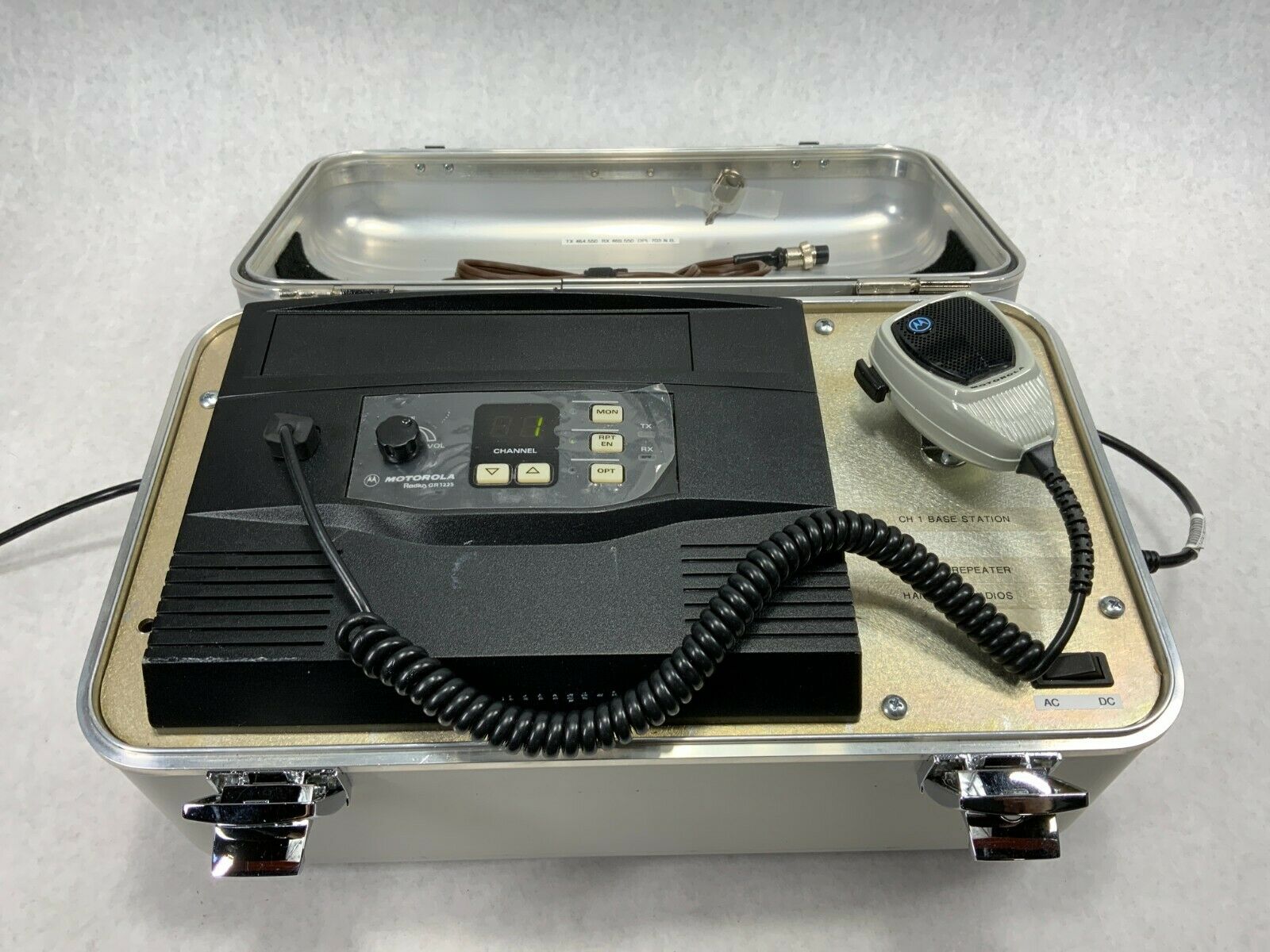
The GR1225 tabletop / desktop repeater (the housing is labeled as a HLN3037) was designed as the replacement for the GR300 desktop / tabletop repeater (which used a pair of GM300 family mobile radios) and was intended for low-duty-cycle full duplex applications like a a golf course, a school campus, a shopping mall security or housekeeping department, a construction site, a manufacturing plant, or some other non-public-safety repeating application. You could use it as a dispatch base by adding a desk microphone and turning up the receiver speaker volume. The GR400 was the rack mount equivalent (the housing kit was HLN3102, which had room for a DC power supply but did not ship with one) and the GR500 was the wall-mount version (housing kit was HLN3103). Three different brochures or the GR1225 are here, here and here. The first brochure mentions only two of the optional controllers, the second shows more of the optional controllers, which included community repeat and autopatch options. The third mentions a trunking option.
The rack mount version of the GR1225 was the RKR1225. The GR1225 desktop housing has a speaker, the RKR1225 rack mount housing does not. (Why? What were the designers thinking?) Other than the missing speaker the GR1225 and the RKR1225 were electronically identical and differed only in the physical mounting. Here's the RKR brochure. The RKR was discontinued in October of 2008.
The GR1225 desktop / tabletop repeater and the RKR1225 rack-mount version both have one of the four R1225 radio modules as the heart of the unit. In addition to the module the cabinet contained a HLN9514 control panel, a power supply and any combination of three optional modules:
Mounting:
The R1225 module has two side mounting bolts just like the GM300 mobile. Either M5 or 10-32 thread bolts are will fit. If you provide your own bolts you should trim them to about 1/4 inch length into the radio body – any longer risks damage to the electronics inside the R1225.
Power Supply:
The early units were shipped with an analog supply, later units used switching supplies. The most common power supply that I have seen in GR1225, RKR1225 and some GR400s is the same HPN90333A (made by DuraComm) which was used in the GR300. These aren't the best power supplies, and some have had RF noise generation issues. There is a reason that Motorola switched to the HPN9041 (a relabeled Astron SL-15) part way through production. Your author will NOT use a HPN9033 at a hilltop site, there are too many other good supplies out there… A GR1225 service manual addendum added the info on the HPN9041 Astron supply to the manual.
The stock GR500 power supply is the HPN9005 which is made by StarWerks, Inc.
Both power supplies output can supply 13.8 volts at 15 amps continuous and 17 amps intermittent duty. The switching supplies weigh about six pounds. The conventional supplies are considerably heavier.
The HLN9514 Control Panel:
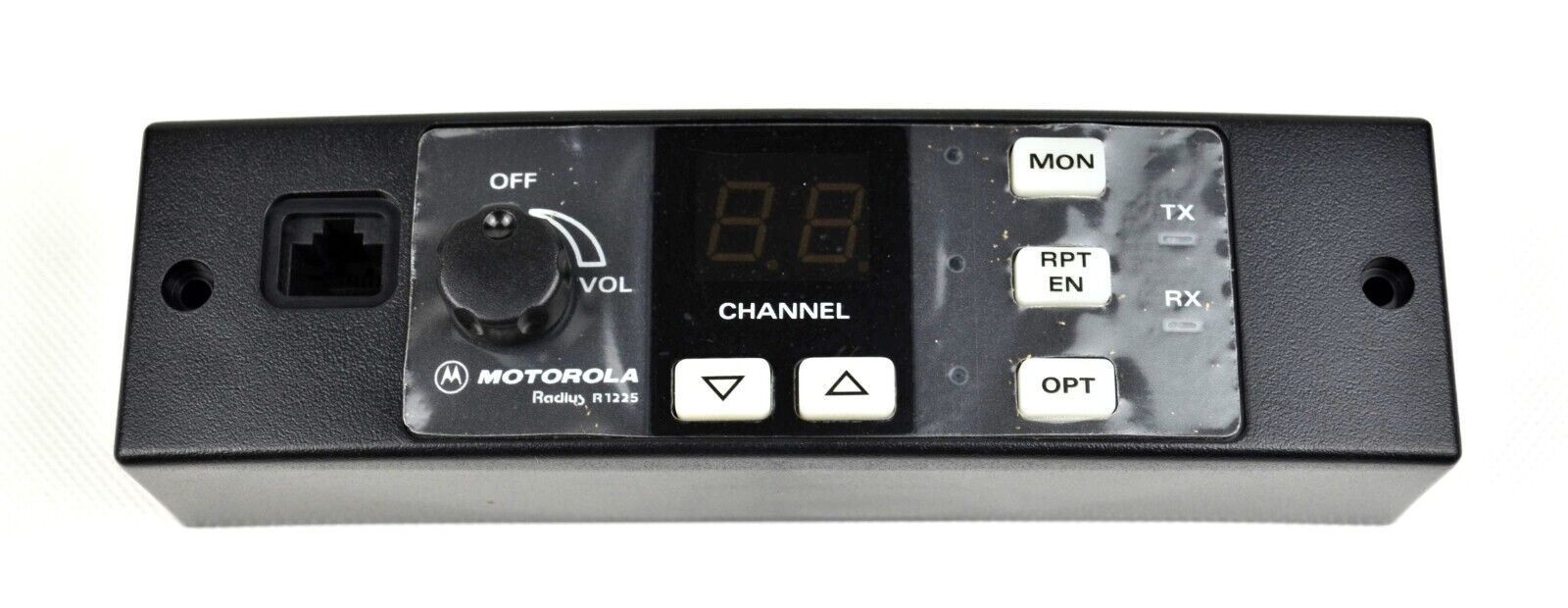
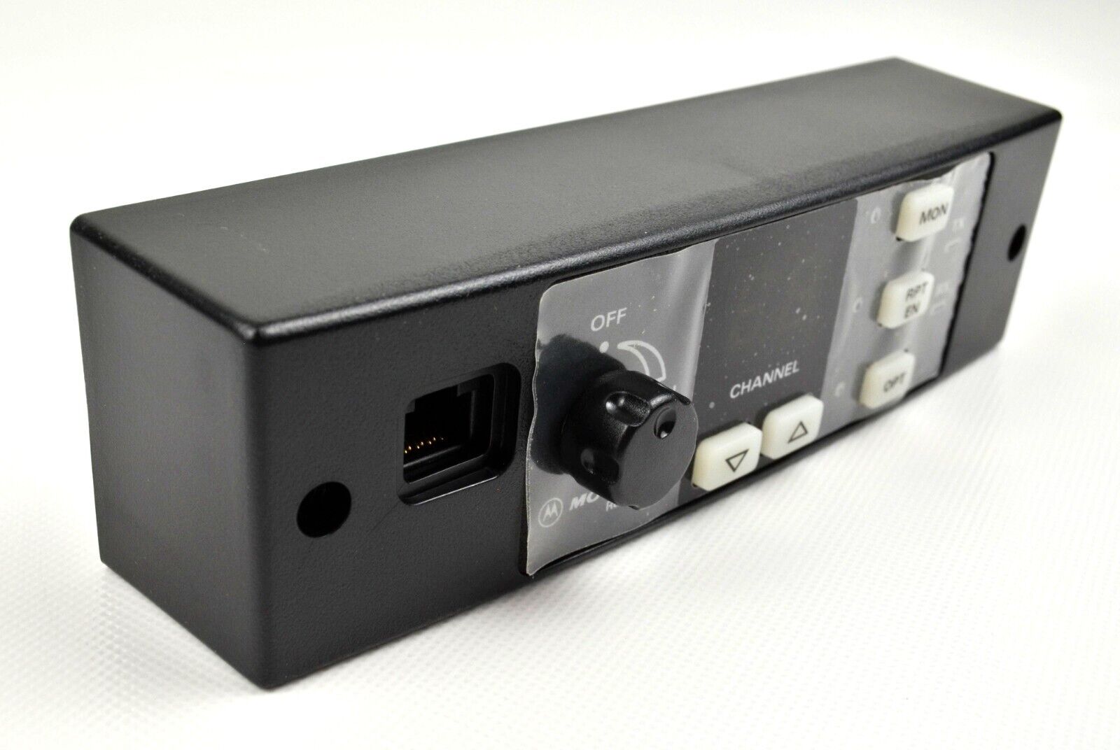
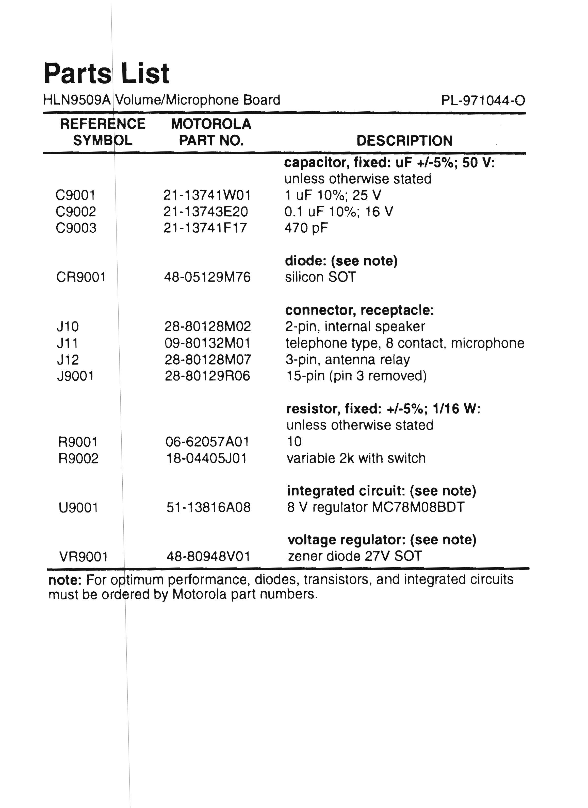
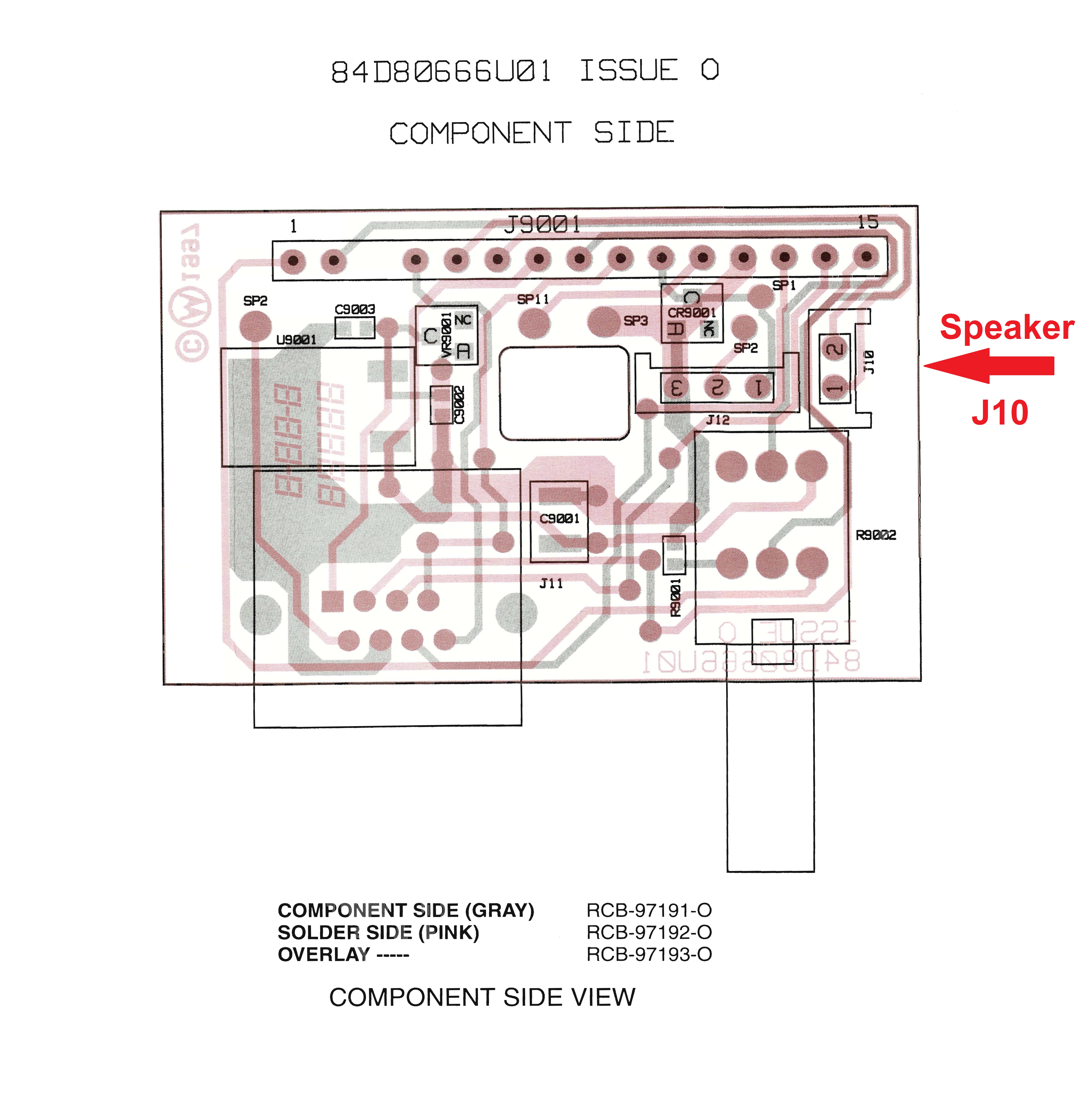
The HLN9514 Control Panel is most commonly seen mounted in the GR1225 or the RKR1225 cabinet. The info on the control panel is duplicated in both the GR1225 and RKR1225 manuals - Motorola did not offer the control panel documentation as a separate document (but we created it and offer it below). If the R1225 radio module is programmed for only one channel (i.e. in repeater or link service) the control panel is not required for everyday operation… Except that you won't have a power on LED, a Transmit Indicator LED, a microphone / programming jack or a volume control… and without a volume control you won't have any speaker audio. And the control panel does not have a speaker but it does have a connector for a case mounted speaker (like the one in the GR1225 tabletop case) or you can add a tiny speaker, or a 3.5mm / 1/8 inch earphone jack for an external one.
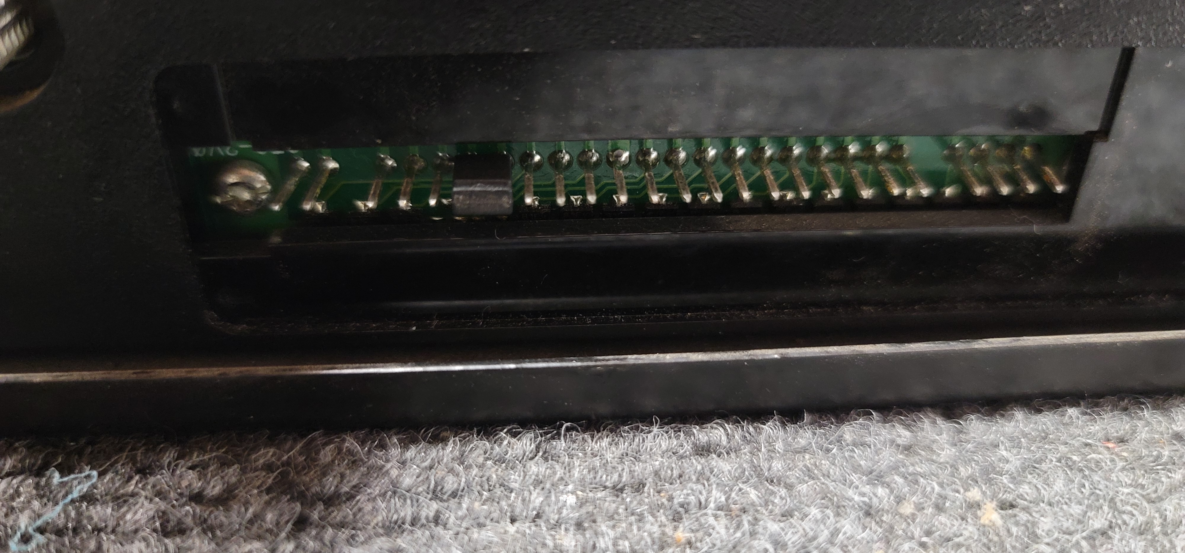
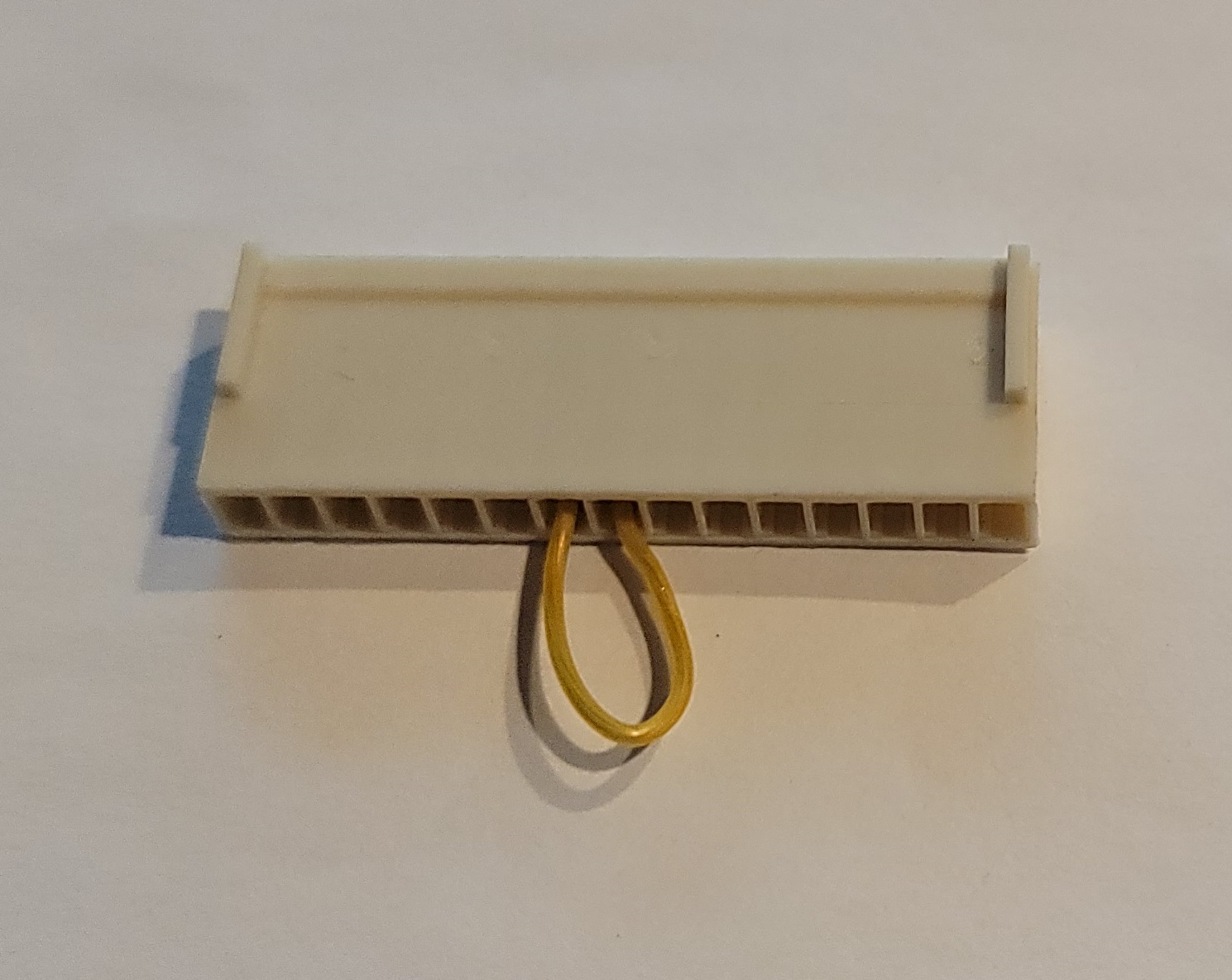
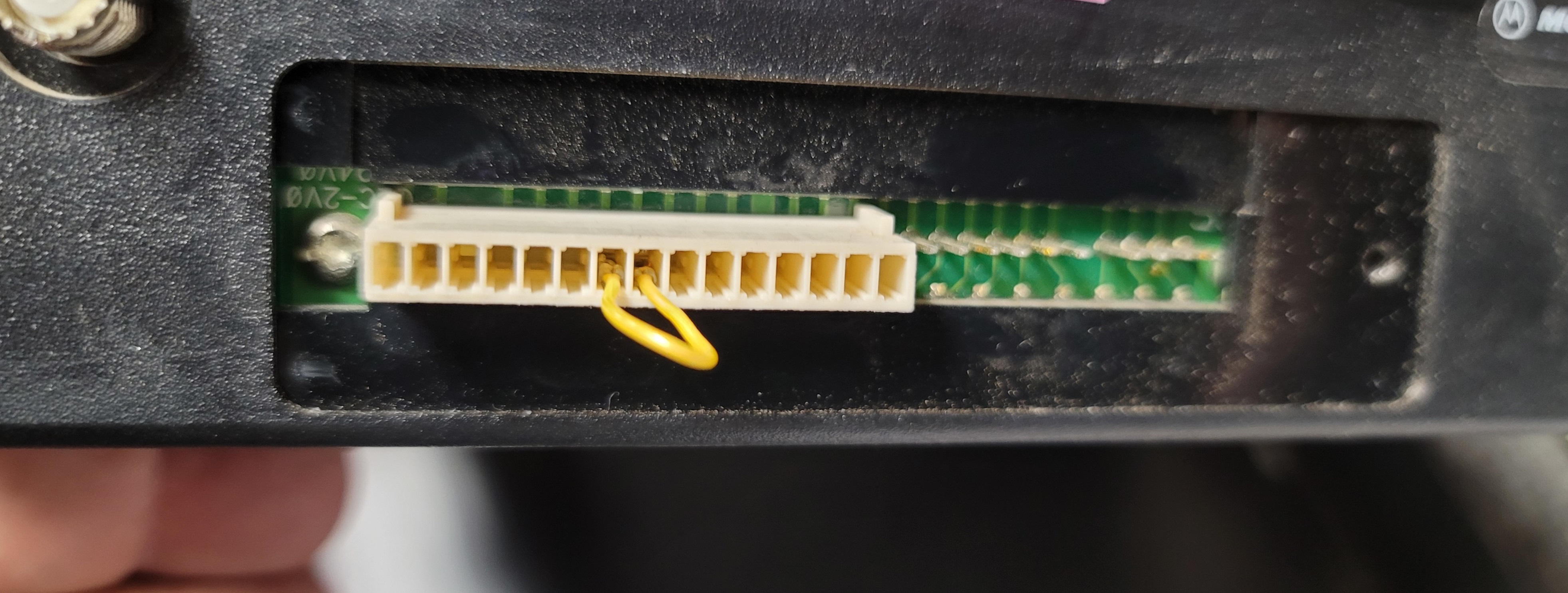
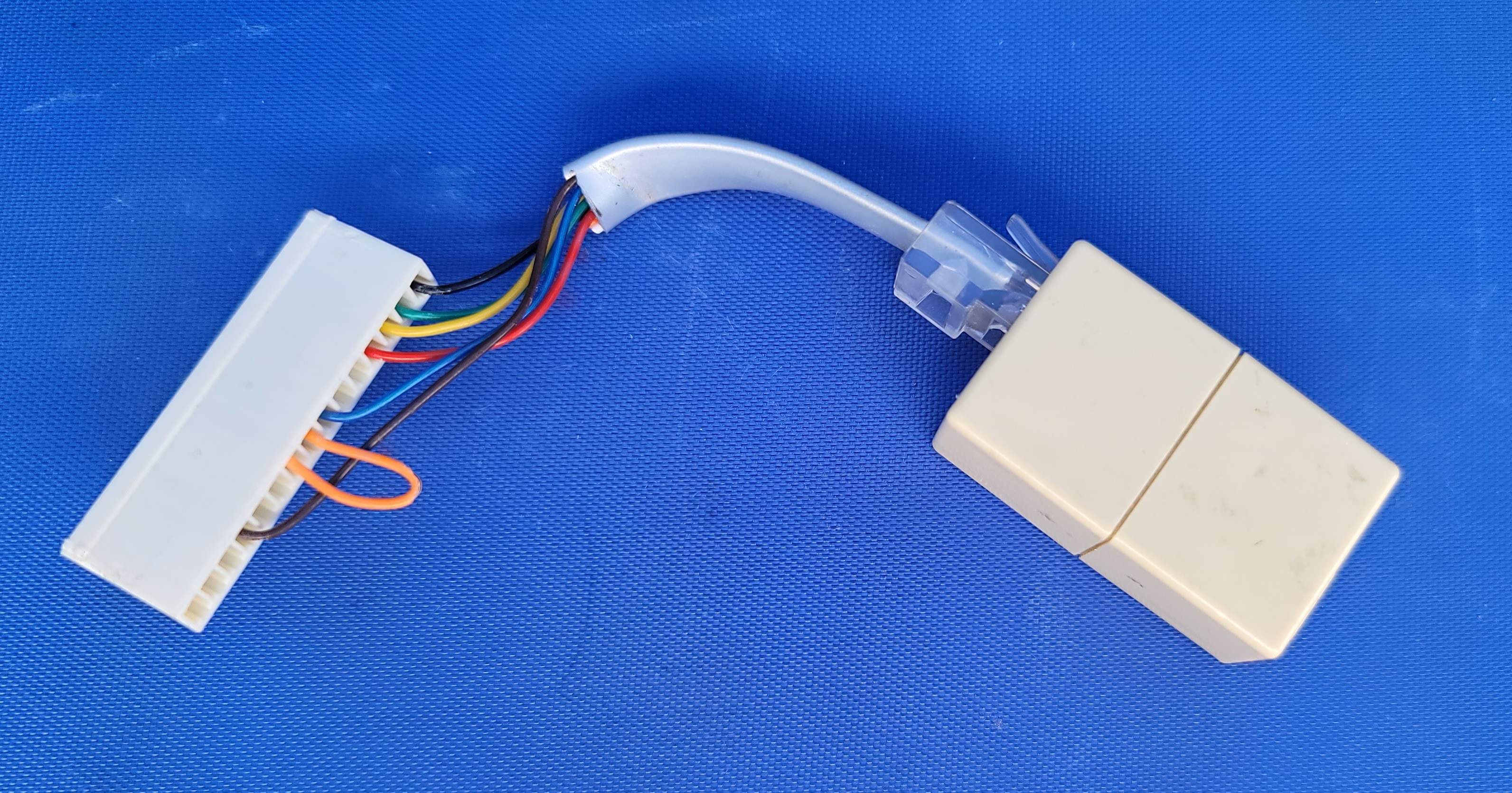
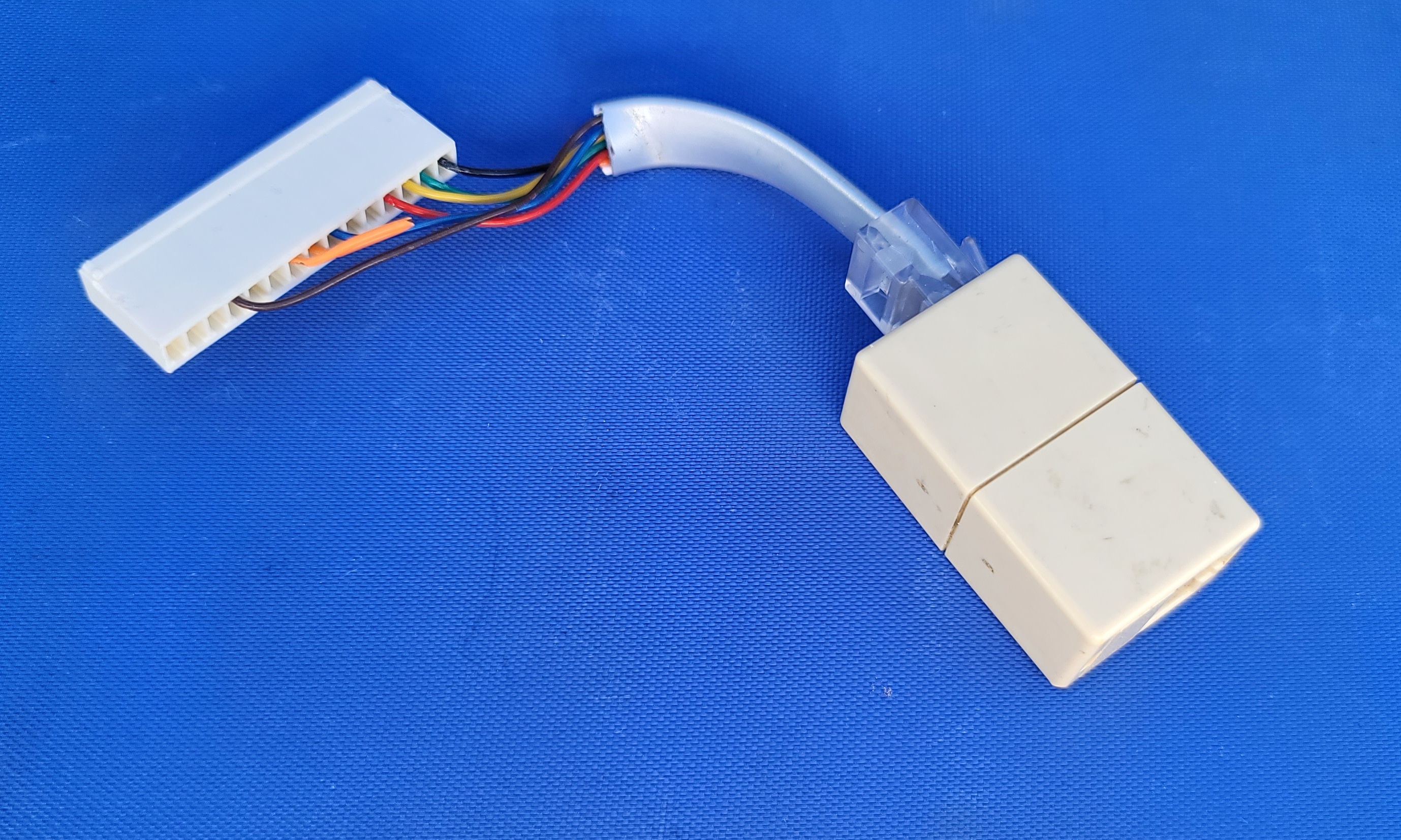
Operation without the HLN9514 control panel connected requires nothing more than jumpering the two pins that normally connect to the power switch on the volume control. There is a row of 27 pins (spaced the standard 1/10 inch apart) on the front of the R1225. The leftmost pin (closest to the receiver antenna connector) is pin 1 of J8, pin 3 is missing. Pin 8 is unswitched +12vDC and the power switch connects pin 8 to pin 7 (the repeater internal power buss). See the table below. Note that accidentally grounding either pin will melt a trace inside the R1225. Simply jumpering pin 7 and 8 with a Berg jumper (one of the two-pin jumpers you find on computer motherboards) or an official Motorola test jumper plugged into the face of the radio like this is enough to get the R1225 operational as a repeater or as a full duplex link. Your author has most of his R1225s in service with Berg jumpers.
Anybody know who makes the plastic body of that white test jumper? And the part number for it and the pins?
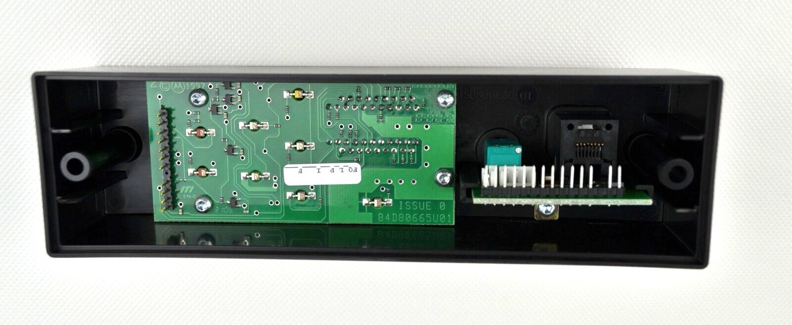
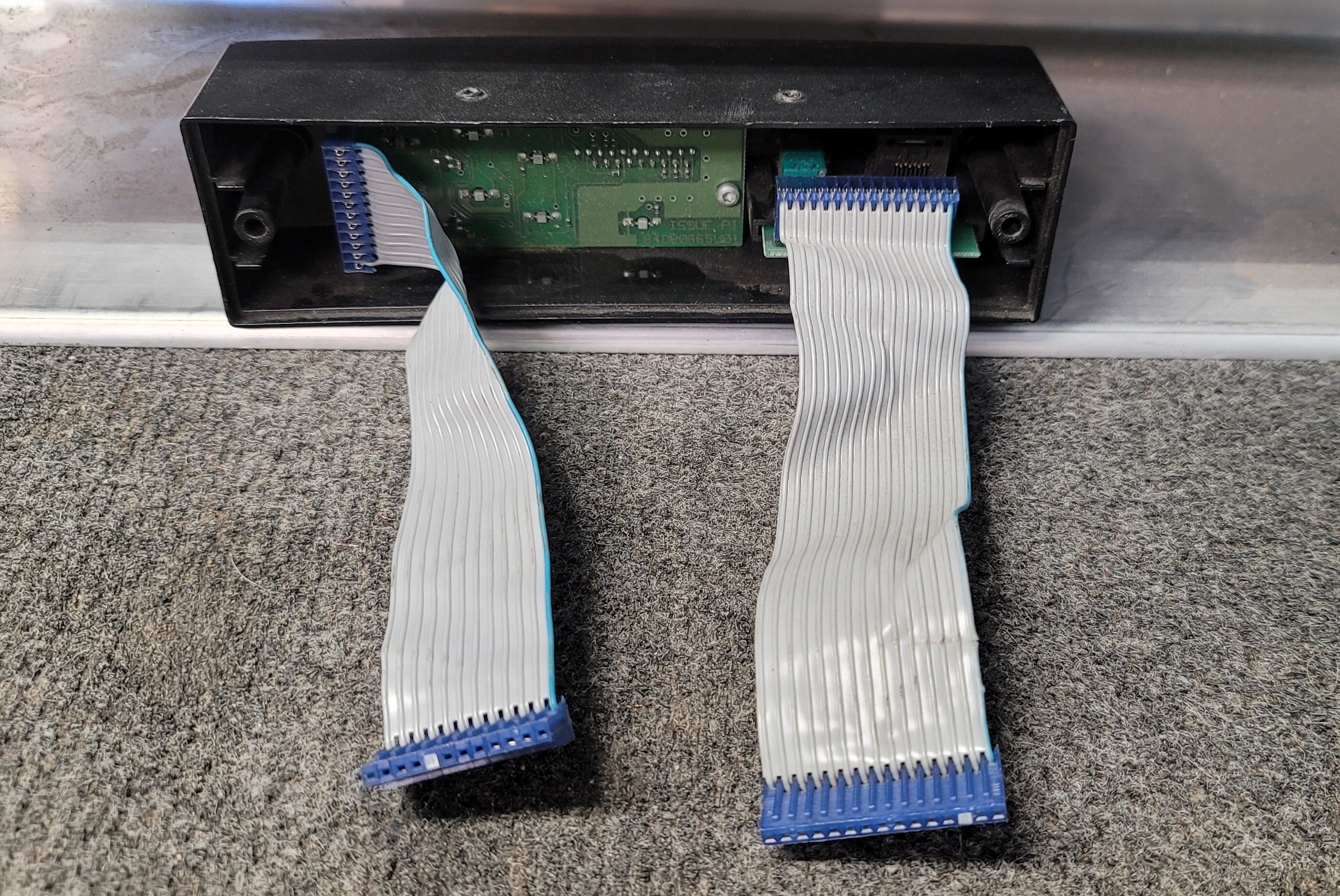
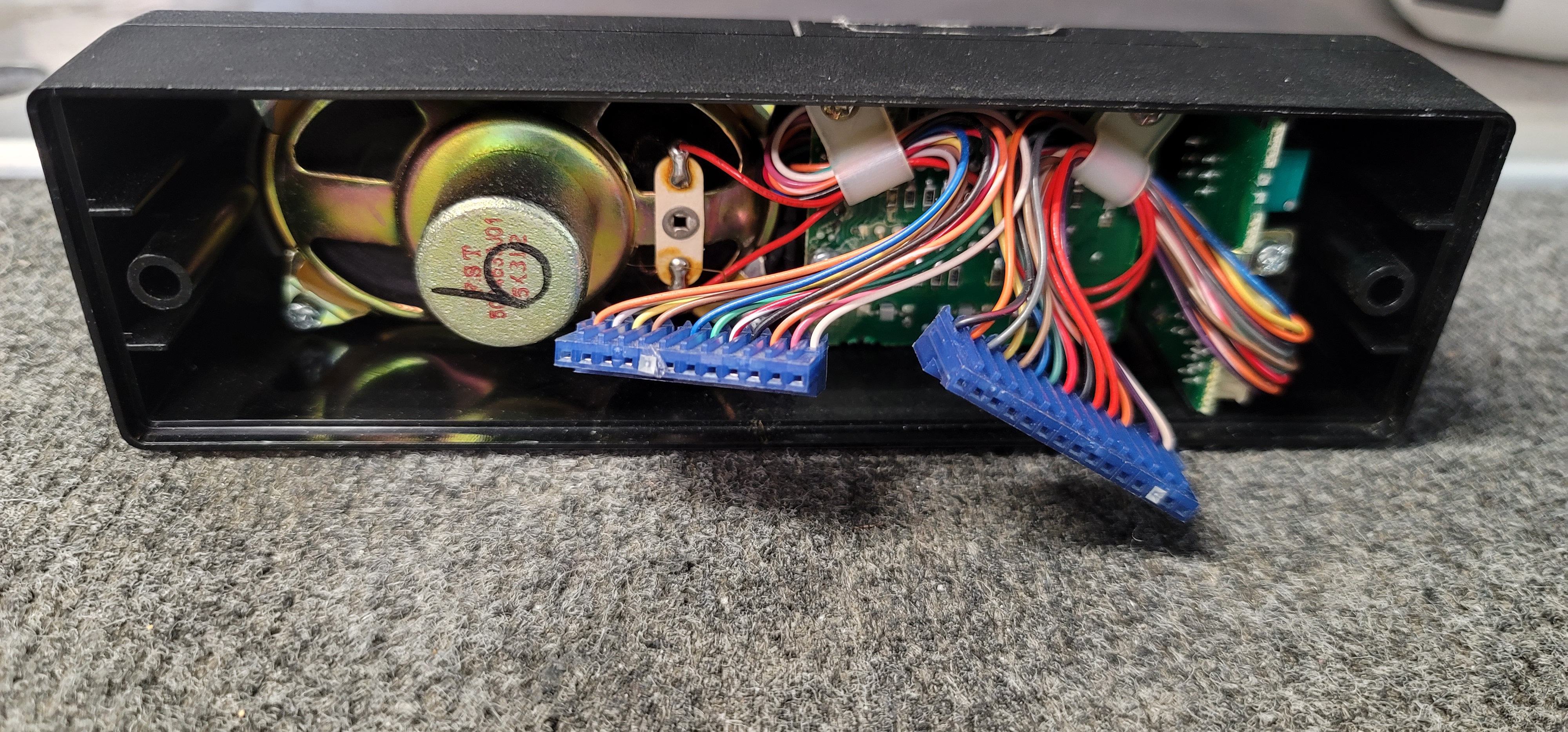
The HLN9514 control panel used in the GR1225 and RKR1225 is made up of two separate circuit boards in a molded plastic housing: Photo 1 (front) Photo 2 (quarter view) Photo 3 (rear) Photo 4 (rear with the ribbon cables).
Interestingly, the construction of a GM300 mobile radio front panel is the same - two boards and two 1/10 inch spacing connectors. Compare photo 3 and 4 above with this photo, the rear of a GM300 control head. You can use the volume control / microphone jack board from a GM300 front panel to program the R1225, the pinout of the volume control / microphone jack board is the same, however you won't have any button functions as the button circuitry is totally different. The GM300 front panel display board is very different, don't bother even plugging it in, you'll be wasting your time. Someone could rewire the connector leads to connect the GM300 channel number display, but it would be a lot of work and you still would not have any button functionality. But for a test head to do just programing it would work just fine.
Example: the HLN9514 control panel red transmit LED is driven by switched +12vDC through a resistor and the low side of the LED is hard grounded. The GM300 transmit LED is fed with by constant +5vDC and illuminates when the PTT lead grounds the low side of the LED.
Note that while the HLN9514 control panel has the volume control it does not contain a physical speaker. There is a tiny 2-pin speaker connector inside the HLN9514 control panel. You could fit a small speaker like out of a handheld into your site test control panel shell and drill a number of small holes to function as a grille or you could extend that connection to an external speaker connector (like a 3.5mm / 1/8 inch earphone jack). Don't forget the speaker jumper (pin 15 to pin 16) in the R1225 accessory connector, or jumper JU501 inside the R1225.
HLN9455A Battery Revert Kit: (option)
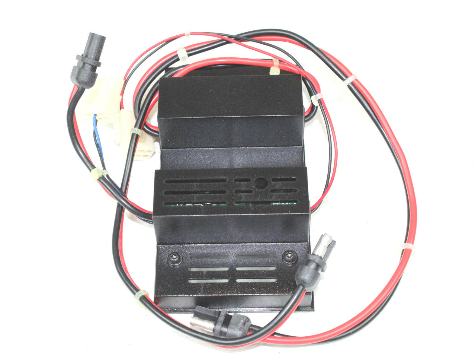
The optional HLN9455A Battery Revert Kit (photo) was a common option for many base stations and was included on the specification sheets for the GR300, GR1225, RKR1225, GR400, GR500, CDR500 and CDR700 repeaters. The HLN9455A is a small module and includes a cable harness that connects between the power supply and the radio. The other harness section connects to an externally mounted user-supplied 12 volt radio battery (or a 12 volt site battery). The 6880905Z74-A manual could not be ordered, it was only available as part of (and was packed with) the kit. The circuit description / theory of operation section is worth reading. There is more to this unit that first appearances suggest, I especially suggest you read the pages that describe how to size the backup battery.
The battery revert kit board functions as a power fail switchover / battery monitor / battery trickle charger module that switches the radio to the battery during a power failure and keeps it charged with a 300 milliamp (maximum) trickle charger. Note that the unit was designed for lead-acid batteries and the charger will not work properly with NiMH or LiOn batteries. The manual stresses that the HLN9455A is NOT intended to be a battery charger, just a maintenance trickle charger, and the current level drops to under 25 milliamps on a fully charged battery. The trickle charger voltage is set by R70, a 5K Ohm potentiometer. For longest battery life you should determine the resting voltage of your new battery when fully charged and set R70 to that voltage +0.1v / -0.0v.
The battery revert kit board generates an "On Battery" output signal (active low) that can be connected to the R1225 accessory connector, and optionally in parallel to an external repeater controller. If enabled in the R1225 RSS / CPS programming the "On Battery" signal causes a "beep" signal to be generated on the transmitter when you are running from the battery. The actual "beep" is internally generated by the R1225 module, not by the battery revert kit board (like it was on the Micor station version). The Kit also supplies a "Low Batt" output (active low) that could also be fed to an external controller - which could be programmed to announce the fact that the backup battery was low in voltage / almost dead.
The HLN9455A Battery Revert Kit can easily be built from the schematic and parts list – the manual does an excellent job of describing how and why each portion of the circuitry does what it does. If you homebrew your own you might want to simplify your version and leave out the battery maintenance charger… instead use an external good quality multistage charger.
Programming the R1225 module, the GR1225 or RKR1225 repeaters:
The HVN9054 RSS / CPS will program the full duplex R1225 module, the P1225 handheld and the M1225 mobile - but the three devices are totally different animals! The only common element is the programming software. Also, the 20-channel M1225 models can do channel steering, some of the 4-channel M1225 units can and others cannot (depends on the firmware). The mobile and the repeaters use a standard RJ-45-style Motorola mobile programming cable, the handheld uses a different cable. The HVN9054 RSS / CPS will run under any 16-bit or 32-bit Windows, such as 3.1, 95, 98, XP or 7, your author has not tried it on Win 8 or 10 but it should work on 32-bit versions as long as you have a real serial port or an FTDI based USB to serial adapter. The HVN9054 RSS / CPS will NOT run under any 64-bit Windows. If anyone knows a way to enable 64-bit Windows to run XP vintage software please let the author know!
The HVN9054 RSS / CPS was issued in at least two versions (you really want version 4). Version 3 runs under Windows 3.1, 95 and 98 and only "knew" about COM1 through 4. Version 4.0 (HVN9054E) fixed a few bugs, added support for COM1 through COM16, and added the ability to run under XP. Once you write to the radio with Version 4 you cannot go back to Version 3 (you get the classic "code plug too new" error). If you try to run two copies at the same time you will get an error.
The HVN9054 RSS / CPS has a configuration parameter called "Archive" which determines where the stored codeplugs are saved. I set it to position an Archive directory under the RSS directory. The RSS identifies the codeplugs with a leading letter and the number 780 (the Accounting Product Code or APC). The codeplugs for the M1225 mobiles were prefixed with M780, the codeplugs for the P1225 portables were prefixed with P780 and the repeater codeplugs (R1225, GR1225 and RKR1225) were prefixed with R780.
The RSS / CPS manual (68-80904Z93) is part of the HVN9054 kit and cannot be ordered separately. If anybody has a paper copy of the 68-80904Z93 manual we would like to scan it and post the PDF here (or if someone else has already PDF'd it please email it so we can post it here).
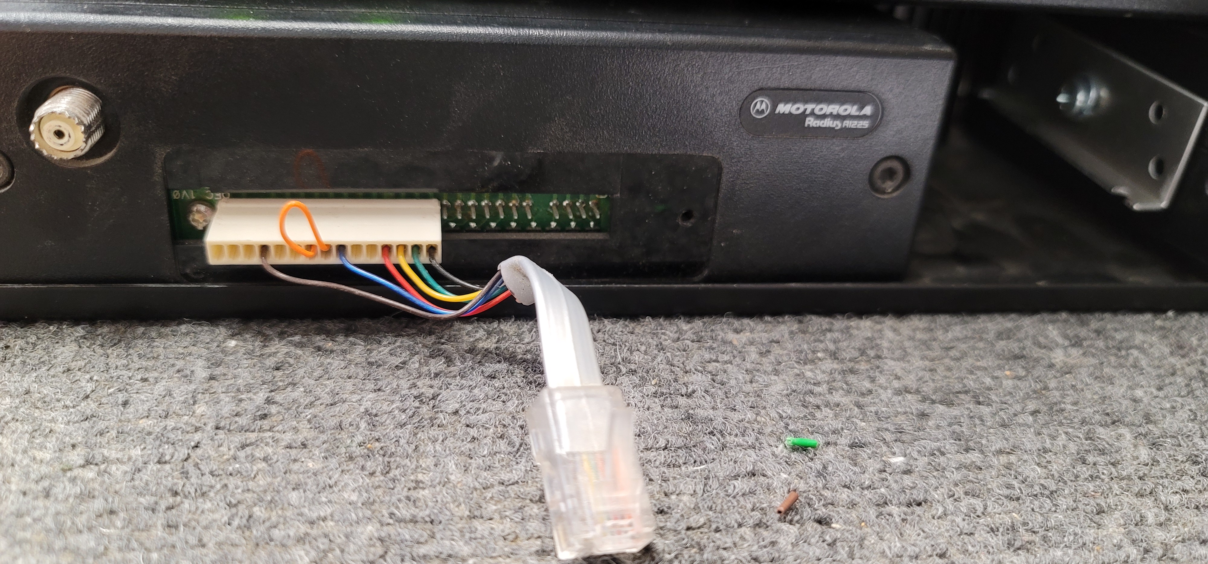
There are pages at this web site that cover using the RIB and RSS / CPS in detail. The R1225 programming is usually done through the microphone connector, which is part of the HLN9514 control panel described above. One of the authors R1225 modules showed up with an interesting microphone and programming adapter. It looks like someone added on to the white plastic power jumper mentioned above… and the result could be homebrewed. Photo 1 Photo 2 photo 3 - in use. The R1225 can be programmed for up to 16 channels. When programmed for only one it will operate just fine without the HLN9514 control panel connected, just jumper the power switch pins.
According to the R1225 service manual, the receiver's front end has three PIN diode switched bandpass filters following the first RF amplifier. All three have 1 dB bandwidths of 10 Mhz, centered on 151 MHz, 161 MHz, or 171 Mhz. So the first filter covers 146-156 MHz, the second 156-165 MHz and the third 165-174 MHz. When you are programming the R1225 and in the mode screen of the RSS / CPS you can highlight RX frequency field then hit shift-F3 to override the automatic bandpass filter selection for receive. This hidden trick appears to allow override of automatic (by the RSS) selection of the correct Bp filter which likely would be chosen based on the receive frequency. The UHF model is similar, with bandpass filter ranges of 444-454 MHz, 454-464 MHz, and 464-474 MHz.
There is no tune-up required on the R1225 module itself. The RX front end is varactor-tuned by the CPU to optimize the RX sensitivity.
The transmitter has a similar trick. You can highlight the TX frequency and hit shift-F2. This will allow you to select the offset frequency. This last option is more useful for the M1225 mobile and the P1225 handheld than on the R1225 repeater.
The HVN9054 RSS / CPS will program the R1225 radio out-of-band with the "shift-key" method that is covered on the RSS / CPS page at this web site, or you can hexedit the RSS / CPS. Other web pages call the R1225 "out-of-band-unfriendly" since it frequently hangs when shift-key manipulated like GM300 or Maxtrac RSS / CPS when entering out-of-band frequencies. The trick is to use the Tab key to manuver into a frequency entry field, then use the shift key trick to enter the frequency, then use the Tab key to advance to the next field. With this RSS / CPS you do not want to use the Enter key while entering the out-of-band frequency!
The programmable parameters of the R1225 module allow it to be configured as a base station, as a repeater or as a non-repeating full duplex radio (i.e. as a link radio or as a repeater when connected to an external controller). Receive and transmit performance will suffer if you program the unit too far out of the design range of 146-174 or 444-474 MHz. Using a VHF R1225 on a 145 MHz repeater pair will have less receiver degredation that using a UHF one on a 440 MHz receive frequency. Setting the RF power output level is done with the "Tune" feature built into the RSS / CPS (there is no separate "tuner" program). The transmitter is NOT happy if it sees a high SWR.
Your author had one case where a high SWR caused an R1225 UHF transmitter to go into audio oscillation (it sounded like knobby off-road tires rumbling on a asphalt road at about walking speed or a little faster). So now part of his R1225 bench test procedure is to test the transmitter into a deliberate 3:1 SWR load. A simple way to create that SWR is to use a type N "Tee" fitting and two 50 Ohm loads plugged into the female ends of the T.
Eric Lemmon WB6FLY (SK) reported once that:
A local hospital had a GR1225 repeater come back from a radio shop with the TX and RX cables to the internal duplexer reversed, and it wouldn't work very well. It tested fine on the service monitor, but the shop tech got confused about the "HIGH" and "LOW" labels on the notch duplexer. The ports should have been labeled "REJECT HIGH" and "REJECT LOW", with the former going to the TX output on the R1225 and the latter going to the RX input on the R1225. If the R1225 is a high-power (25-50 watt) model, it is possible that operating the transceiver with a mis-tuned notch duplexer can burn out the protection diodes in the RX front end.
When a service tech works mostly with BpBr cavities, it is a common error to tune the screws for the pass frequency instead of the notch frequency.
The R1225 PL / DPL:
The R1225 is a rare beast in the Motorola product line… it is not limited to a hard coded table of PL tones or DPL codes. As you program the "Mode" you program teh receive and transmit frequencies, and both can be programmed for "CSQ", "TPL", "DPL", and "INV DPL". If you select TPL you get a dropdown list of can type in any PL tone to the tenth of a cycle or use weird tones. Or strange DPL codes, even inverted. The only commercial radios that I know of that can do that are the R1225 modules, the HT750 / 1250 / 1550 series handhelds, a few Kenwoods and most of the Icom commercial radios. There are probably others. I suggest that if you use DPL that you stick with the "standard" list of codes. Using strange DPL codes can generate an offset on the transmitter frequency - this is caused by an unbalanced distribution of ones and zeros, and that can make the transmiter appear to be off frequency, which can cause the receiving radio to distort the audio which can cause receiver squelch problems. A list of the standard DPL codes (both normal and inverted) is at the bottom of this page.
The R1225 Repeater Courtesy Beep:
The Courtesy Beep feature of the R1225 built-in repeater controller is accessed on the "Radio Wide" tab, with a checkbox labeled "Courtesy Over Beep". There are no programmable parameters, it's either on or off.
Configuring The R1225 Internal Repeater IDer:
Some user radios have a "slow" squelch… i.e. it takes a measurable amount of time to open. This design fault in the user radio can mask all or part of the first Morse character of any ID you program into ANY repeater controller, not just the R1225. I suggest delaying the ID by programming a delay (dead carrier) perhaps by placing a space character (or two or three ) into the front of the ID string to avoid missing the first dah or the first couple of dits when the ID'er keys the PTT line from an idle state. This is the voice of experience.
The R1225 built-in basic repeater controller has an MCW identifier function. It is accessed by way of the "Radio Wide" tab, and then a checkbox labeled "CW ID Signaling". When that checkbox is checked a new tab with several fields appears. The first field selects one of four IDer audio frequencies (750 Hz, 1000 Hz, 1250 Hz, and 1500 Hz (no, you can't pick your own). Then there is a selector for the mode: "Only w/Rep.Activity", or "Always". USA amateur radio operators will want the first mode, the second mode is a beacon. Then there is the "CWID" field. This is your identifier callsign – you have 12 characters and it understands both space and "/". The CW ID interval can be either 10 or 15 minutes (no, you can't pick your own). The ID can be routed to the internal speaker or not, the latter mode was used in the Base Station mode (picture a shopping mall rent-a-cop dispatcher, the GR1225 could be the dispatch base station as well as the repeater). A checkbox for "PL Strip" allowed sending the ID with or without the transmitter PL tone or DPL code. Personally, I always check the "PL Strip" checkbox. The "Interupptible by PTT" checkbox allows an impolite (unchecked) or polite (checked) mode: You want the impolite mode for your amateur or GMRS repeater (unchecked) to send the ID. Checked is the "polite" mode which waits for an idle channel to ID… but it is too polite… If the squelch opens during the ID it stops the ID and waits again for an idle channel. Under busy channel conditions it might never send a complete ID. A repeater in the amateur service requires a complete ID every 10 minutes of use so your author either unchecks the "Interupptible by PTT" checkbox or uses an external controller.
The R1225 Module Connections:
As mentioned above the R1225 front panel has a single-row 27 pin connector (with standard 1/10 inch spacing) on the face of the radio. The schematic diagram and the cabling breaks it into two connectors: J8 and J9. Cable swapping is prevented with each of the female ribbon connectors has a plastic peg (block) in one pin position and the connector on the front of the module has that pin missing.
| R1225 Front Panel Connector Pinout The left 15 pins are referred to as J8 on the Logic Board schematic and connect to the the volume control and microphone jack board in the HLN9514 control panel. |
||
| Pin | Description | Application / Notes |
|---|---|---|
| 1 | Volume Control (high side) | |
| 2 | Volume Control (wiper) | |
| (3) | (no physical pin) | The ribon cable connector has a block in this position to prevent swapping cables. |
| 4 | Handset (earpiece) Audio | Connects to pin 8 of the microphone jack. This can be used as RX repeat audio. |
| 5 | Speaker (-) | See accessory connector pin list below for pin 1 |
| 6 | Speaker (+) | See accessory connector pin list below for pin 15 |
| 7 | Switched +12vDC input | Pin 8 is jumpered to pin 7 to switch the unit on. |
| 8 | +12vDC | This is unswitched +12 volts from the + power input on the back of the unit. This pin is not fused. DON'T accidentally ground it, you WILL wish you hadn't. |
| 9 | SCI+ | This connects to pin 7 of the microphone jack and is used to program the unit. |
| 10 | Relay | This is the +12vDC voltage intended to drive an antenna relay. You can connect a LED here (with a series resistor) to indicate PTT, but there is a pin for a "real" TX LED on the other connector. Another use for this pin is to power a small 12vDC fan pointed at the heat sink. |
| 11 | Spare / No Connection | |
| 12 | Ground | This connects to pin 4 of the microphone jack plus other places. |
| 13 | PTT | This connects to pin 6 of the microphone jack. |
| 14 | Microphone Audio | This connects to pin 5 of the microphone jack. |
| 15 | Microphone Hookswitch | This connects to pin 3 of the microphone jack. |
| R1225 Front Panel Connector Pinout The rightmost 12 pins are J9 on the Logic Board schematic and connect to the display / button board of the HLN9514 control panel. |
||
| R1225 Front Panel Connection (J9 on Logic Board) | ||
| Pin | Description | Application / Notes |
|---|---|---|
| 1 | RX LED | The radio pulls this pin to ground to illuminate the LED. This is an open collector and is NOT capable of driving a relay. |
| 2 | Display Enable | This is a logic level from the repeater that enables or disables the display. |
| 3 | TX LED | The radio pulls this pin up to +12vDC through an 810 ohm resistor to illuminate the front panel LED for PTT indication. This pin will NOT drive a relay (use pin 10 of J8 above). |
| 4 | Buttons | This is a stepped DC voltage output from the control panel. When each of the 5 front panel buttons is pressed it delivers a different DC voltage into this pin. An A-to-D circuit in the repeater module measures the voltage and that is used to decide which button was pressed. |
| 5 | Repeater Enable LED | This LED is fed by 5 volts through 270 ohms and this pin pulls to ground to illuminate it. |
| 6 | Spare / No Connection | |
| 7 | Spare / No Connection | |
| (8) | (no physical pin) | The ribbon cable connector has a block in this position to prevent swapping cables. |
| 9 | +5vDC | This pin delivers power to the front panel for the LEDs and buttons. This pin is NOT fused, if you accidentally ground it you will melt traces. |
| 10 | Serial Data | Drives the 2-digit 7-segment display plus the "Monitor" and "Option" LEDs. |
| 11 | Serial Clock | |
| 12 | Ground | |
If you have the HLN9514 control panel plugged in then you will have this microphone / programming connector:
| Microphone Connector Pinout Note that the pins are numbered backwards – from the right to the left. |
||
| R1225 Front Panel Connection (J11 on the Control Panel Schematic) | ||
| Pin | Description | Application / Notes |
|---|---|---|
| 1 | +8 v DC, up to 500ma | This is sourced from a dedicated MC78M08 regulator mounted on the microphone and volume control circuit board in the control panel. |
| 2 | Spare Pin | |
| 3 | Hookswitch (to ground) | |
| 4 | Ground | |
| 5 | Microphone Audio In | |
| 6 | PTT | |
| 7 | SCI+ | Programming |
| 8 | Handset | Earpiece Audio Out |
The 16-Pin Rear Accessory Connector:
The R1225 module has a internal controller that supports a number of programmable features. Here is a short-form description of each pin on the rear accessory connector (referred to as J3 on the schematic). A number of the pins can be programmed for various functions. Several pins can be programmed as either input or output. Default settings listed below are what a factory new radio would be programmed to; what you find in a new-to-you radio will depend on previous programming.
 The pinout of the 16-Pin rear accessory connector |
||
| Pin | Description | Application / Notes |
|---|---|---|
| 1 | External Speaker (-) | CAUTION: This is a bridged-type (floating) output. Neither pin 1 nor 16 is ground or can be grounded. Connect an external 8 Ohm speaker to pins 1 and 16. Operation of the speaker is dependent on the presence of a volume control, which is part of the optional external control panel. |
| 2 | External Microphone Audio | Input impedance: 500 ohms. 80 mV rms at 1 kHz results in 60% deviation. This path is enabled when the external Push-To-Talk line (pin 3) is active (grounded). |
| 3 | External Push-To-Talk in or out | This pin is pulled high inside the repeater to +5 volts DC via 9.6k Ohms. Key the transmitter by pulling this pin low (less than 1.8vDC), this action also enables pin 2. This pin is also pulled low via a diode when the front panel mic PTT is pulled low. This diode allows an accessory to sense an active front panel microphone PTT. CAUTION: Some external controllers have a pull-up resistor that pulls this PTT line up to +12 volts. Before you connect your external controller to this line you will want to measure the external controller in idle (unkeyed) mode. You might have to add some external interfacing circuitry. |
| 4 | Programmable Output | Defaults to Null. Provides an active high through a transistor to the +13.8 volts DC battery supply. Refer to the "Programmable Pins" section below. |
| 5 | Transmitter Flat Audio Input | Input impedance: 35k Ohms. 150 mV rms for 60% deviation. May be programmed using RSS / CPS to bypass the limiter. |
| 6 | Programmable Input | Defaults to Null Input. Refer to Refer to the "Programmable Pins" section below. |
| 7 | Ground | |
| 8 | Programmable Input / Output | Defaults to COR carrier detect output. Refer to the "Programmable Pins" section below. |
| 9 | Programmable Input | Defaults to Null Input. Refer to the "Programmable Pins" section below. |
| 10 | Programmable Input | This pin has two functions: either Null Input or Repeater knockdown (enable/disable). This pin defaults to Null Input, but may be programmed for repeater setup / knockdown. Activating this pin when in the Repeater Mode knocks down (disables) the repeat function and places the unit in Base Station Mode. The front panel "RPT EN" pushbutton is overridden by pin 10. |
| 11 | Rx Audio Output | Output impedance: 560 Ohms. 330 mV rms (at 1 kHz if de-emphasized) at 60% deviation. Minimum load resistance: 5k Ohms. Default is de-emphasized, PL filtered, and squelch muted. May be programmed for flat and unmuted using RSS / CPS. This pin can feed an external PL or DPL decoder when set for flat and unmuted and can also be used for repeat audio by enabling the de-emphasis function of the audio input on the external repeater controller. |
| 12 | Programmable Input / Output | Defaults to Null Input. Refer to the "Programmable Pins" section below. |
| 13 | Switched A+ Sense | +13.8 volts DC source for accessories when the radio is turned on. Note that the maximum current available is 1 amp on one document and 0.5 amp on another. CAUTION: Accidentally shorting this pin to ground with power applied will vaporize circuit board traces. |
| 14 | Programmable Input / Output | Defaults to Null Input. Refer to the "Programmable Pins" section below. |
| 15 | Internal Speaker (+) |
There is a jumper (JU501) inside the R1225 that shorts pins 15 and 16 of the accessory connector to enable the speaker pins on the front of the R1225. If jumper JU501 is open (the factory default state), you need to jumper pin 15 to pin 16 to enable the speaker. NOTE: If the HLN3145 Public Address and Speaker A/B Switch kit is used, then jumper JU501 must be removed if it is desired to mute the internal speaker when the toggle switch is in position B. |
| 16 | External Speaker (+) | See as pin 1 above. The same caution applies. See also pin 15 above. |
Expanded Accessory Connector Programmable Pins:
Pins 4, 6, 8, 9, 10, 12, and 14 on the accessory connector are programmable. The function of each pin can be assigned using the RSS / CPS. Information on the available functions and how to program them is contained in the RSS / CPS help screens and in the files in the Appendices section of the manual. The programming of these pins is very similar to the GM300.
Pin 4 is an output only. This output pin actively pulls high to the +13.8 v DC supply using a transistor, otherwise it is pulled low with 10k Ohms. Maximum current is 0.25 Amps, which is enough to drive the coil of a small relay (make sure it has a backwards diode).
Pins 6, 10, and 9 are inputs only. They are normally pulled high inside the radio to +5 v DC via 4.7k Ohms. To activate any of these input pins, it should be pulled low to within +0.7 v DC of ground by external circuitry.
Pins 8, 12, and 14 may each be programmed as either an input or output. If programmed as an input, the pin is pulled high to +5 v DC via 4.7k Ohms. To activate the input, it should be pulled low to within +0.7 vDC of ground. If programmed as an output, the pin is normally pulled high to +5 v DC via 4.7k Ohms. When active the output is pulled low through a transistor. Maximum sinking current is 50 mA.
The R1225 radio module, like the GM300, supports "channel steering" through the accessory connector. To use the channel steering you need to program several of the general-purpose I/O pins (6, 8, 9, 12, and 14) for "Channel Select". The number of pins you program for channel select determines how many remotely selectable channels you can access with a binary selection mechanism. If you release all of these lines, the pins are pulled high and the radio reverts to the channel selected by the front panel (if present). Each channel steering pin can be programmed for active high or active low (the default). Two pins gives you 3 selectable channels, three pins gives you 7, four gives you 15 (unlike the GM300 the max is 16). Each channel select pin turns into a binary coded input that allows you to select any of the possible 16 channels by grounding the appropriate input lines (assuming you've programmed the pins for active-low inputs). Channels 1, 2, 4, 8, or 16 may be selected by grounding Channel Select line 1, 2, 3, 4, or 5 respectively. All other channels are selected by grounding multiple select lines in a binary pattern. If you select a channel that does not exist (example: 10 channels programmed and you select channel 12) the radio reverts to the channel selected by the front panel.
Interfacing to an External Controller:
First of all, the R1225 has an internal controller and that needs to be disabled in the programming software if you are going to use an external controller (i.e. configure the unit as a dumb full duplex radio). The actual interfacing is done through the 16 pin accessory connector. The operation and programming of the programmable pins is very similar to the GM300. As said above, what you find programmed in your new-to-you radio may not be the defaults mentioned.
When your author builds an interfacing cable for the R1225 (or GR1225 or RKR1225) he starts with a cable kit from Kurt Meltzer KC4NX who sells on eBay as "mre1032". He can also be reached at mre1032 //at// yahoo //dot// com. His Cable #143 is a premade three foot long 8 conductor (plus shield) cable. I prefer the unbuilt Cable 143K (K=kit) so I can customize the pinout for each application as the pre-built Cable #143 does not connect to pin 13 (DC power out), also it puts Red on pin 6 and Violet on pin 4. The wire colors listed below are how I use his kit, not from his premade cable. If 5 conductors (4 conductors plus shield) will fill your needs then use his Cable #63K. Cable #103K (3 ft) or Cable #106K (6 ft) offer 8 conductors.
If you need more than 8 conductors then send Kurt an email, he has higher conductor count cable stock available.
Disclaimer: I have no relationship with Kurt other than as a satsified customer. I just have 70+ year old eyes and have big fat fingers that have difficulty crimping the accessory connector tiny pins onto the individual wires, and then getting the pins into the plastic body rightside up.
| Pin | 143K Color |
Description |
|---|---|---|
| 2 | White | Repeat (speech) audio from the external controller to the R1225 transmitter. |
| 3 | Black | PTT from the external controller to the R1225 transmitter. |
| 5 | Blue | External non-speech (flat) audio input to the R1225 transmitter. This pin can be programmed to bypass the limiter. Typical use is for a PL / DPL encoder, P25, DMR, LTR or paging data, etc. For example, the Scom 7330 repeater controller has a PL encode audio output separate from the repeat audio output. That PL encoder audio would be connected to this pin. |
| 6 | Programmable Input. | |
| 7 | Bare shield | Ground |
| 8 | Brown | Programmable Input / Output - Defaults to output the COR / Carrier Detect logic signal (active low). |
| 10 | Programmable Input. See note above. | |
| 11 | Green | Discriminator audio or repeat audio from the R1225 receiver to the external controller. The factory default for this pin is de-emphasized and squelch muted. This pin can deliver discriminator audio by programming for flat and unmuted, like what you would need for an external PL or DPL decoder. When programmed for flat and unmuted you will need to de-emphasize the audio externally. Some amateur radio repeater controllers offer this feature as a jumper option. Scom is one. |
| 12 | Yellow | Programmable Input / Output. Factory default was Null Input, however could be programmed as an output (like PL Decode). |
| 13 | Red | Switched + DC voltage out. Could be used to power an external repeater controller. Note: The maximum current available is 1 amp on one document and 0.5 amp on another. Caution: Shorting this pin to ground can melt circuit traces insde the R1225. |
| 14 | Programmable Input / Output. Factory default was Null Input, however could be programmed as an output. | |
| 15 | Jumper | Connect 15 to 16 to enable the speaker (or short JU501). |
| 16 | Jumper |
Manuals and other Literature:
The User Manual for the R1225 is 6880904Z89. The "R1225 Safety/Licensing Guide" was 6880905Z34, the "R1225 Accessory Sheet" was 6880905Z51. All three were parts of Manual Kit HLN9535 and could not be ordered separately. If anyone has PDFs please email the file to us. If you have a paper manual then may we borrow it and scan the relevant sections?
The R1225 radio module service manual is here: 6880905Z53-O.pdf, when it was available from Motorola Parts it was in the US$13 price range. This PDF is an 8.5 inch wide scan - all of the pull-out pages are chopped into thirds. If anyone would like to scan each of the wide pages as a single wide scan then the page maintainer would be happy to replace the chopped up pages with the full width scan pages.
The first 85 pages in the PDF linked above are update / replacement pages. Page 86 of the PDF is actually the first page of the actual manual.
Page 96 of the PDF is the specifications page. It does not mention the existence of the low power models. It shows the transmitter DC current is 14 amps for VHF and 12.5 amps for UHF. The actual measured current drain for the low power UHF unit is under 4 amps at 9 watts. At the time the page maintainer is writing this paragraph he does not have a VHF low power unit to measure.
If anyone has a later manual (i.e. 6880905Z53-A, 6880905Z53-B, etc) your page maintainer would appreciate hearing from you.
If your repeater is a GR1225 tabletop unit, you also need the 6880904Z90 manual, which was also about $13. It contains the the GR1225 cabinet and other GR1225 specific information. The control panel and power supply sections are also in the RKR manual below. If anyone has a PDF please email the file to us.
The RKR1225 rack mount repeater manual is here: 6880907Z10-O.pdf. When it was available it was about $36.
The GR400 rack mount and GR500 wall mount packaged repeaters were originally supplied with two GM300 family mobile radios, and could be upgraded for narrowband by a field-installable kit (HLN3100) that replaced both of the GM300s with a single R1225 module. The kit included two paper manuals, the first was the R1225 radio module service manual 6880905Z53 above, the second was the 6880905Z54 manual that is here: 6880905Z54-O.pdf.
The manual for the RSS / CPS for the R1225 / GR1225 / RKR1225 is 68-80904Z93. That manual was part of the HVN9054 software kit and could not be ordered separately. If someone has a PDF of it please email it to us. If you have a paper manual then may we borrow it and scan the relevant sections?
The official accessories list for the GR1225 is here. The usual sources didn't have it (after all the R1225 is about 25 years old at the time of this writing) but I found it on the web.
Motorola had a service bulletin for the R1225 that specifically stated that for high duty cycle operation the R1225 high power repeater models were to be set to operate at 25 watts maximum output from the transmitter, not from the duplexer output.
Does anyone have a copy of that service bulletin?
One note, there is a clamping Diode CR1 which limits the drive into Q1 the first amplifier, if you find this blown or shorted, then you may have an isolation problem with your duplex setup.
Features, Issues, Missing Information, Service Tips and Parts:
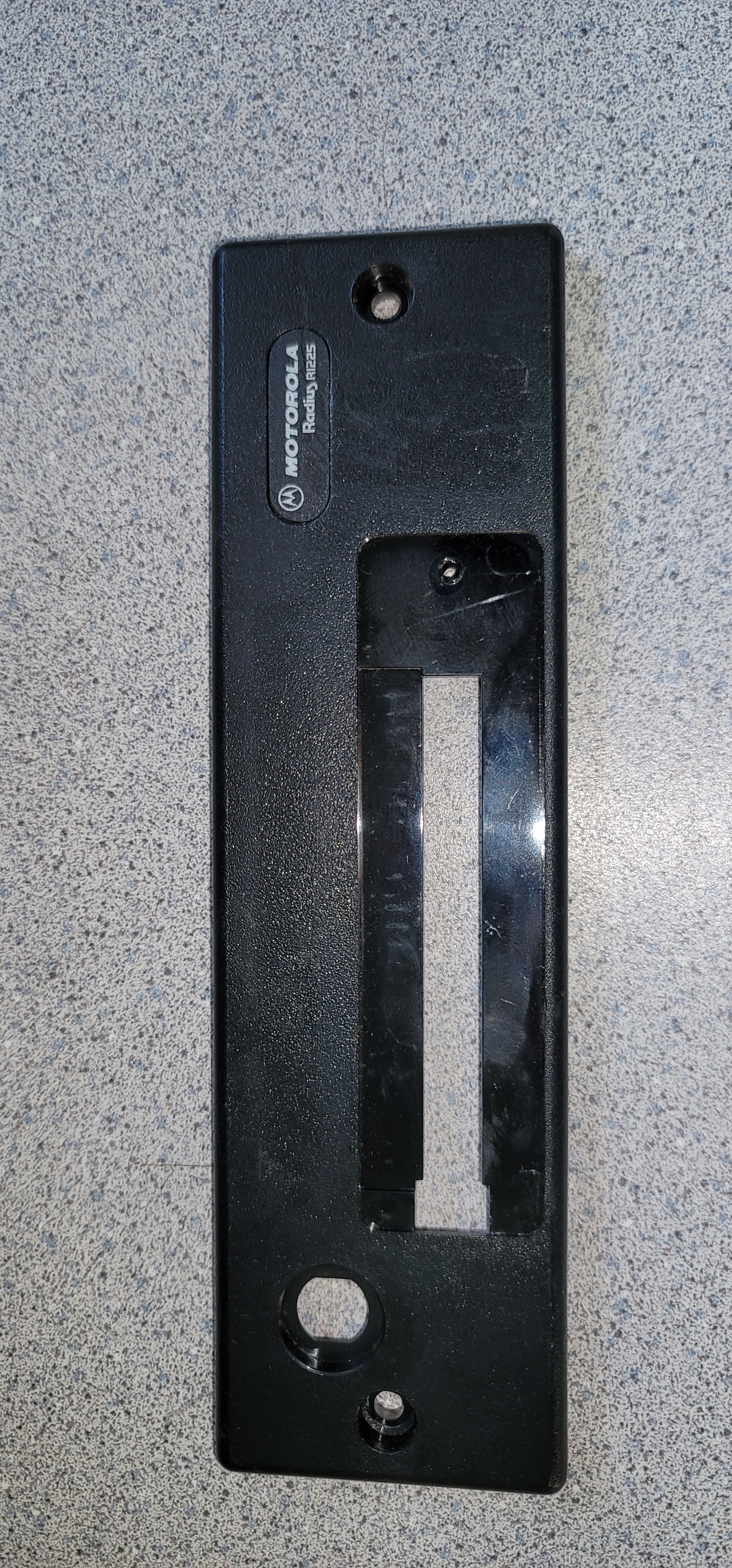
Two things missing from the R1225 module front panel are a power-on LED and a transmit LED (both of which are on the HLN9514 control panel).
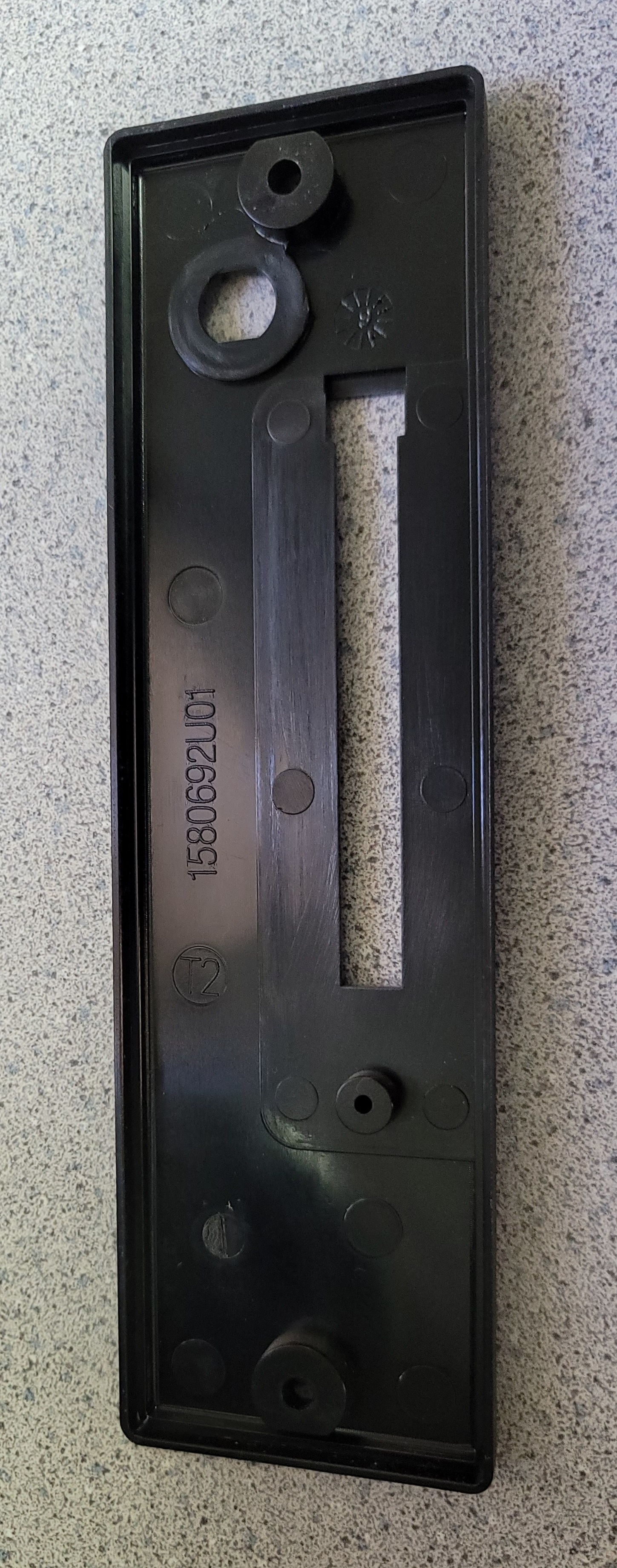
The module front panel - the cosmetic faceplate - is part number 1580692U01. Front photo Rear photo
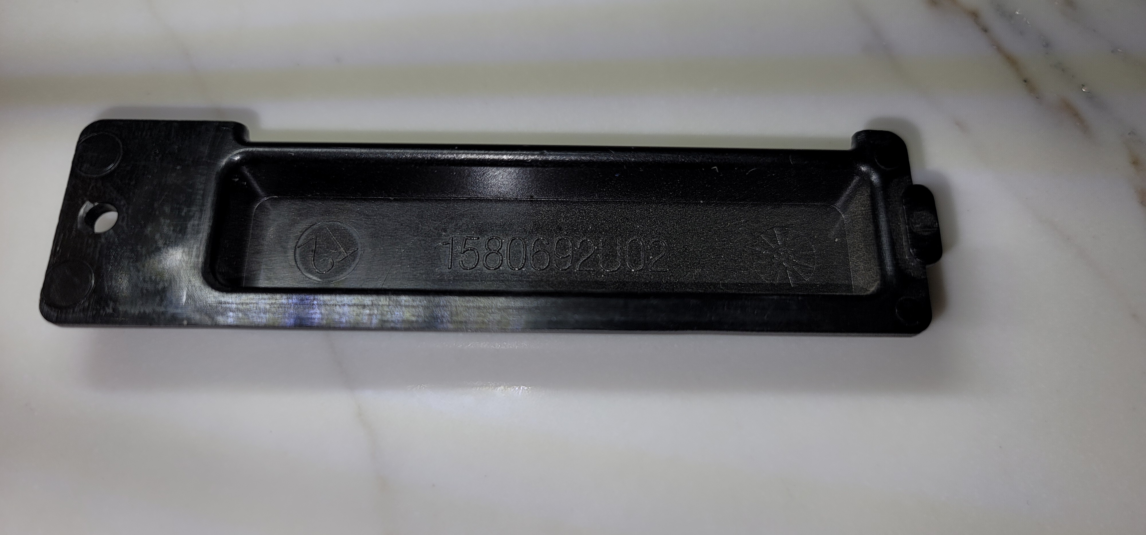
The protective cover for the front panel connector (for the R1228 module control panel connector pins) is 158062U02. Front photo Rear photo
Microphones: The R1225 does not like the newer microphones, like those made for the CDM radios. When you plug one in the radio goes into constant transmit.
Use a microphone made for a Maxtrac / Radius LRA / GM300 / GTX radio and you'll be fine.
Several of the pre-packaged repeater models do not have a speaker or a speaker output connector (the RKR1225 is notorious for this). Adding a speaker, or at least an 1/8 inch / 3.5mm jack for an external service speaker can be a useful modification at a minimal cost. If you don't have the HLN9514 control panel connected don't bother as you won't have any receiver audio on the speaker pins (because without the control panel there isn't a volume control in the circuit).
The HLN9514 control panel contains two circuit boards, one has a 2-pin speaker connector, and as mentioned elsewhere a speaker jack could be added to the control panel faceplate.
Service tip 1:
If your high power unit keys up with full 45 watts for a moment and then drops off (and it's not due to high SWR, i.e. test it using a dummy load), and swapping a known good PA onto the radio does the same thing, and running the "new PA" calibration procedure does not fix it then look at Q451… it's Motorola part number 48-00869619, a PNP, 40V, 4A, TO-225 transistor on the heatsink near the 16 pin accessory connector. I've also found a Motorola transistor labeled 81142 in that position. Either can be replaced with an MJE371 (available from Digikey, Mouser and many others). Adjacent to Q451 is Q401, and is the same device.
Service tip 2:
If you swap PAs then you need to run the calibration procedure in the service manual. The PA settings (which are stored in the Logic Board) are not always the same as what would be correct for a different PA.
Service tip 3:
The low power and high power R1225 bodies are the same, they were programmed as a low or high during manufacture. They control the PA deck differently. It should be possible to reset the model number and thereby allow converting a low to a high and vice versa but your author has not figured out how to do that. As an example your author swapped a low power PA onto a factory high power unit. Instead of the advertised 1 to 10 watts the new PA maximum output was 3 to 4 watts instead of 10 to 15). How do you fix that?
The author received an envelope (without a return address) at his QRZ address of record… it had a second generation xerox of an R1225 parts list with industry standard part numbers. He made a web page from it... see this page (Opens in a new browser tab). There is a "print" function in the upper right corner of that page.
Some R1225 RF Power Amplifier Physical Concerns… and the Fix:
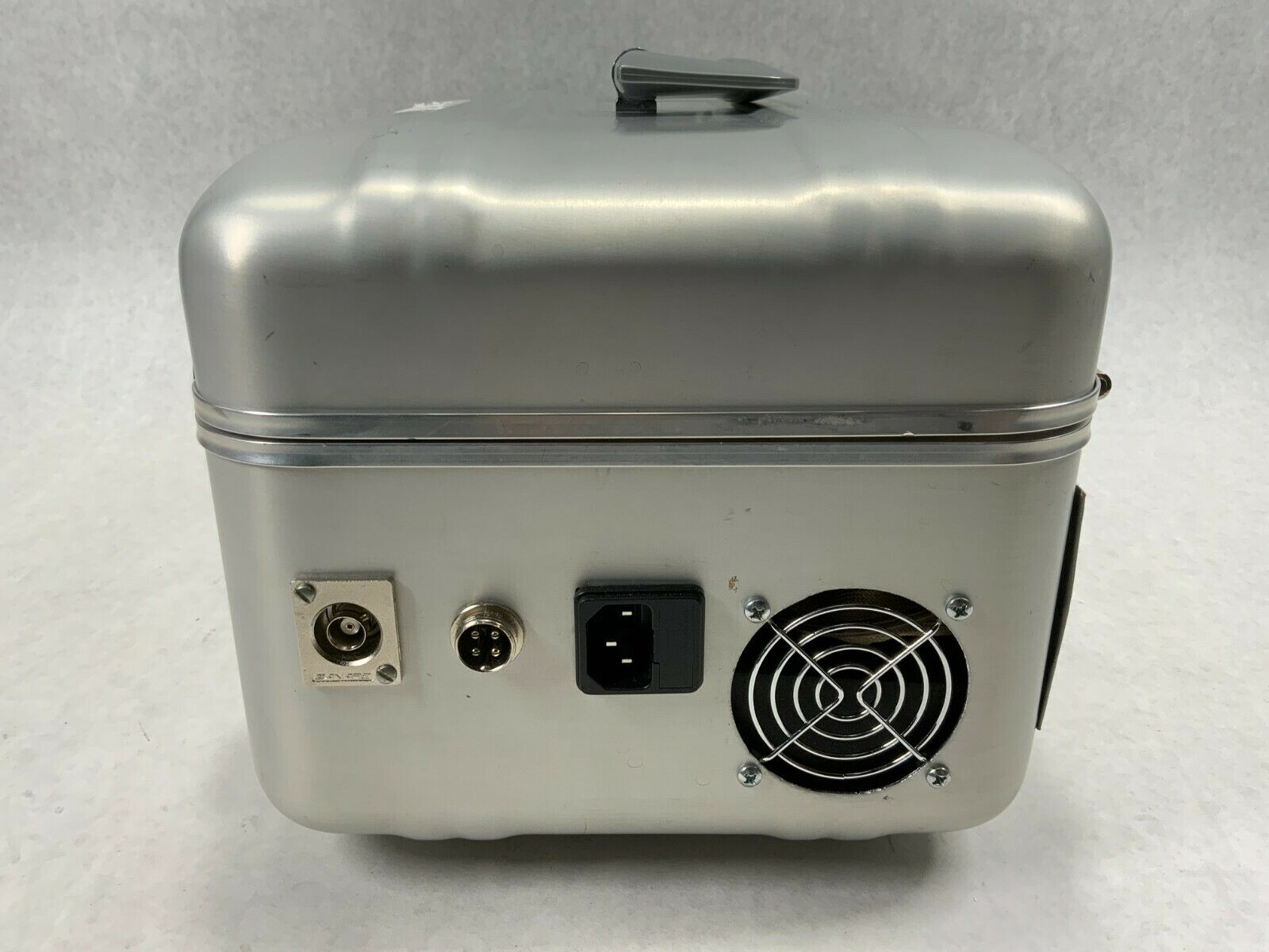
Fan(s) and the DC power supply:
The GR1225 / GR400 / GR500 / RKR1225 packaged repeaters have a fan integrated into the rear of the repeater housing for cooling (see the photo at the top of the page). The housing fan and air flow ducting that Motorola provided is inadequate for a high power unit on a busy channel. The stock factory housing fan is temperature controlled, some have been found with regular fans (obvious field replacements). Depending on the run time all fans should be inspected for wear since if the fan fails the high power PA can self-destruct due to it's own internally-generated heat. The power supply used in a GR1225 or RKR1225 could be one of a few models, some have an internal fan. Your author has had a few power supply fans go bad. Several GR1225s and RKR1225s have been found in the field connected to a site 12 volt battery system with the internal power supply disconnected or removed, and with the 12vDC fan(s) relocated to the heat sink. If you need a new fan this is a good one, but you will have to change the connector.
The PA itself:
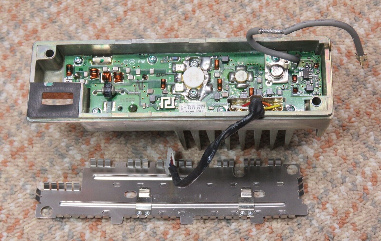
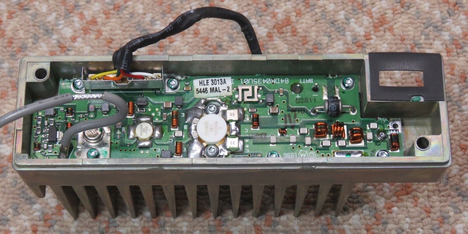
The R1225 PA (low power or high power) is unique… while the inside of the PA looks very much like a GM300 PA circuit board, it's not. The GM300 PA has a a 6-pin control cable and two coax cables (one for the incoming RF from the exciter and the second cable to feed the receiver). The R1225 has the same 6 pin control cable but only one coax (for the RF from the exciter), there is no Transmit / Receive switching.
R1225 high power UHF PA photos: Photo 1 Photo 2 Photo 3 Photo 4 Photo 5 Photo 6
The design and manufacturing process of the R1225 high power PA was THE weak spot in both VHF and UHF R1225 product line. Motorola's own data sheets / specifications sheets / manuals say 25 watts continuous, 50% duty cycle at 45 watts (UHF, or 50 watts VHF). That duty cycle works out to 5 minutes of talk and 5 minutes of no talk. In which universe does a commercial user not talk? (it's hard enough to get some of them to release to listen). This intermittent specification is a marketing dream. And it didn't help that Moto engineering specified the wrong thermal sensor for the fan - it turned on at a too-high temperature, and was positioned too far from the heat source (the final transistor). You want that fan running long before the heat sink fin temperature hits 125 degrees F… By that time the PA transistor is way hotter.
If you have a high power unit and want it to last with any measurable duty cycle then you need to set the transmitter to 25 watts plus relocate the case fan sensor to right over the PA transistor. Look at the rear heat sink, you will see the stud for the power transistor. Position the sensor as close to the stud as possible. Some R1225s that I found didn't have any sensor on the heat sink; the case fan was wired in parallel with the fan inside the power supply, or to the power supply directly (someone jumpered out the fan thermal sensor and ran the fan full time). Others had a 12 volt DC fan connected to the antenna relay output pin on the front panel connector (pin 10) so the fan was controlled by the PTT.
If you have a high power R1225 running at any duty cycle and your fan fails then the odds are better than 7 in 10 that you will kill your power amplifier. Personally, I'd add another fan (or two smaller ones) on top of the heat sink, with a sensor for the new fans between the heat sink fins right on the transistor. And I'd add an additional thermal switch that would fire up an extra fan blowing on the heat sink… And trigger a digital input on the repeater controller and that would announce an overtemperature problem.
If you have a high power R1225 in service then do not set the RF power level below it's design range, for example the high power VHF unit (the HLD3014A) was designed for 25 to 50 watts (the UHF low power (1 to 10 watts) is HLE3770A, the high power (25 to 45 watts) is HLE3013A). Below 25 watts output either of the two high power PAs are underdriven, and as a result it gets squirrely, unstable and spurious. The higher power GR1225 PA deck is designed to fail, and does, and after the warranty. That particular wording may be too cruel a statement, maybe the flaw was unintentional… However, the high power power amp will fail and it doesn't have to… This situation has given the high power R1225 a bad reputation. Just plan on doing some mechanical work on the PA deck when you can schedule some downtime. The core of the problem is that the heat sink casting was made using a sand casting process, and as the metal cooled / hardened after it was poured it naturally took on the texture of the sand. As you would expect the area where the final and driver transistors bolt down feels like rough sandpaper because it was not smoothed afterwards with a milling machine (manufacturing production line cost reduction?). The production line people just applied a thick layer of the cheap thermal compound they were given (probably zinc oxide) and bolted down the transistors. Years later after the factory thermal compound dries out it turns to powder, drifts away and leaves an air gap between the sandpaper-finish heat sink and the smooth bottom of the transistor body. The thermal resistance goes up… and the heatsink is not able to transfer heat away from the transistor/transistors (one in the low power unit, two in the high power unit).
Sometimes the thermal cycling (as the PA final transistor heats and cools) causes the solder on the final transistor (occasionally on both the driver and the PA) to crack and become intermittent and warn you before it totally fails. Other times the solder on the transistor (especially on the collector tab) crystalizes and flakes off. No matter what the cause, you have to pull the PA deck off of the back of the radio, then take the PA apart and take a look at the driver transistor and final transistor solder connections. The solder may be cracked, or the transistor leads and adjacent chip capacitors will have a flaky or distinctly "cold" look to them if the solder is crystalized. In rare cases the overheated chip caps changed value (detuned the PA) and that makes the heating even worse.
Some repair techs who didn't know any better just resoldered the transistor, some might use silver solder, some might program the radio for a lower power level, all just put the unit back in service. This just sets the stage for another failure later on.
A close visual inspection is the only way to confirm the crystalized or reflowed or cracked solder issue. Suck off / wick off the old solder and add generous amounts of new to the joints. Some techs just resoldered the capacitors, smart techs replaced them, even if they looked good. In really bad situations the capacitors can "leach" the plating… it gets burnt off and the new solder won't stick.
The high power PA fix:
The best solution for the high power R1225 PA is to fix it before it fails… and note that you only have to do each PA only once… preferrably before the first failure… ***Carefully*** disassemble the PA deck (remove the driver and final transistor from the heat sink), clean out the the old heat sink compound then smooth the heat sink contact area where the RF power transistors mount (final and driver), apply new thermal compound and reassemble. Some people also do this modification to the low power (1 to 10 watts) PA deck (only one transistor).
The good Wakefield #120 or Dow Corning #340 compound is available, look on Amazon. Alternatively you can use the "Arctic Silver" product made for computer CPU chips. Some people feel that the Arctic Silver is better than the Wakefield or Dow Corning compounds. The heat sink smoothing can be done either with a milling machine (take off as little metal as possible to get it smooth and flat) or by hand with multiple successive grades of finer and finer emery cloth… My first pass is with 200 / 220 grit then a second pass with 400 / 600 grit, maybe a pass with 800, then a final pass with 1500 or 2000 grit. Although it’s technically sandpaper, the effect of the 1500 or 2000 is more like lapping than sanding. Your goal is to make the contact area where the transistor bodies(high power) or body (low power) makes contact with the heat sink flat and level, and as smooth as a piece of window glass… Don't take off too much metal (don't make a low spot), just enough to make the transistor contact area glass‑smooth and flat. The first PA you do will take a lot more time that the second or the third as you learn how to disassemble the PA, strip the old heat sink compound, use the emery cloth or milling machine, then reassemble the PA with fresh heat sink compound… with some experience you can get the process down to an hour and a half, probably less. Be careful and make sure that when you are done the surface area of the heat sink that is in contact with the transistor(s) is glass-smooth and flat.
Finally, IF IT IS A HIGH POWER PA DO NOT RUN THE RADIO AT MORE THAN 25 WATTS OF TRANSMITER OUTPUT. If you are repairing a failure where the capacitors could have been damaged or leached then use new capacitors in the rebuild, they're not expensive. They and the transistor(s) should be soldered with 3% (or more) silver-bearing solder.
On both the low power and the high power PA you need to make sure that the fan sensor is positioned on the heat sink close to the transistor stud and the fan is operational and cooling the heat sink.
Internal Duplexer Notes:
One of the options on the prepackaged repeaters is an internal duplexer (VHF or UHF) and the options were:
Your author has seen HFD8465 VHF units made by Celwave and by RFS. The RFE4000 that your author found in one of his surplus GR1225s was labeled by Celwave with the RFE4000 number and with their part number 633-2A-2N.
All of the VHF and UHF "flat-pack" duplexers are a notch-only design (sometimes called a notchplexer) and hence are not appropriate for any RF site that has multiple transmitters as the unit provides no protection to the receiver from anything other than it's own transmitter.
Installation of the duplexer option effectively made the GR1225 / RKR1225 into a single channel station (or 2 or 3 adjacent channels at the most) and then the most common use of the multiple channels or the channel steering is to program multiple channels for the same pair of RF frequencies, and then to program the channels for different PL tones / DPL codes. The end result is that selecting a different channel just changes the PL tone / DPL code.
The Internal Duplexer Cable Kit:
The Internal Duplexer Cable Kit that Motorola supplied for the GR300, GR400, GR500, GR1225 and RKR1225 was a set of three cables made from RG-58 family cable (at least all of the dozen or so ones that your author has worked on were). The only difference between the cable kits used in the different models were the cable lengths. The GR1225 used cable kit HKN9235 and the GR400 / GR500 used kit HKN9025. The RG-58 cable is just too leaky to be used for repeater-to-duplexer connection cables and was the cause of measurable in-cabinet desense – anywhere between 2 to 6 dB.
There is nothing critical about the length of the cables in the kit, the stock cables are just long enough to connect the radio to the duplexer plus a little slack (one document I've seen calls it a "service loop"). The cables between the radio and the duplexer have have N-type male connectors on the duplexer end and male mini-UHF connectors on the radio end. The third cable is just an extension cable from the antenna connection of the duplexer to the rear of the cabinet - it has an N-male on one end and an N-female on the other. I was told that occasionally one finds a duplexer with BNC connectors however I've not found one myself. If you are going to add a duplexer to any of the prepackaged repeaters (GR300, GR1225, GR400, GR500, RKR1225 and others) I suggest that you fabricate your own cable kit from real double-shielded RG-400 cable, and use real UG-series silver-plated connectors without any adapters.
Update March 2010:
I discovered that the eBay seller "wifi_expert" (web site is http://www.CoaxRF.com) offers a direct replacement duplexer cable kit - all three pieces, identical to Motorola's except made from quality RG-400 cable and with quality silver N connectors and made in the USA by people that have the correct tools and do it all day long. I've purchased several and am very happy. At the time this paragraph was added his HKN9235 replacement cable kit (all three cables) was around $50. Prices are probably higher now.
And "wifi_expert" is willing to customize the cables to meet your needs.
Back to the top of this page
Up one level (the Motorola index page)
Back to Home
This page originally posted on 21-Nov-2006.
Article text, artistic layout and hand-coded HTML © Copyright 2006 and date of last update by Mike Morris WA6ILQ.
This web page, this web site, the information presented in and on its pages and in these modifications and conversions is © Copyrighted 1995 and (date of last update) by Kevin Custer W3KKC and multiple originating authors. All Rights Reserved, including that of paper and web publication elsewhere.