Motorola index
Back to Home
Receive Audio Level
By Robert W. Meister WA1MIK

|
MaxTrac index Motorola index Back to Home |
Variations in MaxTrac Receive Audio Level By Robert W. Meister WA1MIK |
|
Background:
In June 2015 I received an email from Jeff WN3A asking why some MaxTracs had more audio coming out of the MIC connector's headset pin (pin 8) than others. This is a great spot to pick up a constant level, squelched, de-emphasized audio signal for signal-to-noise and quieting testing, as well as to feed a repeater controller. I had usually found around 300-400 mV there on the radios I had tested. Jeff said some radios had nearly 800 mV at that same point and he wondered why.
Divide and Conquer:
I fed a 1mV signal at an appropriate frequency using a 1,000 Hz tone at 3 kHz deviation into more than half a dozen MaxTrac radios and measured the detected audio coming in from the RF board. In all cases it was 22-25 mV, just as called for on the schematic. OK, the difference must be on the logic board.
Next I measured the output at the MIC jack pin 8. "LB" is the logic board number; prefix it with "HLN". Here are the audio levels I found. In the tables below, odd levels and resistor values are highlighted with red text.
| Radio | LB | mV |
|---|---|---|
| 800 5-pin | 5172 | 292 |
| VHFL 5-pin | 5172 | 724 |
| VHFH 5-pin | 5173 | 469 |
| UHF 5-pin | 9123 | 728 |
| UHF 16-pin | 9313 | 635 |
I measured additional radios including a 900 MHz model (using half the deviation), but they were all quite similar in level. The only oddball was the 800 MHz radio with the 5172 logic board. Since I had two radios with the same logic board but different audio levels, I investigated just those two radios in more detail. I'm now going to refer to the 800 MHz radio with lower audio as the "low" radio and the low-band radio with higher audio as the "high" radio.
Where's the Gain?
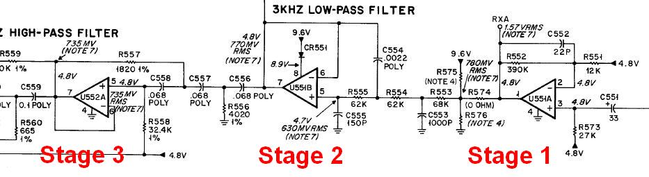
I measured the outputs of the receiver's audio amplifiers and filters, which use three dual op-amps. I numbered these stages 1 through 6 starting at the right where the "Detected Audio" signal enters the logic board on pin 3 of the connector that comes from the RF board on the other side of the radio. You can enlarge each of the schematic snippets below by clicking on them.
I begin with the MaxTrac's audio stages 1 through 3.
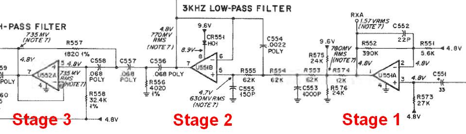
Here is the same circuitry from the Radius manual.
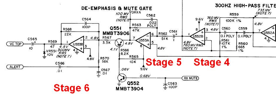
Now here's the rest of the MaxTrac's audio stages 4 through 6.
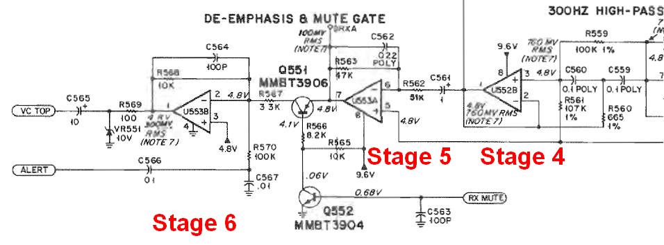
And finally the rest of the Radius audio stages 4 through 6.
I used the same input signal as above: 1,000 Hz tone at 3 kHz deviation. The important number is the one at the output of stage 6, as that feeds the volume control and the headset audio pin on the MIC jack. Here are the outputs of each stage along with what the schematic says they should be. All values are in millivolts AC.
| Stage | IC & Pin | Low | High | Sch |
|---|---|---|---|---|
| 1 | U551-1 | 1556 | 820 | 780 |
| 2 | U551-7 | 742 | 795 | 770 |
| 3 | U552-7 | 702 | 762 | 735 |
| 4 | U552-1 | 727 | 788 | 735 |
| 5 | U551-7 | 101 | 110 | 100 |
| 6 | U551-1 | 304 | 743 | 300 |
OK, so I see a big difference in the output of stage 1, however stages 2 through 5 are all nearly identical and match the values on the schematic. The output from stage 6 on the "low" radio matched what the schematic said it should be but this value was quite a bit lower than all the other radios I tested. I looked at the schematic and a quick calculation told me that stage 6 should have a gain of about 7-8, and that's what the "high" radio was giving me, so I think the schematic's value of 300 mV at the output of stage 6 is wrong.
Getting Down to the Component Level:
So I went to the next step: I pulled each logic board and, armed with the color X-ray view of the bottom of the board, I measured the resistor values around stages 1 and 6. Here's what I found:
| Stage | R# | Low | High | Sch |
|---|---|---|---|---|
| 1 | 551 | 5.6k | 12k | 12k |
| 1 | 552 | 370k | 388k | 390k |
| 1 | 553 | 62k | 68k | 68k |
| 1 | 573 | 27k | 27k | 27k |
| 1 | 574 | 12k | 0 | 0 |
| 1 | 575 | 12k | N.I. | N.I. |
| 1 | 576 | 12k | N.I. | N.I. |
| 6 | 567 | 3.3k | 3.3k | 3.3k |
| 6 | 568 | 10k | 22k | 22k |
| 6 | 569 | 100 | 48 | 47 |
| 6 | 570 | 100k | 56k | 56k |
Analysis and Conclusions:
I noticed several interesting things here. First, the "low" radio has a bunch of 12k resistors installed in stage 1 that the schematic says should either be zero or not installed. But the big difference is in the value of R568, a feedback resistor that controls the gain of stage 6. As Jamie on Mythbusters would say, "Well, there's your problem!" With a 10k resistor, the calculated gain of stage 6 would be about 3; with a 22k resistor, it would be 7-8. The gain of this stage on the "low" radio is less than half of the gain on the "high" radio and the voltage measurements show that to be true. The Radius Detailed Service manual has only one logic board - 5173 - whose parts values seem to match those in my 5172 board.
Motorola must have revised the parts values on the 5172 logic boards at one time. All of the schematics in the MaxTrac Detailed Service Manual have these same parts values.
Credits and Acknowledgements:
The MaxTrac schematics came from the Detailed Service Manual 6880102W84-O.
The Radius schematics came from the Detailed Service Manual 6880101W58-A.
Contact Information:
The author can be contacted at: his-callsign [ at ] comcast [ dot ] net.
Back to the top of the page
Up one level (MaxTrac index)
Up two levels (Motorola index)
Back to Home
This page created on Thursday 18-Jun-2015.
Article text, artistic layout, and hand-coded HTML © Copyright 2012 by Robert W. Meister WA1MIK.
This web page, this web site, the information presented in and on its pages and in these modifications and conversions is © Copyrighted 1995 and (date of last update) by Kevin Custer W3KKC and multiple originating authors. All Rights Reserved, including that of paper and web publication elsewhere.