Motorola index
Back to Home
as a CW Beacon Transmitter
By Robert W. Meister WA1MIK

|
MaxTrac index Motorola index Back to Home |
Using a MaxTrac, Radius, or GM300 as a CW Beacon Transmitter By Robert W. Meister WA1MIK |
|
Background:
Brian NB9E sent this article suggestion to me:
Could you or someone at Repeater-builder write a detailed article on the conversion and use of MaxTracs as CW beacons including pictures and connection points for attaching beacon controllers such as the ID-8 etc. It seems since these are abundant on eBay one could use these on 6, 2, 432, and 902 successfully as propagation beacons and relatively cheaply at that!
Further communication revealed that he wanted the radios to send CW that could be detected by any receiver. He didn't want to just send audio tones (Modulated CW) into an FM transmitter.
What We Need To Do:
Initially I gave him several reasons why this seemed to be rather difficult. The mobile radios needed to be put into transmit mode, wait some number of milliseconds for the synthesizer to stabilize, then find a way to key the RF on and off through a digital CW signal. I determined that the ID-8 would not work in this application because its one PTT output line could either be configured to send CW, or be used as a real PTT line. This project needed two distinct signals: a PTT output to put the radio into transmit mode, and a digital CW line to key the RF on and off.
After giving it more thought, it got my curiosity and I looked for another solution. I found it in the ID-O-Matic IV product, available for $39 as a kit from www.hamgadgets.com. This inexpensive repeater identifier and timer module has a PTT output line AND a digital CW output line, just what the doctor ordered. These signals have been available since the ID-O-Matic first came out several years ago. It has been designed to support beacon use too. The board can do a lot more, but this is all we need from it. From this point on, I'll refer to the ID-O-Matic as the "IOM".
A little experimenting with an 800 MHz MaxTrac proved that CW keying of the RF output IS possible and it's actually a lot easier than I first thought. The point I located to key the transmitter on and off requires about 50mA of current to ground to disable the transmitter. This is well within the allowable specifications for the ID-O-Matic's CW output.
This solution should work for all bands of the following Motorola mobile radio series: MaxTrac, Radius, GM300, and even the MaraTrac. However, not all radios will work in the amateur bands without some adjustments or modifications. All of these have essentially the same logic board schematic and circuit. A few wires and parts will be installed in the radio and the IOM will need to be connected to the radio's modular MIC jack. Mounting and/or enclosing the IOM is "...left as an exercise for the student." There are enclosures for sale on a popular auction site, or you can use some double-sided foam tape and stick the IOM right to the plastic cover of the radio.
Design Goals:
The radio should operate normally in all respects when the IOM is not connected to it. This means it has to pass normal voice audio when a microphone is plugged in. The modifications should be easily made and removed if necessary, and without removal of the circuit boards or cutting of traces.
I want to use off-the-shelf products that are easily constructed and set up, with minimal additional parts, modifications, and monetary expenditure.
Modifications to the Radio:
You may have to alter the programming software or the radio to make it transmit on the frequency you want. Make sure the radio is properly programmed and aligned and working on the desired frequency before you do any modifications. You probably want to set the radio for just one mode or channel, so it always powers up on the correct frequency in case the power fails.
You'll need the following items:
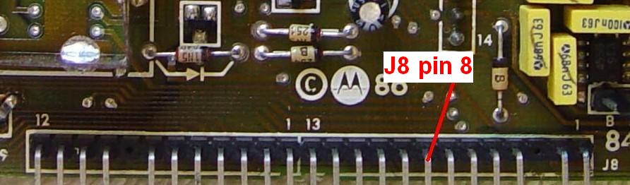
The IOM will make all of its connections entirely through the front panel (or, in the MaraTrac, internal) modular MIC jack. The Ground and PTT signals are already present there but the IOM needs two additional signals: 6-20VDC for power, and a line to carry the digital CW signal to key the radio. The MaraTrac radio already provides 13.8VDC power on pin 1 of its MIC jack, so we'll use the same pin on the other radios by making that connection with a 10-ohm current-limiting resistor, which will act as a fuse if too much current passes through it. That leaves pin 2, the only remaining unused/spare pin, to carry the digital CW signal back into the radio. On VHF, UHF, and 800 MHz MaxTrac, Radius, and GM300 radios, both pin 1 and pin 2 on the MIC jack are spare and make their way back to the logic board. The 900 MHz MaxTrac's MIC jack doesn't utilize those pins either, but their respective pins on the logic board are used for other purposes. A 12-conductor cable carries the signals between the logic board and the VOL/MIC board in the control head. Here's a photo showing J8 on the front edge of the logic board with pin 8 identified.
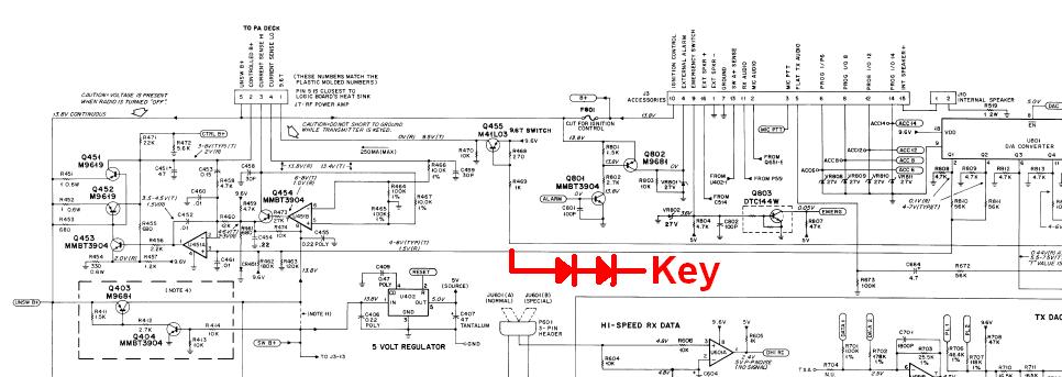
The radio's power control circuit will be shunted to ground through two small-signal silicon diodes, such as 1N914 or 1N4148, to disable the transmission of RF energy. This means the IOM's CW ID output has to be configured for active-HIGH. When the "Key" point is grounded, no RF will come out of the radio. Some wire and two diodes have to be added to carry this signal from the MIC jack, through the cables to J8 on the front of the logic board, to the power control line that terminates at U451 pin 3 on the logic board. The location of this small 8-pin IC will vary depending on what logic board is in the radio, however in general it's in the right rear quarter, near the 5-pin cable that goes to the power amplifier at the back of the radio. Consult the appropriate service manual to find where it is; they're all posted on repeater-builder. All of the logic boards in the MaxTrac-based radios use the same component values and numbers in this area. The schematic segment below shows the point that has to go to the IOM's CW ID output.
An alternative connection point is the junction of the two 56K resistors R810 and R811 coming from U801, the digital-to-analog converter IC, that feeds U451 pin 3. My article about MaxTrac Manual Power Control has some information about finding this spot and a similar MaraTrac Manual Power Control article covers that board. No circuit board cuts are necessary; just attach the diodes to the resistors, circuit board trace, or U451 pin 3, whichever is easiest to get to.
The reason for the two diodes is that directly grounding U451 pin 3 causes the output of that op-amp to go to full positive, causing maximum RF output to be generated. The two diodes prevent pin 3 from going all the way to ground, but are sufficient to pull the pin low enough to shut off the RF power amplifier.
Remember that the keying signal we're bringing out to the MIC jack will shut off the transmitter when it's brought to ground, which is the opposite of a normal CW keying circuit. That's why we need to set the IOM's CW output to active-HIGH.
Wiring the MaraTrac:
Power is already present on the MIC jack pin 1, unlike the other radios. The MaraTrac's MIC jack pin 2 goes no where, so you'll need to add a wire from that pin, on the interconnection board at the front of the radio, through two series-connected diodes to U451 pin 3 on the logic board. You will have to leave the top cover off the MaraTrac, or get creative and drill a hole to pass the cable through. While I doubt anyone would use a MaraTrac as a beacon transmitter, you never know who will want to. Also, beacon transmitters are limited to 100 watts transmitter output power.
Wiring 900 MHz MaxTracs:
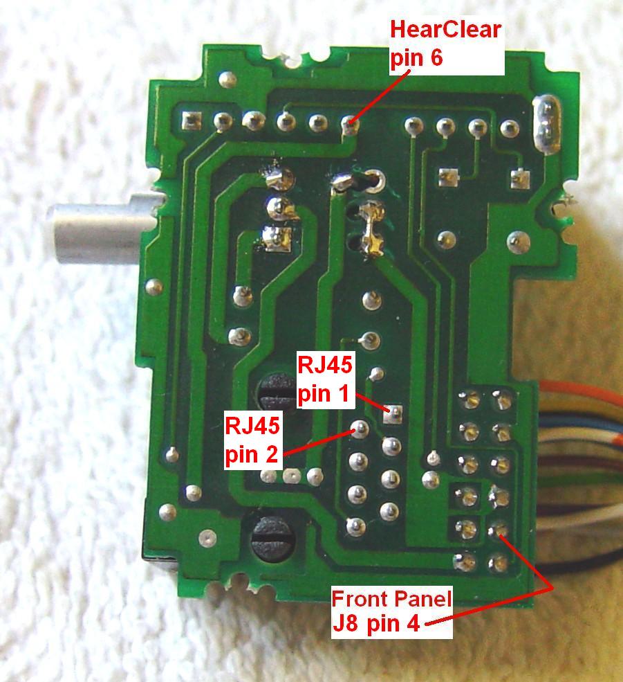
The MIC jack pins 1 and 2 are not connected to anything. You will need to remove the VOL/MIC board from the control head and make two connections there. Connect the 10-ohm resistor from pin 1 of the MIC jack to pin 6 of the vertical HearClear module at the end of the board to pick up +9.6VDC for power. Wire the MIC jack pin 2 to the unused solder pad that has a wire installed in it going to J8 pin 4 on the logic board. If there is no wire there you'll have to add your own. Add a wire from J8 pin 4 through two series-connected diodes to U451 pin 3, both on the logic board. The photo below shows the back of the 900 MHz VOL/MIC board.
Wiring All But 900 MHz MaxTrac:
The MIC jack pins 1 and 2 are wired back to the logic board at J8 pins 8 and 9 respectively. Connect the 10-ohm resistor from J8 pin 8 (Spare 1/Pin 1) to J8 pin 5 (Switched B+), both on the logic board. Add a wire from J8 pin 9 (Spare 2/Pin 2) through two series-connected diodes to U451 pin 3, both on the logic board.
Building the Interface Cable:
You'll need the following items:
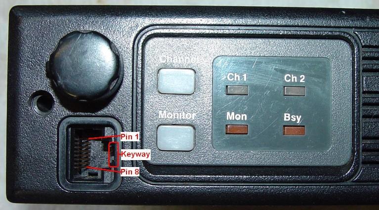
On the 8-pin modular MIC jack, with the tab cutout to the right and the pins to the left, pin 1 is the uppermost pin. The MaxTrac, Radius, and GM300 all have their MIC jacks oriented this way. When you make your interface cable (or chop an old network cable), verify the wiring. Here's a photo of the front of a radio showing the pin orientation.
The IOM uses a terminal block that could have 10 (IOM II) or 12 (IOM III and IV) connection points. Luckily the signals we need are on the same points in all varieties. Make your cable according to the table below. The signal names in parentheses detail the uses those pins will have.
| IOM Pin # and Signal Name | MIC Jack Pin # and Signal Name |
|---|---|
| 1 - Ground | 4 - Ground |
| 2 - 6-20VDC | 1 - Spare 1 (Switched B+) |
| 3 - PTT Output (Active-LOW) | 6 - PTT Input |
| 4 - CW Output (Active-HIGH) | 2 - Spare 2 (CW Input) |
Use stranded wire if possible to connect to the IOM, or if you use an old network cable, the thinner the better. The terminal block's screws are quite small and will probably grip stranded or thin wire much better.
Configuring the IOM:
The older IOM II used jumpers for some items and a serial port for others. They switched entirely to serial communications with the IOM III and then to a USB interface with the IOM IV. You'll need to download and install a driver file on your computer to configure the unit. I used the HyperTerm program on my WinXP laptop. Follow the well-written instructions provided with the IOM. I ended up printing the entire PDF file.
If you're reusing an existing IOM, it might be wise to reset the configuration to the factory default before setting the beacon parameters. I believe this is an option on the "C" (Configuration) screen, but isn't shown in the manual.
I constructed an IOM from scratch so there was no previous configuration to read from the device. I just connected it to my computer through a USB cable and started programming the parameters I wanted. The ones listed below in parentheses are optional. The information in the "What to type" column are the command characters I typed to get to that field, along with any data required for that field. I used a semicolon to separate the command characters. Terminate everything by pressing the <ENTER> key.
| IOM Parameter | What to type | Notes |
|---|---|---|
| Beacon interval | 1; 5; 60 | yours should be longer |
| Beacon message | 2; 2; de wa1mik | use your own call sign |
| (Morse ID speed) | (2; 5; 1-20) | (pick your speed up to 20) |
| (PTT polarity) | 4; 3; 0 | active-low - MANDATORY |
| CW polarity | 4; 6; 1 | active-high - MANDATORY |
Remember to save the modified configuration by writing it back to the IOM's FLASH memory with the "W" command when you're done.
Testing:
Before I had an IOM, I connected a function generator to the CW Keying input of a low-band (6 meter) radio. It was set at 8Vp-p with a +4V offset, so the signal at the input to the radio went from 0V to 8V. The diodes only let this signal through when it was less than about 5V. The function generator was set to output a 50% duty cycle square wave at 100 Hz. Each cycle takes 10 milliseconds, so it's on for 5 milliseconds and off for 5 milliseconds.
I connected the function generator output to one input of a dual-trace oscilloscope; this is shown below in the upper/red trace. I connected the radio's RF output through suitable attenuators to the other input of the scope; this is shown below in the lower/blue trace. I then grounded the radio's PTT line to cause it to transmit. Initially I started at a very low rate (under 1 Hz) then ramped it up to 100 Hz for the snapshot below.
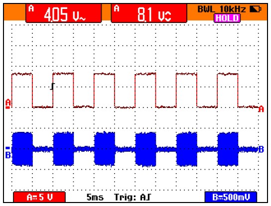
The rise time - the time from the rising edge of the input keying signal until full RF output - is approximately 150 microseconds. I suspect the fall time is similar but I didn't measure it. The waveform was a textbook CW signal. I ran the function generator up to over 3,000 Hz and the RF output followed it precisely, although at that speed the waveform started having somewhat rounded corners. It will do fine at any FCC-legal CW ID speed.
You will hear a continuous signal in a nearby receiver whenever the PTT line is activated. The synthesizer and TX exciter are still quite active and putting out several milliwatts. The only thing being keyed is the power amplifier, which feeds the antenna.
I wired the IOM to a 40w UHF MaxTrac sitting open on the bench using the four signals exactly as the article describes, however I skipped the MIC jack and used clip leads directly to the diodes and J8 contacts. It worked perfectly. Every 60 seconds it keyed the radio, waited about half a second, sent the CW ID message, waited about a second, and unkeyed the radio. I listened to the beacon transmission in LSB, USB, and CW modes. There is some chirp in the CW signal as received on an Icom IC-R10 communications receiver, but as none of these radios are designed for frequency stability, this is not a big deal. It adds a nice characteristic to the beacon signal.
You may not be able to program the radio to every possible beacon frequency. The best you can do is get within 5, 6.25, or 12.5 kHz, depending on the band. Get it as close as you can, then adjust the reference oscillator (WARP) coil to get the radio on the exact frequency you want.
Acknowledgements and Credits:
ID-O-Matic and HamGadgets were owned by Dale Botkin NØXAS but he has since sold the web site and products to RadioDan. Information about the IOM came from his web site and excellent product documentation.
Thanks go to Kevin W3KKC for supplying an ID-O-Matic IV kit specifically for this article.
The various radio model names are trademarks of Motorola, Inc.
All photos were taken by the author.
Contact Information:
The author can be contacted at: his-callsign [ at ] comcast [ dot ] net.
Back to the top of the page
Up one level (MaxTrac index)
Up two levels (Motorola index)
Back to Home
This article was conceived on Sunday 21-Sep-2014.
Article text, photos, artistic layout, and hand-coded HTML © Copyright 2014 by Robert W. Meister WA1MIK.
This web page, this web site, the information presented in and on its pages and in these modifications and conversions is © Copyrighted 1995 and (date of last update) by Kevin Custer W3KKC and multiple originating authors. All Rights Reserved, including that of paper and web publication elsewhere.