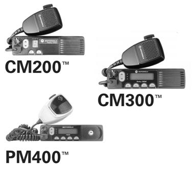
If anyone can provide a replacement photo of all three radios please drop an email to the page maintainer.
|
Up one page (Motorola index) Back to Home |
The Motorola "Commercial Series" Index Page (CM140, CM160, CM200, CM300, CM340, CM360, and PM400 mobiles, CP150, CP200, CP200 XLS and PR400 handhelds) Originally Compiled by Robert Meister WA1MIK (SK) from information provided by Mike Morris WA6ILQ and others. Currently Maintained and Updated by Mike Morris WA6ILQ |
Contributions, comments / critiques / suggestions / corrections / updates for this page (or any page) are welcome and appreciated.
Actually that applies to any page at this web site! (even one that just points out a typo).
If anyone can provide a replacement photo of all three radios please drop an email to the page maintainer.
NOTE: If you are here looking for a Motorola-labeled rack-mount aircraft base radio (Sample Photo, opens in a new browser tab) please understand that there was an undesirable duplication of model numbers between the the Land Mobile Radio Division and "Space and Systems Technology Group" of Motorola. The Land Mobile Radio "Commercial Series" (CM200 / CM300 / PM400) are covered on this page.
The rack-mount CM-series of Air Traffic Control (ATC) and Air Traffic Information Service (ATIS) radios (aviation base station radio equipment) were actually made by General Dynamics and branded as Motorola.
They had model numbers of CM-50, CM51, CM-200, CM300, CM350, CM-400 or CM-450.
Example Photos: TX Photo 1 TX Photo 2 TX Photo 3 TX Photo 4 TX Photo 5 TX Photo 6 TX Photo 7 TX Photo 8 RX Photo (each of the above eight links open in a new browser tab)
These avionics base radios have been seen with frequency labels ranging from from 118 MHz to 280 MHz.
They are AM modulation and not practical for amateur radio 220 MHz use except maybe for the receiver preselectors, and most of those were for the 118-130 MHz range.
Also these radios are no longer supported - see this General Dynamics Service Repair Cancellation Notice.
There are a few more comments on these radios in the CM Series Notes article below.
The Motorola "Commercial Series" were the follow-on series to the
"Professional Series" (the CDM mobile and HT750/1250/1550 handheld
product line, also called the "Waris" series). And no matter what you
read on the web (especially eBay) the CMs are NOT P25 or any form of digital.
There is a model number decoder below.
The CM mobile series was discontinued in November 2014; they were replaced by the
CM200D / CM300D / PR400D (suposedly the same radio, just does both
conventional and DMR) or the XPR series of mobile radios (conventional and DMR).
Well, they are not the same radio, they are very different inside.
All support of the non-D-series CM radios has been discontinued. Parts are limited.
The CM200 / CM300 / PM400 are the most common mobile members of
the Commercial Series in the USA and were made in three power levels (1-25 (VHF & UHF), 25-45 (VHF),
and 25-40 (UHF) watts. VHF radios were made in two ranges, 136-152 MHz (rare) and
146-174 MHz (common). The UHF version radios were made in two ranges, 438-470 MHz
(common) and 465-495 MHz (rare). In other regions you find the CM140, CM160, CM340 and CM360.
Note that the mobile radios from this series have a MUCH smaller heat sink that the previous CDM or
GM radios and hence are a MUCH lower duty cycle radio. One piece of literature says the CMs are 5%
duty cycle.
Programming the "Commercial Series" Radios:
Mobiles:
The bad news is that the first thing you will discover is that your existing RJ45-ended mobile programming cable
will NOT be able to program the Commercial Series mobile radios, you will get a
3-line error message reading:
Error # 512...or something similar.
Unable to read
Check to see if radio is connected.
The good news is that you can modify your existing programming cable by adding a
100 ohm resistor between two of the pins of the of the RJ-45 plug.
The cable that is modified with the resistor is completely backward compatible and can be used
with all of the previous radios.
See the "Updating the Cable" article below.
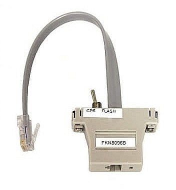
Or you can build your own version of the FKN8096 with a RJ-45 jack, a toggle switch, a resistor
and a RJ-45 cable, or even the stub of an ethernet cable.
You can also program the radio through the accessory connector on the rear of the mobile radio.
Handhelds:
The CP150, CP200 and PR400 and similar handhelds is programmed with
the PMDN4077AR
Programming Cable, which is a USB-A to a 3.5mm (1/8 inch) TRS plug (3-contact,
tip, ring, shank). (link opens in a new browser tab).
On the other hand, the CP200D and similar "D" handhelds program with MotoTRBO R16.0 Build 823 software and a Motorola PMKN4128A cable which strictly from the radio progamming point of view, is nothing more than a simple USB-A to USB "micro-B" cable. If all you want to do is program your "D" handheld, use the cellphone cable you probably already have and save your money.
The PMKN4128A handheld cable is specified for the CP100D, CP200D, SL1, SL300, SL1600, SL2600, SL3500e, SL4000, SL4000e, SL4010, SL4010e, SL7550, SL7550e, SL7580, SL7580e, SL7590, SL7590e and the R2 handhelds.
The actual Motorola PMKN4128A cable is that USB-A to USB"micro"-B cable plus a chunky ferrite core near the USB-A end and an additional BNC pigtail for audio testing. (link opens in a new browser tab). If you need one it's a readily available cable, even Amazon has it.
Both:
The non-"D" version commercial series mobiles and handhelds are programmed
with RVN4191 CPS, which runs under Windows 95, 98, XP, 7 and both 32‑bit and
64‑bit Windows 10.
The help files for the RVN4191 CPS mention the CP150, CP200 and PR400 handhelds,
the CM200, CM300, PM400 mobiles, the EP450, EM200, EM400, GM3188, GM3688,
GM3189 and GM3689, and probably more. Revision R05.16 is the one to look for and
use as it is the last one that allows wide and narrow selection and does it on a per-channel
basis. The later versions R05.17 and R05.18 strictly enforce 12.5 kHz narrowband unless
an active wideband entitlement key (also called a license entitlement) is present.
Your author has been told (but has been unable to verify) that:Translation: Once you program the radio with any of the narrowband only CPS Revisions / Versions then you can't go back to a wideband / narrowband version. This locks you into narrowband unless you have a entitlement key.
1) The wideband entitlement keys are no longer available.
2) Once you use a later version you can't go back to an earlier version.
Once you have the programming cable and the software you download a codeplug and then you CAN hex edit a saved codeplug file and stretch the frequency boundaries of a CM / PM / CP / PR series... for example a 146-174 MHz radio can be stretched down to 144 MHz amateur radio frequencies. Or a 438-470 MHz radio stretched up to 476 MHz, or the receive side of a 465-495 MHz radio down to 462 MHz for GMRS. Tricking any individual radio to operate out of it's design range depends on the tolerances of the individual receive and transmit RF components... you might loose a little sensitivity and transmit RF power... Most will work, a few might not. See the detailed article below.
Commercial Series Manuals, Brochures, Guides, and Other Printed Material:

|
Commercial Series Mobiles Product Line Model Number
Decoder 10KB PDF This was extracted from the Basic and Detailed service manuals listed below and compiled by WA6ILQ. |
|
|
A CP140 / CP160 / CP180 Brochure (handhelds) (2006 vintage) 2.85 MB PDF |
|
|
A CM200 / CM300 Brochure (2004 vintage) 2.85 MB PDF |
|
|
CM300 Specification Sheet (2010 vintage) 141KB PDF |
|
|
CM200 / CM300 / PM400 Mobile Radio Basic Service Manual 6802966C15-A (2004) 3.9 MB PDF |
|
|
CM200 / CM300 / PM400 Mobile Radio Detailed Service Manual (VHF) 6802966C20-C (2009) 10.1 MB PDF |
|
|
CM200 / CM300 / PM400 Mobile Radio Detailed Service Manual (UHF) 6881098C00-A (2007) 9.1 MB PDF |
|
|
CM200d / CM300d
Mobile Radio Basic Service Manual 68009618001-A (June 2013) 16 MB PDF This manual is for the "D" series / MotoTurbo radios. |
|
|
CM200 / CM300 / PM400
Mobile Radio Installation Guide 68P02966C25-A (2003) 880 kB PDF Chapters 7 through 10 cover local noise reduction in mobile radios. Worth reading. |
|
|
CM200 User Guide 6802966C30-B (2004) 975 kB PDF |
|
|
CM300 User Guide 6881096C22-A (2004) 2.0 MB PDF |
|
|
PM400 User Guide 6881096C32-B (2004) 2.9 MB PDF |
|
|
The Motorola Cancellation
Memo on the CP200, PR400, CM200, CM300 and PM400 series 2.9 MB PDF Dated 08-22-2014, Suggested replacements include the CP200d handheld, the CM200d, CM300d and the XPR series mobiles. |
Modification Articles and Other Information:
|
|
Updating the standard Motorola mobile programming
cable so it works with the "Commercial Series" radios by Robert W. Meister WA1MIK (SK) Motorola wants you to purchase an FKN8096B Flash Adapter to adapt your standard RIB-to-8-pin-radio-cable to put the mobile radio into programming mode. You can easily modify / upgrade your existing programming cable with a 100 ohm 1/4 watt resistor. This article walks you through the how and the why. The cable that is modified with the added resistor is completely backward compatible with all of the older radios. |
|
|
Stretching the Frequency Range of the Motorola "Commercial Series" Radios by Mike Morris WA6ILQ This article walks you through the process to hexedit a codeplug (NOT the CPS) to allow operation out of band. Your individual success depends on how far out of range you go... Back in January of 2020 the author needed to stretch a 146-174 MHz CM300 down to 144 MHz (read the article for the details). The same method will allow you to stretch the receive side of a 465-495 MHz radio down to 462 MHz for GMRS. And you could have a 438-470 MHz radio accept a frequency at, for example, 436 MHz or 474 MHz. Emailed reports confirm this process has been succcessful on CM200 and PM400 mobiles and a CP200 handheld... the other "Commercial Series" Radios should be similar. The actual performance of an out-of-range receiver and transmitter is limited by the RF components in the indvidual radio. |

|
The accessory connector on the Commercial Series mobile radios is 16 pins, and is programmed
similar to the GM300 product line. It has several programmable digital inputs / output pins, and
each can be set to one of several different behaviors. Internally each output pin is buffered with a transistor
with the collector pulled up to 3.3V through a 3.3K resistor. Obviously these are meant to work with
3.3 volt logic circuits. The transistor they used is rated for an absolute maximum collector current
of 100mA and I'd limit it to 50, maybe 75mA. They are difficult to replace unless you are an expert at
repairing a surface-mount board (and have the replacement parts!) In other words, you CAN NOT drive relays directly with the programmable pins. Pin 4 is different and pulls up instead of down, and can drive the coil of a small relay (max current 100ma and don't forget the reverse biased diode). Motorola specifies a HLN9457AR or a HLN9457 16-Pin Accessory Connector Kit for the CM series and the M1225s, however there are more reasonably priced sources. Connector / interfacing / cable kits can be purchased from ebay seller "mre1032", Kurt Meltzer, KC4NX / WB9KNX / Meltzer Radio Engineering. (off-site pointer, opens in a new browser tab) The last time I looked there were over two dozen listings for 16-pin cables for a number of Motorola models that use the 16 pin connector. Full Disclosure: I have no relationship with Kurt other than as a very satisfied email-order customer and he's not paying me for this recommendation. I think Kurt's cable kits are wonderful and they have saved me a lot of frustration. He's been very receptive to customizing kits. I just have 70+ year old eyes and have big fat fingers that have difficulty crimping the accessory connector tiny pins onto the individual wires, and then getting the pins into the plastic body rightside up (needlenose pliers and a large illuminated magnifying glass are a big help). (off-site pointer, opens in a new browser tab) |
|
|
The CM200 / CM300 / PR400 Mobile 16-pin
Accessory Connector 16 kB PDF This is a one-page cheat sheet - it's just a PDF of the one page from the Basic Service Manual. Tip: the odd pins are on the heat sink side, the even pins on the other side.  Photo by David Harrelson, KK4YPR. Click for a larger image. |
|
|
The front panel microphone jack is a normal 8-pin, not the 10-pin of the CDM series. The Commercial Series mobiles ship with one of these microphones: HMN3596 Standard Microphone, HMN1035 Heavy Duty Microphone, RMN5029 Enhanced DTMF Keypad Microphone, or the RMN5018 Mag One Microphone (Low Cost, 6 months warranty only). The DTMF microphones made for the prior models (Maxtrac, Radius or CDM) will not work with the CM / PR mobiles. The RMN5029 does not have a DTMF tone chip inside the microphone case, instead the keypad sends data to the radio and the radio circuitry generates the tones. |
|
|
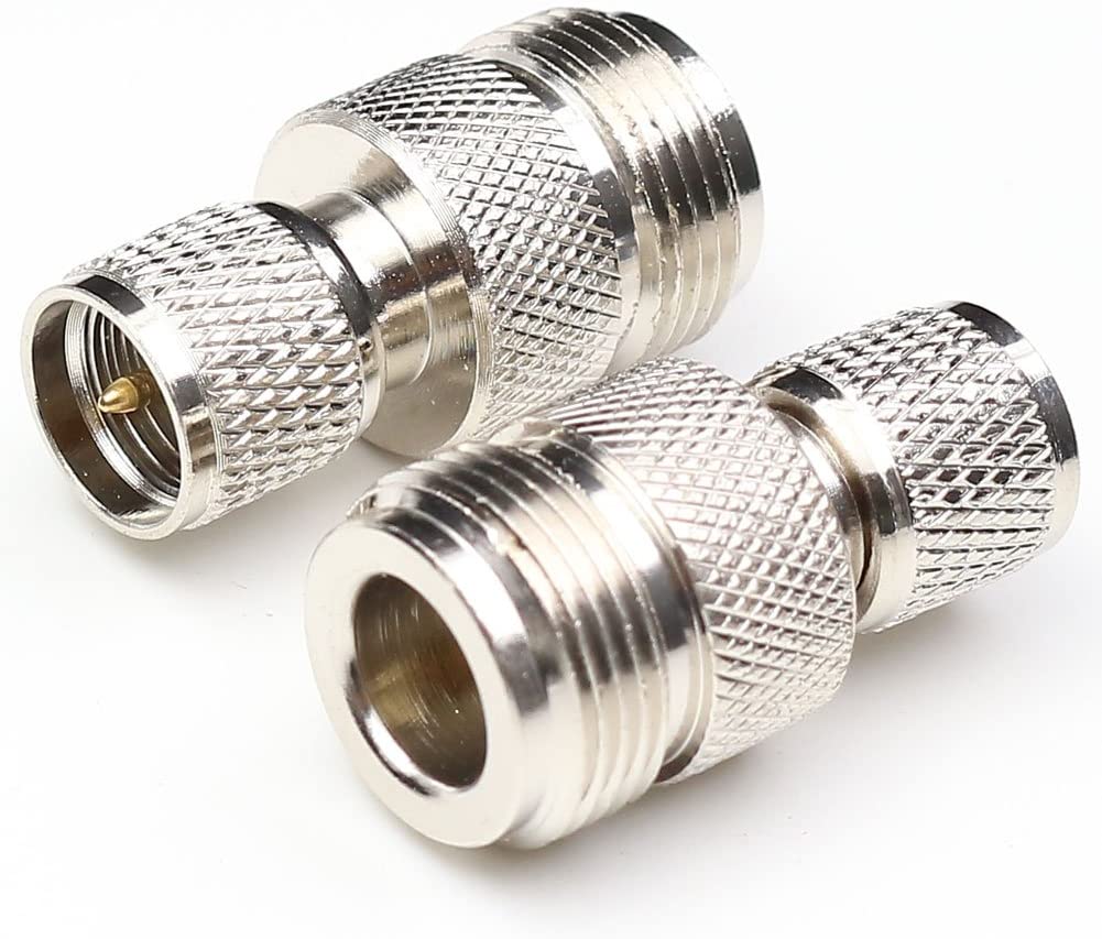
Like the Maxtrac, Radius LRA, GM300 and CDM series the antenna connector is a Mini UHF female and very easy to break if you use a common adapter and use stiff coax like LMR400 or RG213. Your author considers a pigtail (mini UHF male to UHF or N female) to be a requirement for the bench or base operation. The pigtail relieves the stress on the radio connector. The problem got so bad that Motorola came up with the 8 inch long HKN9557A Mini-UHF male to UHF SO239 female Antenna Adapter (for about $30-$50 depending on source), and an 8 foot version as the HKN9088A Mini-UHF male to UHF PL259 male Adapter Cable (about $40-$55). You can make your own for a lot less money... and you will have the option of a different connector. I made up a few mini-UHF-male to N-female cables with RG-400 cable for my test bench and for sites back when I got started with Maxtracs. A friend prefers mini-UHF-male to BNC female for his bench, and I'm switching over as I make new ones. It's your choice when you make your own. |
|
|
Samlex offers a SEC-1212-SM (12 amp) and SEC-1223-SM (20 amp) power supply and tabletop cabinet that fits the CM200, CM300, CM200D, CM300D, PM400 and also the SM50, SM120, M1225, GTX, XPR2500, DM1600 units. |
|
|
Three Service Notes: If your wattmeter says you have a low RF power situation on a new-to-you radio...
|
Accessories and Parts:
Contact Information:
The author, Mike Morris WA6ILQ, can be contacted via the page maintainer link at the top of the page.
Back to the top of the page
Motorola index
Back to Home
A joint CDM / CM page was created 07-Oct-2016 by WA1MIK from material on the main
Motorola page originally written by WA6ILQ.
That page was split and the CM material was moved to this new page in October of 2021
This web page, this web site, the information presented in and on its pages and in these modifications and conversions is © Copyrighted 1995 and (date of last update) by Kevin Custer W3KKC and multiple originating authors. All Rights Reserved, including that of paper and web publication elsewhere.