Motorola index
Back to Home
Originally by Robert Meister WA1MIK (SK)
Updated by Mike Morris WA6ILQ February 2022

|
Commercial Series index Motorola index Back to Home |
Making a Programming Cable That Works With a "Commercial Series" mobile radio (CM200, CM300, PM400 and similar) Originally by Robert Meister WA1MIK (SK) Updated by Mike Morris WA6ILQ February 2022 |
|
Problem:
You acquired a CM200, CM300, PR400 (or some other member of the Commercial Series) mobile radio and want to program it. You notice there's a standard modular microphone jack on the front of the radio, so you fire up the appropriate CPS, plug in your standard trusty RIB and modular programming cable, and the radio does not respond. No radio-to-computer communications at all.
Some quick research verifies that the same two pins are used for programming: Serial Communications Input (SCI) and Ground (some books call the pin the Serial Communications Interface). You've used that cable to successfully program MaxTracs, GM300s, GTXs, and many other modular jack-equipped radios before, so why won't this one work?
Well a bit more research might lead you to the "Commercial Series" Detailed Service Manual, which states:
The HOOK line (J802-6) is used to inform the µP which type of microphone or SCI lead is connected to the microphone socket. The voltage of the HOOK line is monitored by the µP (port PE0, MIC_SENSE) through a resistor divider on the main board. When the HOOK line is grounded (on hook condition) or floating (2.8V nominal), the µP sets the mux (U803) for keypad operation to allow the use of microphones with a keypad (DTMF and programmable buttons). When the HOOK line is connected to +9.3v DC, the µP sets the mux for SCI (programming) operation and firmware loading. This mode is also used to select low cost mic operation where the gain of the microphone path is increased (on the main board) to compensate for not having a pre-amp in the low cost mic.
So it seems all you need to do is connect the HOOK line to a source of +9.3vDC,
but where can you get that from?
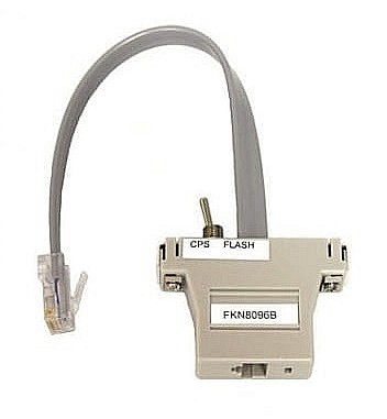
Motorola wants to sell you an FKN8096A / FKN8096B / FKN8096C
programming adapter (photo) which has a
switch between pins 1 and 3. But there's an easier way.
Solution:
It turns out that the front panel MIC jack has assigned signals to the previously spare / ununsed pins found on older radio series (Maxtrac, GM300, etc.) microphone jacks, including a convenient source of +9.3vDC, just what you need. Here are the signals on the various pins.
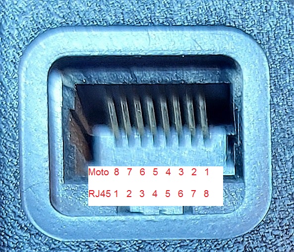
NOTE: The Commercial Series manuals use RJ45-style pin numbering, which is reverse from past Motorola pin numbering. The reason is historical: the first 8-pin radio was the Maxtrac and the microphone connector was positioned on it's side, with the locking tab on the right. The Motorola Maxtrac designers designated the top-most pin as pin 1. When you look at the front of a CDM or Commercial Series radio the microphone connector notch (for the locking clip) is on the bottom. The numbers that the Maxtrac designers used are unfortunately reversed from the RJ45 numbers. (photo)
| Microphone Jack Pin Number | Signal Name | Comment | |
|---|---|---|---|
| (RJ-45 Pin # and new Moto Pin #) | (Old Moto Pin #) | ||
| 1 | 8 | Handset Audio | RX Audio, de-emphasized, squelch muted. |
| 2 | 7 | SCI / Row | The function of this pin depends on the voltage applied to the Hook pin. When configured as "DTMF Keypad Row" this pin will receive DC voltages generated by the rows of the DTMF microphone. When configured as SCI then serial communication is enabled (programming or flashing firmware). (SCI is referred to as BUSS+ in several of the other Moto product lines). |
| 3 | 6 | PTT | This pin is active low and has a 10 K pull-up resistor to 9.3 volts. The microphone PTT button grounds this pin and a diode pulls pin 3 (External PTT) of the accessory connector low to inform any accessory of the transmit state. |
| 4 | 5 | Microphone Audio High | Input impedance is 500 ohms. 80mv RMS at 1 KHz produces 60% deviation. This audio path is active only when the microphone is keyed. |
| 5 | 4 | Ground | |
| 6 | 3 | Hook | When the microphone is on hook this pin is grounded and pins 2 and 7 will be configured as "Column" and "Row". When the mic is off hook this pin will float to 2.7 volts and pins 2 and 7 will still be configured as "Column" and "Row". When 9.3vDC is applied to this pin then pins 2 and 7 will be configured as "Boot" and "SCI". |
| 7 | 2 | Boot / Column | The function of this pin depends on the voltage applied to the Hook pin. When the Hook pin is low (i.e. configured as "DTMF Keypad Column") this pin will receive DC voltages generated by the columns of the DTMF microphone. When the Hook pin has 9.3vDC on it then asserting this pin will put the µP into Boot state (for loading firmware). |
| 8 | 1 | +9.3 Volts DC | Regulated DC voltage, 50 milliamps maximum |
The stock modular RIB-to-radio programming cable uses only pins 2/7 (SCI) and 5/4 (GND) of the microphone connector. These connect to the RIB (DB25) pins 1 (ground) and 15 (SCI). There is a jumper inside the RIB plug from 4 to 11. So all you have to do is add a jumper to your existing modular programming cable, inside the 8-pin microphone plug connector or the hood of the DB25 end, such that it connects the wires going to the modular plug pin 8/1 to pin 6/3. These wires should otherwise be unused. You should use an ohmmeter to verify the proper pins and connector orientation.
The new and improved programming cable is now wired up thusly:
| RJ-45 Modular Pin |
Signal Name | RIB DB25 Pin |
Notes |
|---|---|---|---|
| 1 | RX Audio | None | |
| 2 | SCI | 15 | Stock programming cable |
| 3 | Mic. PTT | None | |
| 4 | Mic. Audio | None | |
| 5 | GND | 1 | Stock programming cable |
| 6 | Hook | None | Connect to pin 8 through 100 ohm resistor |
| 7 | Boot_Res | None | |
| 8 | +9.3V source | None | Connect to pin 6 through 100 ohm resistor |
Note: Jumper: inside the RIB DB25 pin 4 must still be connected to pin 11.
So jumpering Motorola pin 1 (RJ-45 pin 9) to Motorola pin 3 (RJ45 pin 6) is simple, and it now works great for the CM200, CM300, and PM400 radios, and probably a bunch of other commercial and professional radios made since the mid-1990s, and it will still work well with older radios.
Cautions With Other Radios:
MaxTrac, Radius, GM300, DeskTrac, SM50, SM120, M1225, R1225, CDM, and GTX radios either don't use pins 7 and 8 (what some of them refer to as pins 1 and 2), or supply only 5-12v or have a 27v Zener diode on the Hook line, so the added jumper will have no effect.
However, you WILL have a problem if you use this modified cable on a MaraTrac. This is because the MaraTrac has full battery voltage (13-14V) on that pin (they number it pin 1) at basically unlimited current (well, until something burns up) and the Hook input on the logic board has a 10V Zener diode protecting it, unlike the PTT input which has a 27V Zener diode protecting it. To prevent burning anything out, I recommend that you use a 100 ohm 1/4 watt resistor instead of plain wire for the jumper between pins 1/8 and 3/6 on the modular plug.
If you're using a so-called RIB-less programming cable instead of a RIB and the standard DB25-to-RJ45 modular programming cable, you still should be able to access the other end of the cable and add the resistor to the appropriate wires. (Hopefully the manufacturer used a cable with all eight wires present.) Use a DC voltmeter to determine which wire has +9.3vDC on it; that will be pin 1/8. You can then figure out which wire goes to pin 3/6 and add your resistor between those two wires.
Other Wiring Changes:
Optional if you are using a RIB: While you're inside the DB25 end of your programming cable, you can also connect a wire from the modular plug pin 4 (Mic. Audio) to your DB25 pin 12 (SWB+ power input) so the radio will supply power to the RIB in case the battery should run low during a programming session. The Mic. Audio line has about 8VDC imposed upon it to power the preamplifier built into most Motorola microphones, so it could help keep a RIB running too.
Contact Information:
The author can be contacted at: his-callsign [ at ] comcast [ dot ] net.
Back to the top of the page
Commercial Series index
Motorola index
Back to Home
This page originally posted on Tuesday 16-Jul-2013.
This web page, this web site, the information presented in and on its pages and in these modifications and conversions is © Copyrighted 1995 and (date of last update) by Kevin Custer W3KKC and multiple originating authors. All Rights Reserved, including that of paper and web publication elsewhere.