Up two levels (Moto Index)
Back to Home
Trials and Tribulations with Transmitter PL
By Lou Harris N1UEC
Edited and HTML'd for www.repeater-builder.com
by Mike Morris WA6ILQ
with additional input from Bob WA1MIK

|
Up one level (MSF5000 index) Up two levels (Moto Index) Back to Home |
Yet Another Journey through the MSF5000 Trials and Tribulations with Transmitter PL By Lou Harris N1UEC Edited and HTML'd for www.repeater-builder.com by Mike Morris WA6ILQ with additional input from Bob WA1MIK |
|
Some important notes from the editors:
Seems that many folks that are repurposing the New Jersey 900 MHz MSF5000s are struggling with making the output PL follow the user input, so that a simple, external, offsite IRLP or link setup can be utilized. I fell into the same boat, but, as I am a Batwing purist, I would like to not have to hack up the station just to get this to work.
I've read some of the stories about the MRTI PL strip function, and the articles and slicing the PL line with a reed relay, etc. I felt that Moto, in their infinite wisdom (or just pure luck), would have a solution to this that was more elegant. They would not have wanted their field techs to have to 'un-standardize' the basic machine to make a single customer happy.
So, when I brought the second of my NJ machines into the shop, I decided to do some research. This is the fruit of my labor. Please use it as you will.
While doing some painstaking digging through the programming software, I stumbled on a little obscure note on a help screen that would not have made sense to use, but looked kind of interesting.
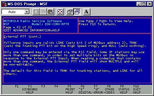
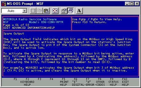
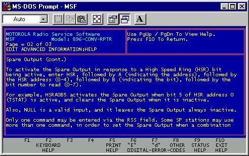
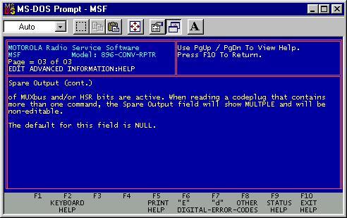
Here are the help screens and then some more discussion:
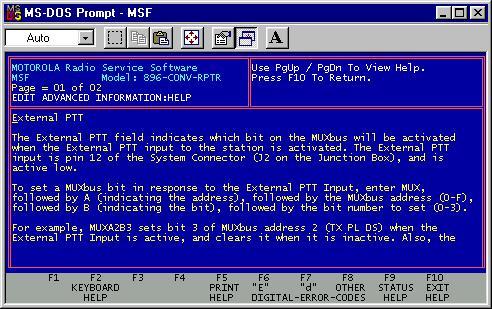
Hmmm,
So by reading these screens (and the nice example shown in the help file text), one could see that the External PTT Input (active low) could be used for almost anything else. The default programming for the External PTT Input is "LINE", which means grounding this pin causes a Line TX to occur. Since 99% of the amateur systems don't use a wireline control that means we can reprogram that pin without affecting anything else. It's interesting that the example shown is EXACTLY what I was looking for (kill the transmit PL encoder). Brings to mind the Elmer Fudd cartoon with the cry of the Valkyries Kill the wabbit!.
From WA1MIK:
'External PTT Input' is a poor name for this field and input
pin, as you can reprogram it to do more than just activate a PTT line. A better
name would have been 'Spare Input', to go along with the adjacent 'Spare Output'.
This field can be accessed on the bottom of the Advanced Information screen, page 8 (of 10).
But wait, now I need the secret decoder ring to figure out the bits. HMMMM, what about the front of the diagnostics panel?
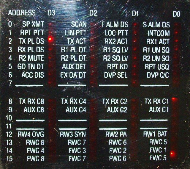
MUX A2B3 (Address Row 2, Bit 3 (zero relative)) is the interesting bit - look at that it even says TX PL DS (Transmit PL Disable)!! Cool !!!!
OK, part 1 is complete as I have the process and the decoder ring, so let's try something. On to part 2: how about using a COR or PL Decode signal to trigger the Transmit PL Encoder Disable function?
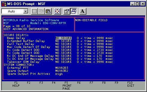
Use A3B2 for R1 PL DT (Receiver #1 PL Detect) for the spare output. In a carrier squelch receive setup you'd use A3B0 for R1 UN SQ (Receiver #1 unsquelched). The output signal appears on J2 pin 9. It can be set active high or active low (the default is active low) and in this case needs to be set for active high so that pin 9 goes high when the receiver detects coded squelch (PL or DPL). Voila!
From WA1MIK:
Some versions of TTRC firmware ignore the Active Level field
and the 'Spare Output' operates as if it is always programmed for Active High. This
works out fine for this article, but it could confuse the next person, so set the
field to HIGH, even though it may not matter on your station. This has been fixed
in TTRC Firmware version 5.41, which properly configures the Spare Output to be
Active High or Active Low.
So now TX PL DS (Transmit PL Disable) will follow the input signal: either R1 PL DT (Receiver #1 PL Detect) or R1 UN SQ (Receiver #1 Unsquelched) !!!!
So there you have it.
Program advanced menu page 8 as seen above and add a jumper from pin 9 to pin 12 of the external DB25. Now when there is no received PL on the receiver (or in the second case no carrier), pin 12 is low. As this is looped back and feeds into pin 9, the transmit PL encoder is disabled. Voila! The tech would have been in and out in 20 minutes and would look like a freaking genius! And with no hacking or slashing on the PC boards.
Next are the help screens from the spare output.
Note from the editor:
The MSF5000 Transmit Disable function, when activated, chops the
PL encoder signal off right now. There is no reverse burst
sent. This doesn't matter, as the transmitter will always be keyed
for several more seconds (i.e. for the duration of the carrier delay
timer, also known as the hang-in timer).
For additional information see the RSS manual snippet on the topic.
Summary:
| Bit to program to the spare output (pin 9) | |||
|---|---|---|---|
| Address Row and Bit |
Name | Function | Active High or Active Low |
| A3B2 | R1 PL DT | Receiver #1 PL Detect | Active High |
| A3B0 | R1 UN SQ | Receiver #1 UnSquelched | Active High |
The spare output comes out on pin 9, is looped back into pin 12, and can also be fed to an external repeater controller as a Receiver UnSquelched signal (RUS).
Note from the editor:
You can get COR from a test point in the station, program the Spare Output
as PL decode and use it as the PL input to an external controller. A Digital
Ouput from the controller could feed pin 12 (External PTT / Spare
Input). This would let you have the repeater controller programming turn on
and off the PL Encoder on the repeater transmitter at will.
The articles on repeater controller interfacing have more information on COR, etc.
| Bit to program to the External PTT (pin 12) (a better name would be "Spare Input") |
||
|---|---|---|
| Address Row and Bit | Name | Function |
| A2B3 | TX PL DS | Transmit PL Disable |
| The polarity is active low and cannot be changed | ||
Hope this helps.
>>>Lou N1UEC <<<
Contact:
Lou Harris N1UEC can be reached at his-callsign [ at ] n1uec [ dot ] org.
Bob WA1MIK can be contacted at: his-callsign [ at ] comcast [ dot ] net.
Back to the top of the page
Up one level (MSF5000 index)
Up two levels (Moto Index)
Back to Home
This page originally posted on 26-Nov-2009
Article text © Copyright 2009 by Lou Harris N1UEC.
Artistic layout and hand-coded HTML © Copyright 2009 and date of
last update by Michael Morris WA6ILQ.
The Repeater Builder's site does not evaluate the accuracy of materials created by persons beyond its control or supervision. Therefore, although this site links to many additional web sites, The Repeater Builder's site is not responsible for the availability of or the accuracy of any materials contained within those web sites.
This web page, this web site, the information presented in and on its pages and in these modifications and conversions is © Copyrighted 2009 and (date of last update) by Kevin Custer W3KKC and multiple originating authors. All Rights Reserved, including that of paper and web publication elsewhere without permission.