Up two levels
Back to Home
MSF5000 Squelch Circuits
By Robert W. Meister WA1MIK

|
Up one level Up two levels Back to Home |
Investigating the MSF5000 Squelch Circuits By Robert W. Meister WA1MIK |
|
The MSF5000 has two independent and slightly different squelch circuits. Both are located on the Secure-capable Station Control Board (SSCB) on the digital-capable stations or the Station Control Module (SCM) on the older analog (CLB) stations. One is called "Repeater Squelch" and the other is called "Receiver Squelch". OK, so the big questions are:
This article concentrates on the digital-capable (CLB/SSCB) circuitry.
How Squelch Circuits Work:
Detected audio comes in from the receiver. This signal is flat; no de-emphasis has been applied. In this case we want just the noise that resides in the frequency range of 5 kHz and above; any de-emphasis would have removed all of that. The signal is processed with high-pass filtering, amplification, and limiting to remove voice audio variations from the noise. The remaining noise signal is passed through a level-setting pot that presents it to a rectifier to produce a DC voltage proportional to the amount of noise present on the signal. This DC voltage is compared to a fixed voltage (threshold), and if there's more noise voltage present, the squelch stays closed. As the signal strength increases and the noise level decreases, the noise voltage goes below the squelch threshold and the squelch opens.
Common Circuitry:
Incoming detected audio enters at the point labeled "AA" on the left. Two op-amp stages provide filtering, gain, and limiting. The noise feeds two EEPots (Electronically Erasable Potentiometers), which adjust the noise levels. The Receiver Squelch can be adjusted via a front panel (mechanical) Squelch pot instead, which is activated when the front panel "ACC DIS" switch is raised. The noise runs through more filtering and finally a rectifier, which produces the DC voltage that's proportional to the incoming noise. Refer to the squelch circuit schematic below. Click on it for a much larger view.
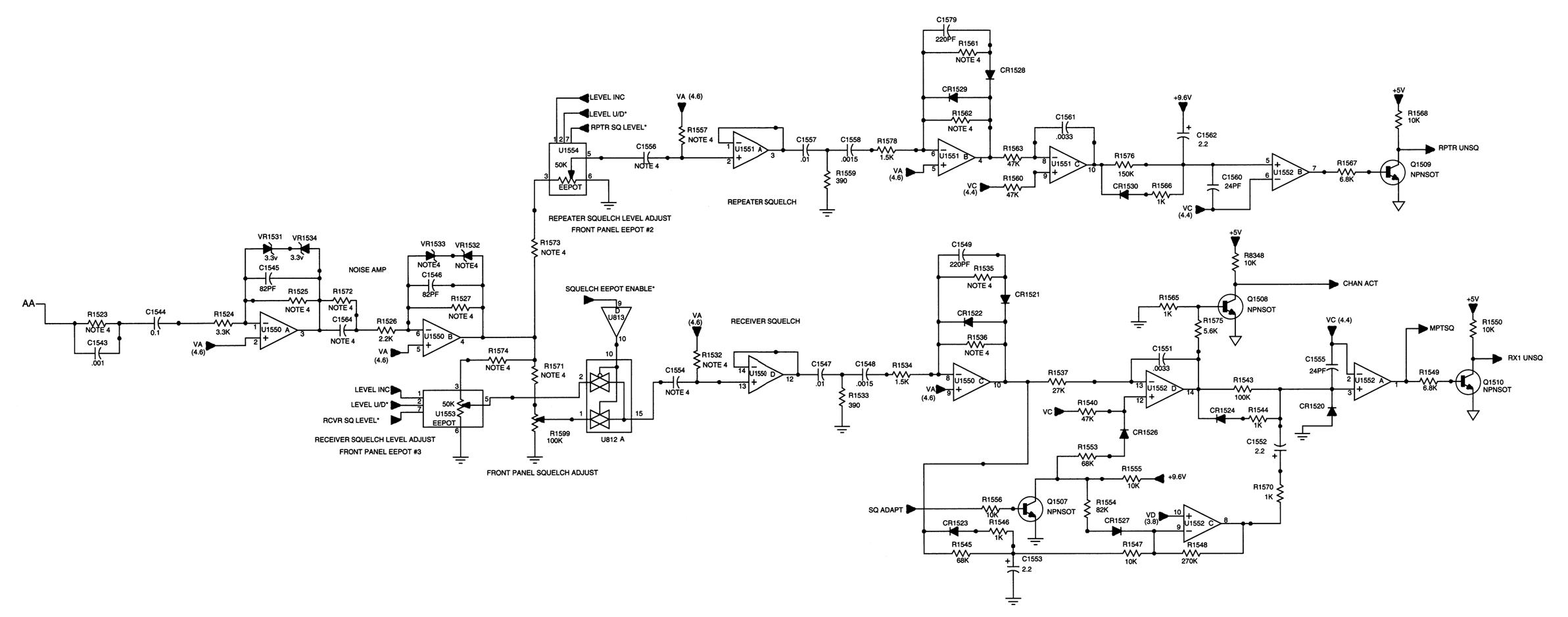
Repeater Squelch:
The upper portion of the schematic is the repeater squelch. According to the manual, the repeater squelch has a fast opening time and a slow closing time of typically 200 milliseconds. The opening time is determined by R1566 and C1562, while the closing time is determined by R1576 and C1562. The repeater squelch detector produces the RPTR UNSQ signal, which is high when a signal has opened the squelch and is low when the squelch is closed. It would seem that the repeater squelch has a longer tail to prevent the repeater signal from frequently dropping out. This squelch circuit is ONLY used by the station when it is configured as a repeater, i.e. it is automatically retransmitting anything that comes into the receiver. Repeater Squelch is adjusted via EEPot #2. Both the repeater squelch and the receiver squelch must close with no signal if you want to use the internal CW ID feature.
Receiver Squelch:
The lower portion of the schematic is the receiver squelch. According to the manual, the receiver squelch has a fast opening time and a variable closing time. The opening time is determined by R1544 and C1552, while the long closing time is determined by R1543 and C1552. With a receive signal just above the opening threshold, squelch closing is slow, approximately 150 milliseconds, which produces the long squelch tail heard at the end of a received message. The long tail is present to prevent the received message from being chopped during a weak fluttering signal. With a strong signal (approximately 10dB above threshold), the squelch closes immediately after the end of a received signal. This prevents the long and obnoxious squelch tail from being heard. The intent of this circuit is to mimic the operation of the famous MICOR squelch.
The receiver squelch detector produces two output signals: CHAN ACT and RX1 UNSQ. Both go high when a signal has opened the squelch and go low when the squelch is closed. CHAN ACT responds immediately with no closing delay. RX1 UNSQ has a closing time that depends on the signal strength, with a long squelch tail on weak signals. CHAN ACT is used primarily in channel-scan applications. This squelch circuit is used for all purposes except the internal repeater. This includes the wire line, local, and MRTI audio signals. Receiver Squelch is adjusted with EEPot #3 or the front panel SQU control. Both the receiver squelch and the repeater squelch must close with no signal if you want to use the internal CW ID feature.
The SQ ADAPT signal and related components force a fast squelch closing during channel changing to eliminate the squelch tail noise. For our purposes this circuitry can be ignored. However other components below the receiver squelch decide whether the squelch tail should be long or short, by controlling C1552.
Testing the Squelch Circuits:
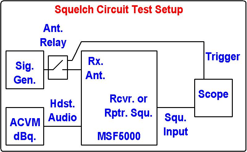
To test and measure the operation of the squelch circuits, I needed a way to turn the RF signal on and off and use that as the trigger to find out how long it took the squelch to open or close. None of my signal generators had a means of telling me when there was a signal present at the output or not, so I used the MSF5000's antenna relay to do the switching.
I connected an RF signal generator to the antenna relay input connector on the station. This relay was used to switch the antenna between the receiver and the transmitter in a base station setup. When energized, this relay disconnects the receiver input from the antenna and connects the transmitter output to the antenna. One side of the relay coil already went to +9.6V in the station; I just grounded the other side when I wanted to activate the relay, just like the station would have done. This ground also was used as a trigger signal to the oscilloscope. When the ground is connected and the relay is activated, no RF signal reaches the receiver and it squelches up. When the ground is released and the relay is de-activated, the RF signal passes through to the receiver and the squelch opens.
The AC voltmeter is connected to the Headset Audio signal on the SSCB. This audio is de-emphasized and squelched, and its level is adjustable via the front panel VOL control. The meter lets me set the RF signal level for any desired level of quieting, so I can determine the short/long squelch tail threshold. I adjusted the front panel VOL control for -10dBm on squelch noise with no signal. This is the reference level. When an input signal (without modulation) causes the meter to go to -30dBm, I know that the input signal is producing 20dB quieting in the receiver, and so forth.
The ACC DIS and PL DIS switches are activated on the station. This gives me manual control of the receiver squelch threshold via the front panel SQU pot. I recorded the input signal level when testing the receiver squelch; I used the same levels when testing the repeater squelch.
The oscilloscope monitors the RX1 UNSQ or RPTR UNSQ signals on U1552 pins 1 or 7 respectively. Note that the signals are inverted here: an open squelch condition produces a low signal at U1552's outputs; the transistors connected to those same pins inverts the signals. When the antenna relay is released (not grounded), the RF signal will be passed to the receiver, the scope will be triggered on the positive-going edge, and I can measure the squelch opening time as the time between the trigger and when the signal trace goes low. When the antenna relay is activated (grounded), no RF signal will be passed to the receiver, the scope will be triggered on the negative-going edge, and I can measure the squelch closing time as the time between the trigger and when the signal trace goes high. To repeat: when the relay is energized (its lead is grounded), the signal to the receiver is cut off, U1552's outputs go high, and the squelch closes. The diagram below shows the test setup.
Test Results:
Rather than bore you with a lot of scope traces, I've tabulated the data instead. I measured the squelch opening and closing times for both the receiver squelch (U1552 pin 1) and the repeater squelch (U1552 pin 7), at various levels of input signal quieting. The squelch pot was set at threshold for the receiver squelch via the front panel SQU pot; these readings are under the 2dBq columns. The repeater squelch was at the value it last had through RSS and this was apparently 7dB quieting. I repeated the receiver squelch measurements using a similar 7dBq value. The input level is the signal strength in dBm that was required for the decibels of quieting being tested. All times are in milliseconds. I took five measurements for each condition and reported the fastest.
| Input | dBq | Rx C->O | Rx O->C | Rx C->O | Rx O->C | Rp C->O | Rp O->C |
|---|---|---|---|---|---|---|---|
| Level | Squ: | 2dBq | 2dBq | 7dBq | 7dBq | 7dBq | 7dBq |
| -123 | 5 | 8 | 120 | - - - | - - - | - - - | - - - |
| -122 | 7 | - - - | - - - | 10 | 120 | 90 | 160 |
| -120 | 10 | 8 | 115 | 8 | 80 | 32 | 180 |
| -117 | 15 | 8 | 48 | 8 | 10 | 16 | 190 |
| -114 | 20 | 6 | 30 | 6 | 10 | 10 | 196 |
| -111 | 25 | 6 | 30 | 6 | 10 | 10 | 196 |
The receiver squelch open-to-close time is variable in the -123dBm to -117dBm input level range, representing 5-15dB quieting. The length of time increases as the signal gets weaker and the level of quieting gets lower. I stepped the input level in 1dB increments from -122 to -117dBm and the close times were 120, 100, 80, 60, 30, and 10 milliseconds, respectively.
I also took some DC voltage readings at a few points in the receiver squelch circuit with the same input and quieting levels as above; these have been tabulated below. Many of the readings fluctuated by several hundred millivolts due to the noisy signal. The VAC column is the peak-to-peak voltage on U1552 pin 8. This controls the variable squelch release time.
| Input | dBq | U1550-10 | U1552-14 | U1552-8 | VAC |
|---|---|---|---|---|---|
| None | 0 | 4.34 | 7.62 | 7.92 | 0.1 |
| -123 | 5 | 4.39 | 2.22 | 6.10 | 1.7 |
| -120 | 10 | 4.42 | 0.17 | 4.60 | 1.3 |
| -117 | 15 | 4.45 | 0.05 | 3.20 | 0.7 |
| -114 | 20 | 4.48 | 0.04 | 2.00 | 0.1 |
| -111 | 25 | 4.51 | 0.03 | 1.57 | 0.1 |
Conclusions:
The descriptions in the manual don't specify how fast the squelch opens, but my tests showed this to be 5-10 milliseconds after carrier was applied. The receiver squelch seems to work about as described with a longer squelch tail taking effect around 10dB quieting, however the fast squelch tail mode was still rather long at 30-50 milliseconds with the squelch set at threshold.
With the receiver squelch set at threshold (barely closed) and able to open on a 5dB quieting signal, there was a lot of variation in the opening and closing times. The repeater squelch was considerably tighter and it required a 7dB quieting signal to open, however the readings were very consistent. After I adjusted the receiver squelch to the same setting (opening at 7dB quieting), the results were much more consistent, like they were for the repeater squelch. Under this condition, the fast squelch tail length was reduced to 10 milliseconds, which is certainly good enough to be called "fast". The closing time varied between long and short as the input signal varied between 5 and 10dB quieting.
If you want the benefit of a short squelch tail when the received signal is more than 10dB quieting, you should use the receiver squelch with an external repeater controller. This circuit is a very close functional equivalent of the famous MICOR M6709 squelch IC, however that IC abruptly switches between long and short at something closer to 20dB quieting. See this article that examines the M6709 squelch length timing.
It's interesting to note that Motorola normally designs its systems so the squelch doesn't open until the signal strength produces 20dB quieting. Amateur radio operators usually adjust the squelch so it's right at the threshold.
Acknowledgements and Credits:
The squelch schematic came from the Motorola UHF MSF5000 Service manual.
Contact Information:
The author can be contacted at: his-callsign [ at ] comcast [ dot ] net.
Article text, photographs, and hand-coded HTML © Copyright 2015 By Robert W. Meister WA1MIK.
Up one level (MSF index)
Up two levels (Moto index)
Back to Home
This article was created 16-May-2015
This web page, this web site, the information presented in and on its pages and in these modifications and conversions is © Copyrighted 1995 and (date of last update) by Kevin Custer W3KKC and multiple originating authors. All Rights Reserved, including that of paper and web publication elsewhere.