Up to the main Moto index
Back to Home
Design and Implementation by Henry Wingate K4HAL (k4hal at arrl dot net)
Photos by Hop Hays K4TQR
HTML'ized and edited by Mike Morris WA6ILQ

|
Up one level Up to the main Moto index Back to Home |
Adding a Homebrew Status Display Card to the Motorola MSR2000 Station Design and Implementation by Henry Wingate K4HAL (k4hal at arrl dot net) Photos by Hop Hays K4TQR HTML'ized and edited by Mike Morris WA6ILQ |
|
If you read the MSR2000 conversion article by K4HAL you will notice that he pulls almost all the cards from the card cage and connects his repeater controller to a pigtail cable that conencts to pins on the backplane. As such, the Squelch Gate card slot is empty.
Well, Henry created a piece of test equipment that may be useful to you. He took a timeout timer card and stripped the components from it, drilled holes in the front for the LEDs and wired them to a few resistors and to the pins on the card. As he says, "Really messy, but it is kind of useful to tell what is going on". His display card has LEDs for DC power, Carrier (COR), PTT, and PL decode.
If you convert your MSR and do end up using the Squelch Gate card slot, the same fuctionality could be implemented on the squelch gate card itself using the information and schematic below. To save space on the squelch gate front panel you could locate the DC Power and PTT indicator LEDs on the front panel of the Station Control card (thanks to Neil McKie WA6KLA for the suggestion).
But enough digression - the photos are all you will need to duplicate Henry's test card. The photos below are thumbnails, click on any of them for a full size image.
A note from WA6ILQ:
I built one of these for a friend's MSR, the only changes I made were due to the fact that
my friend had plans for the Squelch Gate slot and that I had an assortment of LEDs in the
junk box. I used a green LED for power, red for PTT and yellow for both COR and PL
decode. As I needed to find a different location for the indicators I put the power
on indicator (a small green LED) and the PTT indicator (a small red LED) on the front of the
Station Control card. I bent up a scrap of aluminum as a front panel for the slot to
the right of the PL card and mounted a piece of perfboard to the backside of it for the
transistors and resistors. A length of ribbon cable was routed up and over the edge
of the backplane. I soldered the individual leads from the ribbon cable to the pins on the
backside of the sockets for the Station Control card and the Squelch Gate card.

The card cage with the display card sitting in the squelch gate slot (81kb)
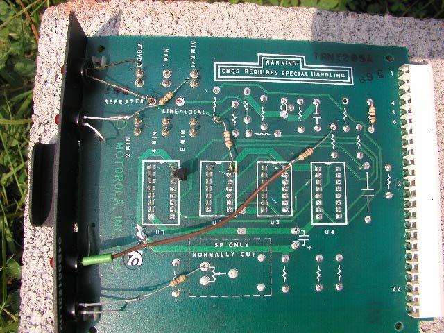
The component side of the display card (98kb)
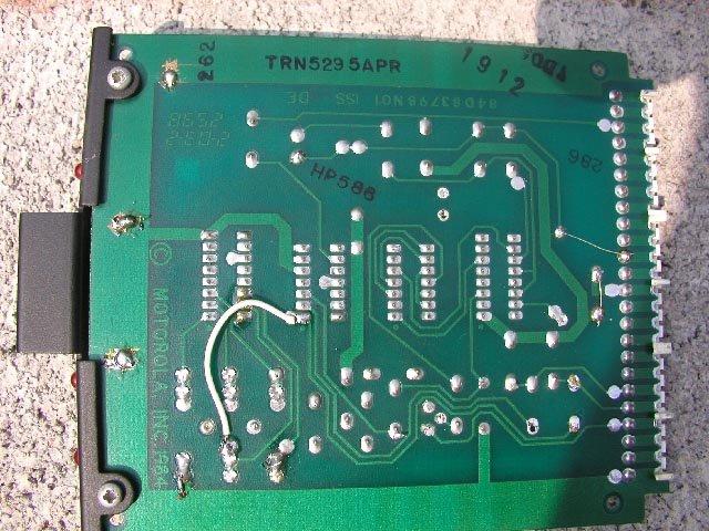
The foil side (93kb)
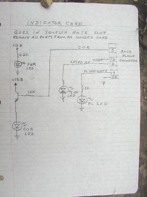
The schematic (76kb)
Technical work by Henry Wingate K4HAL (k4hal at arrl dot net)
Photos by Hop Hays K4TQR
HTML and all text by Mike Morris WA6ILQ
Last modified 12 September 2003
Note from WA6ILQ:
If you see something above that is vague, missing (or outright wrong),
please let me know! It's input from the readers that make these
writeups better. I can be reached via either an email
or snail mail address that is available via the qrz web site.
(I've included the QRZ link above instead of my real snail mail and email address since my first household move in over 25 years is coming up, and modifying all the web pages at my own schedule over six months saves having to update a lot of web pages at once).