Motorola index
Back to Home
the Motorola® Quantar® station
Originally by Author Unknown
Reworked with new images by Robert W. Meister WA1MIK (SK)
Currently Maintained by Mike Morris WA6ILQ.

|
Quantar index Motorola index Back to Home |
Introduction and Interfacing of the Motorola® Quantar® station Originally by Author Unknown Reworked with new images by Robert W. Meister WA1MIK (SK) Currently Maintained by Mike Morris WA6ILQ. |
|
Mike has very little hands-on experience with this equipment so please ask on the repeater-builder mailing list!
Note from Mike WA6ILQ:
An envelope without a return address showed up in mid-April of 2005 at my QRZ snail-mail address. It contained a floppy disk that had a Word file and some JPG image files. The note included stated that the author worked for Moto however had to have anonymity to keep his job. At the time this article was created I'd not been inside a Quantar nor seen any of the manuals.
The Motorola Quantar® / Quantro® family is a very capable station and available off the shelf in amateur 2m, 440 and 900 MHz frequency bands. The Quantro is essentially a high power version of the Quantar with an external PA deck. As of the time of this writing the Quantar / Quantro is the current high-end unit of the Motorola fixed station product line and is available in several configurations handling conventional and trunking installations. For our purposes we will be looking for a Quantar that is not classified as an "IntelliRepeater®" (IR) or an "Intelligent Site Repeater®" (ISR) as they will not function as conventional repeaters without firmware changes. You want a conventional or SmartNet capable station. Most of the newer stations are Astro Digital® capable (APCO Project 25 Common Air Interface). Depending on the version of PA, they are capable of low power (20 watt) operation up to the standard high power PA at 110 watts for UHF and 125 watts for VHF. Quantros can be capable of up to 250 watts.
The general specifications of the Quantar stations are shown below. Click on any of the bordered images to see a larger view.
The receiver specifications are shown below.
The transmitter specifications are shown below.

The stations are capable of operating either as a repeater (Full Duplex) with in-cabinet repeat, or as a base station (either half or full duplex). They have built in CWID functionality as well on a programmable interval of 5 to 60 minutes. For Quantar stations to operate as a half duplex base station an external T/R relay controlled by J23 is needed for single antenna operation.
With a wireline board installed the stations are also capable of either programmable TRC (Tone Remote Control) or DC control operation.
A wireline card is required to use the station with external audio and PTT. These cards come in either a 4 wire or 8 wire type and either will suffice for an external controller interface. You must enable wireline card in RSS before you can use it. Some advanced features are available only if you select 8-wire mode. For some controllers you can use a 4-wire connection but to use the features you need to tell RSS it is an 8-wire. All wireline and control signals are available from the back panel of the station at J17, which is a 50-pin telco connector. Audio is also available from connector 61 which is an orange block coming from a cable to the wireline board. Standard 4 wire designations are: Line1 is audio to the transmitter, Line2 is audio from the receiver. Audio line levels are software programmable and the transmit audio level will need to be calibrated to a standard tone level from the RSS alignment screens. The factory default programming is -10 dBm (test tone level) for transmit of 60% rated deviation, and -11 dBm (test tone level) receiver output level at full deviation. Remember that there is a 4.4 dBm difference between test tone level and peak audio level (-10 dBm test tone = -5.6 dBm peak).
The station can be programmed to use mixed mode (both analog and digital) operation but to use Astro Digital® modes from the wireline requires either an Astro Modem or V.24 daughter board for the wireline card, as well as an external DIU® (Motorola Digital Interface Unit) as the station does not do the A/D conversion. I believe the DIU requires TRC operation as well but don't hold me to it.
Programming and alignment of the Quantar station takes Motorola RVN5002 CPS. Early versions would not work on 64 bit windows. Version 14.10 and earlier allow wideband. The later CPS locked you into narrowband unless you had an entitlement key (and those are no longer available). I will not be covering programming or alignment for this document but will mention places where certain options must be programmed for a function. The stations do not require any modification to work on US amateur frequencies as long as the correct frequency range modules are in place.
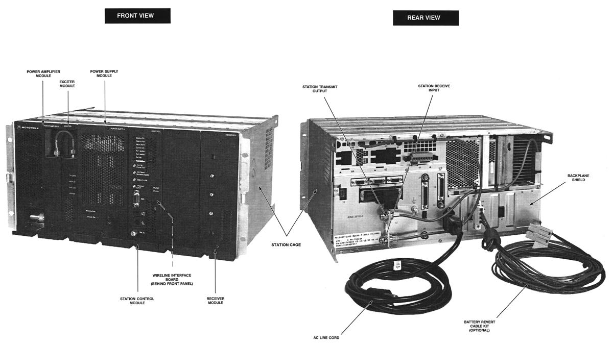
General Overview:
The image below shows the major assemblies and connectors. If anyone can provide information on the optional Battery Revert Cable Kit we'll add it to this page.
The image below details the front panel controls and indicators.

Interfacing to External Controllers:
The signals of interest for interfacing to an external repeater controller are: Transmit Audio, Receive Audio, COS, PTT, and Transmitter Inhibit. Programming of the station for base or repeater operation depends on the application. If you intend to use the station only as a transmitter and receiver with the external controller doing the work of PTT and audio switching, then base station operation is call for. If you will be using it as a standalone repeater with a feed from and IRLP node computer or link radio with no other external controller, then repeater operation would be preferred. Again, this is a highly programmable radio with many features and functions and by turning on the Wildcard option in the station it can be even more programmable but that is beyond the basic scope of this article.
All of the functions described below are available by default without any special programming.
Audio Wiring:
Line1 = Transmit Audio: balanced 600ohm (requires PTT from J17 to pass wireline audio to the transmitter).
Line2 = Receive Audio: balanced 600ohm.
External PTT:
PTT requires applying ground to J17 pin 47. Ground is found on J17 pin 7.
A jumper between J17 pins 8 (+5VDC) and pin 22 (EXT PTT +) is required. This is an opto-coupled input.

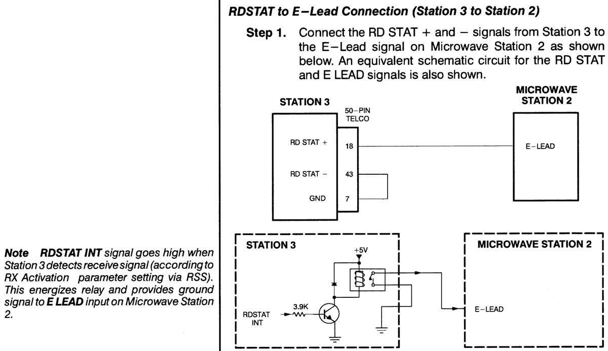
COS:
A receiver unsquelched (RDSTAT) indication is available from a relay closure located at J17 pins 18 and 43. See the RD STAT E-Lead connection diagram below for more circuit details.
Transmit Inhibit:
Applying a ground to J17 pin 12 will place the station in a transmit-inhibit state. The receiver will still be active and pass audio to the wireline output. This is a transistor buffered input. This may not be necessary if you use an external repeater controller.
External Frequency Reference:
If you have a site standard frequency reference such as a GPS or rubidium oscillator, you can use J30 to insert a 5 MHz or 10 MHz reference signal. Injection levels are expected to be 1.0V RMS +/- 0.5V. To use an external reference it is necessary to program the station in the SERVICE / HARDWARE CONFIGURATION screen of RSS and set it to EXTERNAL 5MHZ or EXTERNAL 10MHZ Frequency Reference. Do not inject an external reference with the station programmed for internal or you will have issues with the two oscillators beating against each other.
Rear Panel Connectors:
For some reason, Motorola numbers all the connectors, while the documentation uses large letters to identify them. The descriptions luckily contain both, but they're in no particular order. Here's an image of all the rear panel connectors.
Connectors "A-H" are described below.

Connector "I" is described below.
Connectors "J-M" are described below.

Connectors "N-Q" are described below.
Acknowledgements and Credits:
All of the images came from the Quantar Digital-Capable Station Instruction manual, p/n 6881095E05-D, which covers VHF, UHF, 800 MHz, and 900 MHz Conventional, SECURENET, ASTRO, 6809 Trunking, and IntelliRepeater systems. At the time this article was revamped, the manual could be bought from Motorola for about $77US.
Motorola, Quantar, Quantro, SECURENET, ASTRO, IntelliRepeater, and a whole bunch of other terms are trademarks or registered trademarks of Motorola, Inc.
Contact Information:
The original author is Author Unknown.
You can contact Bob at: his-callsign [ at ] comcast [ dot ] net, but he doesn't know
anything about Quantars, so don't ask.
NOTE: Someone sent Bob an e-mail suggesting that some of the information presented herein was incorrect. Unfortunately, that person could not be contacted for further details so I can't confirm the accuracy of his claim.
Back to the top of the page
Up one level (Quantar index)
Up two levels (Motorola index)
Back to Home
This page originally posted on 30-May-2005
This page reworked and new images added 01-Sep-2009
Original article text and artistic layout © Copyright 2005 by Mike Morris WA6ILQ.
Images scanned and text edited / updated © Copyright 2009 by Robert W. Meister WA1MIK.
Additional information added by Mike Morris WA6ILQ as it became available.
This web page, this web site, the information presented in and on its pages and in these modifications and conversions is © Copyrighted 1995 and (date of last update) by Kevin Custer W3KKC and multiple originating authors. All Rights Reserved, including that of paper and web publication elsewhere.