|
Up one level (Motorola Index) Back to Home |
The Quantar & Quantro Station and Astro-Tac Receiver Index Page Originally Compiled by Robert Meister WA1MIK (SK) Extinsively Added to by Michael Morris WA6ILQ. Currently Maintained by Michael Morris WA6ILQ. |
Mike has little hands-on experience with this equipment so please ask on the repeater-builder mailing list!
Contributions, comments / critiques / suggestions / corrections / updates for this page (or any page) are welcome and appreciated.
Actually that applies to any page at this web site! (even one that just points out a typo).
The Astro-Tac Receiver is essentially a standard Quantar receiver module and a Station Control Module in a rack-mount box that is 2 Rack Units (3.5 inches) tall.
Here are some of the major differences between the Quantar and the Quantro:
As of December 31, 2020 the Quantar / Quantro product line is no longer supported by Motorola.
The manufacturing nameplate on the Quantars generally shows a Model T5365A along with the serial number. Astro-Tac receivers usually show T5367 or T5589. There is NO way to find out if that unit is VHF, UHF1, UHF2, UHF3, UHF4, 700, 800 or 900 MHz from the manufacturing plate without powering it up and downloading the codeplug but you can get some idea just by looking at the front of the receiver module: You will see either five holes or no holes. The VHF receivers have the preselector adjustment screws visible in all five holes (but you won't know what range the receiver is (132-150 MHz or 150-174 MHz). The UHF receivers (like in the photo at the top of this page) have the same five holes but only the three middle holes have the preselector tuning screws visible, but again you won't know which range the receiver was made for (403-433 MHz, 440-470 MHz, 470-490 MHz or 490-520 MHz). If there are no adjustment screws or no holes it's 700, 800 or 900 MHz.
Here's a photo of a VHF receiver module with the front sheet metal panel missing. The preselector modules are the same as the ones used in the MTR2000 / MTR3000 repeaters.
The Quantar / Quantro receiver module does not have a discriminator output. The module presents the recovered audio / data as two separate digital byte streams to the Station Control Module (SCM). Some digital magic inside the SCM recovers the audio or data.
On a new-to-you Quantar you will have to pull the individual modules out of the chassis and copy all of the (3 or 4 letters plus 4 or 5 numbers) part numbers off of the back of the modules, and then look them up to find out what you have. Then look at the known modules list sorted by number (there is another list linked below that is sorted by name).
Despite what you read elsewhere the Quantars and Quantros were never intended for GMRS. They are certainly capable, and can be set for the 50 watt limit, but Motorola never certified them for FCC Rule Part 95 (GMRS) service. See the FCC Designation information on page 22 of this file.
The published Quantar ranges are as follows:
VHF Range 1: 132‑154 MHz.
VHF Range 2: 146‑174 MHz. This range will work down to 144 MHz.
UHF Range 0, 380‑433 MHz This range was added last (chronologically), hence the Range zero.
UHF Range 1, 403‑433 MHz
UHF Range 2, 438‑470 MHz
UHF Range 3, 470‑494 MHz TV channel 14 is 470‑476, 15 is 476‑482, 16 is 482‑488, 17 is 488‑494.
UHF Range 4, 494‑520 MHz TV channel 18 is 494‑500, 19 is 500‑506, 20 is 506‑512, 21 is 512‑518, 22 is 518‑524.
800 MHz: RX on 806‑825 MHz, TX on 851‑870 MHz
900 MHz, RX on 896‑902 MHz, TX on 935‑941 MHz The RX upper limit can be hexedited to go above 902 MHz and the TX lower limit can be hexedited down to 927 MHz.
The spec sheet says that the receiver front ends are 4 MHz wide on VHF and 6 MHz wide on UHF.
Motorola made a kit of two brackets (0785412U01) that would center the Quantar (front-to-back) on a two-post rack.
Programming:
You'll need the RVN5002 "WinRSS" to progam the Quantar and Quantro stations and the Astro-Tac receivers (sometimes referred to as the ASTRO-TAC 3000). The Astro-Tac is essentially a Quantar receiver and a receive-only controller in a rack-mount box and was originally designed as a voting receiver but showed up in a number of other roles. Like the CPS for the R1225 and the MTR2000 / 3000 the Quantar RVN5002 will not run on 64-bit Windows. Also, the later versions locked you into narrowband unless you had an entitlement key (and as
far as I know those are no longer available). Revisions 09.07.00, 14.08.01 and 14.10.00 are "out there" however 14.12.00 is the one that you want to look for. Anything later forced the unit into narrowband. The final version was R14.13.00.
The Quantar SAM has it's own RSS, part number RVN4110.
If any additional information is received I'll add it here.
You program the Quantar through the 9‑pin female connector (DE‑9 / DB‑9) on the front of the station control module (SCM). The programming cable is Motorola's part number 30‑80369E31 or E32 but you can make one yourself, no RIB is used, it it a simple null-modem connection and has a DE‑9 (nine-pin female) on the computer end and a DE‑9 (nine-pin male) on the Quantar end:
Computer end   |        Quantar end
9 pin female   |        9 pin male
               |
  2 --------------------- 3
  3 --------------------- 2
  5 --------------------- 5
  7 --------------------- 8
  8 --------------------- 7
               |
In most cases 7 and 8 won''t be needed... all that you will need is a three-conductor "null modem" connection (pins 2, 3 and 5) (with 2 and 3 swapped on one end).
Both ends have no connection on pins 1, 4, 6, and 9.You can help to minimize the number of cables you have to keep in your radio programming laptop computer bag... Just find a tiny 2PDT toggle switch that fits inside the 9-pin cable shell. Just wire it so that in one position it's a 2-3-5 straight through extension cable and the other position 2-3 are swapped for a simple null-modem connection. Or use a 4PDT toggle switch and swap 7-8 also. Label the switch as "Extension" and "Null".
Power Supplies:
The Quantar power supply modules come in 3 generic versions (and a couple of sub-versions):
One of the Motorola Quantro rack-mounted power supplies is the TPN1186B... originally spec'd for the MSF5000 station.
It is rated at 14 volts and 35 amps continuous duty and weighs about 50 pounds.
Photo 1
Photo 2
Photo 3
| Quantar Power Supplies Comparison | ||||||
|---|---|---|---|---|---|---|
| Part Numbers | Power Input1 |
Manufacturer2 | Battery Revert / Battery Charger3 |
Watts4 | Other | |
| OEM | FRU | |||||
| CPN1031 | TLN3377 | 43/62v DC at up to 22 amps | Motorola | N/A | 600 | Output: +28.6v at 12.5a, +14.2v at 8a and +5.0v at 3A |
| CPN1041 | ? | AC | Onan | ? | 700 | |
| CPN1042 | ? | AC | Onan | ? | 700 | |
| CPN1047 | TLN3259 | AC | Motorola | No | 625 | Output: +28.6v at 12.5a, +14.2v at 8a and +5.1v at 3a |
| CPN1048 | TLN3260 | AC | Motorola | Yes | 625 | Output: +28.6v at 12.5a, +14.2v at 8a and +5.1v at 3a |
| CPN1049 | TLN3261 | AC | Motorola | No | 265 | Output: +14.2v at 12.5a and +5.1v at 9a |
| CPN1050 | TLN3262 | AC | Motorola | Yes | 265 | Output: +14.2v at 12.5a and +5.1v at 9a |
| ? | TPN6184 | AC | Motorola | ? | 625 | |
| ? | TPN6185 | AC | Motorola | Yes | 625 | |
| TRN7801 | TLN3263 | 21.0-34.5vDC at up to 40 amps (24vDC) | Onan | N/A | 600 | Output: +28.6v at 16a, +14.2v at 9a and +5.1v at 9a |
| TRN7802 | TLN3264 | 10.5-34.5vDC at up to 8.5 amps (12 or 24v DC) | Onan | N/A | 210 | Output: +14.2v at 12.5a and +5.1v at 9a |
| TRN7803 | TLN3378 | 41-72vDC at up to 8.5 amps | Onan | N/A | 210 | Output: +14.2v at 12.5a and +5.1v at 9a |
If your Quantar has a Battery Revert power supply and you want to use that feature then you will need a Battery Revert cable kit (TRN5155A) to connect the Quantar to the battery. As of mid-2025 the TRN5155A cable was still available from Motorola Parts for about $120 (or you can easily build it!) if that cable is not present on the back of the chassis in
connector location 25 (opens in a new browser tab).
The Battery Revert cable has an 8-pin (2 sided, 4 pins per side, the 2 sides are paralleled) card edge connector that bolts into location 25. The cable has a large ferrite bead next to the card edge connector (anyone
have an idea of where to find the beads?). The 8-gauge (AWG) cable is about 9 feet long and the cable kit comes with a fuse holder to be placed in line with the positive lead. The high power Quantar uses a 60 amp 300 volt
fuse (low power is 15 amps or 20 amps). The fuse holder is not shown in the photos here:
Photo 1
Photo 2
Photo 3
Photo 4
Photo 5. (all open in new
browser tabs)
You may find that connector location 25 is open or may be capped with a metal
plate (a good idea to keep the mice out). If the plate is there you will want to save the screws, they are 3.5mm metric and
not every hardware store has them. And that leads me into the next paragraph...
The Battery Revert feature includes a built-in under-voltage battery protection circuitry (low voltage disconnect)
which triggers when the battery voltage drops to 10.75 volts (one manual says 10.5 volts) or 21 volts
on the high power stations. This disconnect protects the battery from fatal over-discharge. The Battery Revert power supplies have a charger and that should not be considered as the primary battery charger, they are essentially
a trickle charger. For sites with frequent AC Mains power interuptions Motorola recommends an external
battery charging system based on a switched mode charger made by Argus Technologies in Britsh Columbia,
Canada (we are looking for which Argus model was recommended)
The MTR page at this web site has some Argus information that might be useful.
(all of the links in this paragraph are off-site pointers, all open in new browser tabs)
The DC input connector that mounts in location 25 is an AMP/TE 530521-3 four position (8 contact) connector body. The contacts are
AMP/TE 5-530519-2.
Both Digikey and Mouser stock the pieces: Digikey's page for the connector body and the pins. Mouser pointers: body and pins. I could not find the plastic key (or tab) at either Digikey or Mouser but you could easily make one, perhaps by cutting a piece out of an old credit card or some other piece of sheet plastic.
The screws that fasten the connector into the back of the Quantar chassis are 3.5mm diameter and 12mm long.
Well, 3.5mm is NOT stocked at any hardware store near me (they had 3mm and 4mm) or at Home Depot or Lowes.
But they had them on Amazon....
https://www.amazon.com/dp/B07KY8H26C.
Yes, it's 10 pieces and they are Torx but it's the correct length and size... and at $8 it was cheaper than ordering a smaller quantity at a higher price from an internet hardware supplier and I already had the correct Torx driver in the set from when I first got started in Maxtracs.
The TKN8786A Battery Temperature Sensor Cable plugs into the 3-pin conector at connector
location 24 (adjacent to the Battery Revert connector). Unfortunately as of late 2025 that
Sensor Cable is no longer available from Motorola Parts. That cable is a small diameter grey cable
that terminates in a length of black heat-shrink. Inside / under that heat shrink is a
thermistor. The idea is that you would place the thermistor in direct contact with the battery so that
it measures the battery temperature, and that information would let the battery charger board inside
the power supply module adjust the charging current and voltage. An acquantance said that he's seen
the thermistor duct-taped to the negative post of a battery instead of to the plastic case of the battery...
the idea is that due to thermal conduction the metal post would be closer to the internal termperature
of the battery than the outside of the plastic case would be.
Any additional details that would help someone replicate the TRN5155A or TKN8786A cables would
be welcome....
Motorola says this about the X30 option "Battery Charger and Emergency Reverting":
Provides an adjustable, regulated power supply to trickle charge a battery, and automatically reverts to battery operation upon loss of primary power. This option is not recommended in situations of frequent AC power interruptions, due to the limited recharge capability of the Quantar / Quantro power supply. This option is not available on 350 watt models.
External storage batteries attach to the station through the battery connector at location 25 on the backplane. Includes a low voltage disconnect feature, which disconnects at 10.5 volts for 12 volt batteries, and 21 volts for 24 volt batteries. Requires only 12 volt batteries for 20 and 25 watt models and only 24 volt batteries for 100, 110 and 125 watt models.
Note: Output power may be reduced up to 3dB in the battery revert mode to conserve battery life. Full rated RF power is only available for terminal voltages of 13.5 to 15 volts (12 VDC: X30 option) and 27 to 30 volts (24 VDC: X30 option) at the station DC input connector.
Quantar Speaker:
The Quantar internal speaker is driven by a low power audio amplifier delivering pretty-much a line level output to a tiny speaker. Motorola provided a 4-pin modular test SPKR jack on the front of the the Quantar control module and specified a kit consisting of an amplified speaker and a cable that connected it to the Quantar or the MTR2000 / MTR3000 repeaters. The Volume Up and Volume Down buttons on the front of the control module provide 16 levels of volume on both the internal and external speakers.
The 4-pin modular P5601 SPKR connector on the Quantar is NOT a common RJ-11 / RJ-12 / RJ-14 style connector. Instead it is an RJ-9 / RJ-10 / RJ-22 (they are all the same 4-pin connector body) and is most commonly (at least in the USA) found as the narrow modular connector used on the curly cord used on wired telephone handsets.
The external speaker kit that Motorola specified was built around an amplified speaker that was already in production and used with a mobile handheld charger. The HSN1000A (or B or BR, or the HSN1006A) had a 6-pin Molex connector on it that was used for audio in, audio ground, +12vDC power in, power ground, and a pair of pins that were jumpered together... one was the actual speaker, the other was the ouput of the audio amplifier inside the speaker housing (there was a public address switch kit that replaced the jumper). The kit also included the 0185180U01 speaker cable that can be homebrewed and modified for the handset connector.
Amazon has the RJ-9 / RJ-10 / RJ-22 connector and crimp tools. Rather than buying them a the simplest way to find a mating cable is to recycle a wired telephone handset cable (it has the correct connector on both ends), is 4 conductors, and the color code varied with the manufacturer).
An acquaintance built himself an amplified speaker kit using a Western Electric #106 or #107 amplified speaker that could be powered from the +12vDC on the test SPKR jack on the front of the the Quantar control module. He added the handset connector from a regular desk telephone into the side of the speaker housing and then used the curly handset cord to connect the amplified speaker to the Quantar station.
Alternatively a common personal computer amplified speaker will work just fine, look for one that uses +12 to +14 volts (some are, some are powered by a 5 volt wall wart, some are powered from a USB jack - also 5 volts... You can find +5v on pin 8 of J17, ground is adjacent on pin 7). You can determine the pinout of the Quantar front panel SPKR connector with an ohmmeter, connect one lead to chassis ground, use the other to probe the pins on the SPKR jack (with the Quantar unplugged!)... The end pin that is grounded is pin 1, pin 2 is 14 volts DC to power the amplified speaker, pin 3 is audio ground, pin 4 is the line audio output (max about 1.4-1.5vpp).
Test Microphone:
The test microphone jack on the front of the Quantar is NOT an 8-pin RJ-45
style - it is a 6-pin(!) RJ-11 / RJ-12 / RJ-14 style socket, .
The Quantar documentation calls for a TMN6124 or TMN6164 handset or an
HMN1001 microphone – that is a regular mobile microphone except with
a 6-pin plug on the radio end of the curly-cord.
The HMN1001A microphone was originally used on both the Mostar and Traxar (a trunking
Mostar) mobiles, and later on both the HT-90 and HT-440 Converta-Coms (mobile handheld
chargers), and both the MSF and Quantar stations. These days the TMN6124 handset or
HMN1001 microphone is not very common, however it is worth acquiring one as a test
unit for your Quantar toolkit. You can modify a super-common and cheap HMN1056
series microphone that was used with the
Maxtrac / Radius / GM300 mobiles (it has an 8-pin RJ45-style
cord) and swap the cord to a 6-pin cord. The part number for
the 6-pin cord is 30-80146D02
(thanks to Andy NC4AB for that number) and was about $55 in the 2005 price list.
If you can't locate a 3080146D02
microphone cord there are 6-pin microphone curly cords made for Kenwood mobiles
(like the TK-705 / 780 / 805 / 880) that should be adaptable.
We would still like to find the HMN1001A (or B) info sheet that Motorola packed with the
microphone and scan it to PDF so we can make the full info available here.
Interfacing to External Controllers:
The Quantar / Quantro stations are capable of operating either as a full duplex repeater with in-cabinet repeat, or as a half or full duplex station.
The full duplex repeater with in-cabinet repeat uses the functionality of the Station Control module. They can be programmed with a Carrier Delay (also called a hang-in-timer), a Timeout Timer, and a CWID function with a programmable interval of 5 to 60 minutes. There is no internal DTMF decoder. You can turn the the repeater off and on by simply grounding or ungrounding pin 12 (the Transmit Inhibit pin) on the J17 connector on the rear of the Quantar chassis.Interfacing to an external repeater controller requires placing the Quantar into full duplex mode with in-cabinet repeat disabled and connecting an external controller to connector J17.
The Quantar / Quantro "System Connector" at position J17 is the main point for connecting external hardware to the Quantar / Quantro station.
That 50-pin / 25 pair connector was used heavily in the telephone industry since the late 1940s (yes, over 65 years) and is known by several names. Amphenol calls it a "101/111/112 series" and also a "Blue Ribbon" connector. AMP second sourced it as a "Champ .085" connector. Both are available in multiple sizes: 14, 24, 36, 50 and 64 pins. The telephone industry used a 25 pair male connector on every every multi line office desk telephone from the 1950's onwards, and also under the name "RJ-21" to connect from 1 to 25 analog phone lines or 12 four-wire digital circuits (56K, T1 or ISDN) phone lines to PBX systems.
There are web pages that call the 50-pin connector a Centronics conector. They are wrong. The Centronics parallel printer interface connector (IEEE 1284) used a 36 pin version.
Other web pages call it an "HP-IB" or "GPIB" or "IEEE 388" interface connector, but those are also wrong as they used the 24 pin version.
Other web pages call it a "SCSI" connector as they were used in the 1st generation desktop computer systems to connect everything from tape drives to external hard drives to flatbed scanners to... and SCSI has used a half-dozen different connectors.
Back to Quantars...
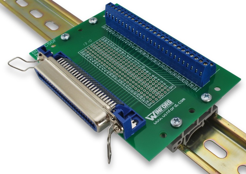
Winford Engineering (at https://www.winford.com)
makes a number of intefacing devices, one of which is
an RJ-21 termination / test
breakout module that I have used over the years when working on PBXs and key systems.
The Winford adapter
(larger photo of
the DIN rail version) has an Amphenol 50-pin female connector and two 25 screw
terminal strips that allow connecting to every pin. You can connect it to the Quantar with a
length of a male-to-male 25-pair telephone cable.
Winford Engineering does not make a 50 pin male version however if
you ask the folks at
(https://www.winford.com) they will be
happy to sell you a kit of everything except the female 50-pin Amphenol right angle
connector. You then purchase a male right angle connector from Digikey (their part
number 1050RMA-ND)
Norcomp 112-050-113R001 and build the kit... when you are done you will have a neat adapter that will plug
directly into the back of your Quantar and present all 50 pins on the connector
to 50 screw terminals.
NOTE: Due to the swap between the female to male connector the silk screening on
the Winford board will be totally WRONG!!! You can wash off the white ink with
a paint remover then add some pTouch labels on the pins you need.
Once you have your final pinout determined you can pull the Winford adapter and
plug in a male 50 pin connector with solder pins... the
Norcomp
111-050-103L001 wired with your custom cabling.
A wireline card is required to use the station with external audio and PTT. These cards come in either a 4 wire or 8 wire type and either will suffice for an external controller interface. The wireline card is located inside the Station Control Module. You must enable wireline card in RSS before you can use it. Some advanced features are available only if you select 8-wire mode. For some controllers you can use a 4-wire connection but to use the features you need to tell RSS it is an 8-wire. Line1 is audio to the transmitter, Line2 is audio from the receiver. Each is presented as a balanced pair, You can ground the – side and use the + side as hot, or use J17 pin 30 as the receive audio, and J17 pin 5 as transmitter audio, or pin 9 as a flat audio input.

|
An Overview and Beginner's Guide
to Interfacing the Quantar station Reworked by Robert W. Meister WA1MIK Images show the major assemblies and all rear panel connectors. Describes the most common interfacing signals. |
|
|
Interfacing The Motorola Quantar To The Arcom RC210 (off-site pointer to the Arcom web site) The Arcom RC-210 interfaces similarly to other external repeater controllers (i.e. the RLC and Scom). This article has a set of RSS screenshots on programming the Quantar. |
Articles and Brochures:
|
|
Ordering a Quantar Station Compiled
by Robert W. Meister WA1MIK A list of the major categories one would need to specify if ordering a new station. Now you can understand why model numbers are so hard to come by and could be nearly meaningless. |
|
|
General Quantar
Info from Motorolas Electronic Catalog 175 kB PDF file Equipment, options, descriptions, and prices. From September 2003. |
|
|
VHF Quantar Station Specifications brochure 266 kB PDF file dated 2004 |
|
|
UHF Quantar Station Specifications brochure 98 kB PDF file dated 2002 |
|
|
VHF-UHF-800 MHz Quantar Station Specifications brochure 2 MB PDF file dated 2004 |
|
|
800 / 900 MHz Quantar Data Base Station Specifications brochure 84 kB PDF file dated 2004 |
|
|
Quantar and Astro-TAC Receivers Specifications brochure 110 kB PDF file |
|
|
Identifying a Quantar Station
Submitted by Martin A Flynn W2RWJ Useful information and selection suggestions, plus lists of module numbers. |
|
|
Quantar Field Replaceable Units Compiled by
Robert W. Meister WA1MIK Lists of the various FRU part numbers with some context information which should tell you what your station is equipped with. |
|
|
Quantar OEM and FRU modules sorted by module number Compiled by Michael Morris WA6ILQ A table of the OEM and FRU module numbers sorted by module number. Modules with multiple numbers are listed by each number (multiple times). |
|
|
Quantar OEM and FRU modules sorted by module name Compiled by Michael Morris WA6ILQ A table of the OEM and FRU module numbers sorted by module name. |
|
|
Quantar Enhanced Wildcard Features Without Leaving In
The Enhanced Board Submitted by Josh Heide K6ZRX This programming feature was discovered purely by accident, but it opens up possibilities. |
|
|
Quantar
VHF Range 2 to Range 1 Amateur Band Modification Submitted by Rob Lee K7TGU Rob refered to this as "One quick approach, a Rough Draft" but it's complete. |

|
One person reported "I was able to convert/tune a VHF R2 range receiver down to 144 MHz. Looks like the receiver has two VCOs, one for each of the ranges, high and low. When I tried to program it below 145.6 MHz the RX1 indicator flashed red. I figured the VCO was out of lock. There are two coils in one shielded section of the receiver PC Board which I found to be the VCO coils. I'm not sure yet which one is which, but I tuned each one turn clockwise then the RX1 indicator went green. I was able to tune the R2 preselector with no problem down to 144 MHz. There was no issue using the high range exciter and PA down to 144 MHz." |
|
|
The Transmitter audio input impedance is unusually low, about 500 ohms. Some external audio sources (like some amateur radio repeater controllers) do not have sufficient audio level. This can be cured with an external amplifier, or modifying the external device for a higher level. |
|
|
The Motorola 9175300H02 (opens in a new browser tab) VHF 144-160 MHz 100 watt Duplexer option for the Quantar or GTR Repeater WILL NOT work in a 600 KHz receiver‑to‑transmitter situation. This is a $1400‑$1500 dollar option that is effectively a chinese knockoff (made by Fingu) of a Celwave / RFS PD5042 family duplexer and has a minimum channel spacing of 1.5 MHz. Go read this page for the full story on Fingu. (off-site pointer, opens in a new browser tab) |
|
|
Likewise the Motorola 0185417U02 (opens in a new browser tab) VHF 144-160 MHz 100 watt VHF band-pass duplexer option X182AB for the Quantar, MTR2000 and MTR3000 repeaters also WILL NOT work in a 600 KHz receiver‑to‑transmitter situation. That unit is a relabeled chinese clone ("FINGU 29650003" (opens in a new browser tab) of a 6-cavity RFS/Celwave PD5042-1-50 unit that has a 1.5 MHz minimum transmitter to receiver separation. Any Telewave, Phelps Dodge, RFS or Cellwave duplexer is preferred over any Fingu. |
|
|
If you have a high power Quantar there is a fan in the power supply and two fans in your high power PA.
Don't let the fans die. It gets expensive if you do. The PA fans are NOT the same as the power supply fan. The fan in one of the power supplies was a 92mm square fan that is 20mm thick, 12VDC, 0.18A, 2900RPM, ball bearings, 3-wire fan (with a tachometer lead). A good replacement is the Mouser 664-D0912HBA73GLLF, and is less than US$15. When the PA fans die use two of the Qualtek FAD106025CBHW12A as replacements (60x60x25mm, 12 volt, ball bearing, 70,000 hours), available from Mouser as 562-FAD106025CBHW12A and under US$15 each. |
|
|
Repeater-builder received an email...
To: (repeater-builder staff) Subject: Quantar P.A. reflectometer issue... (something for the Quantar page) I've been a Land Mobile electronic technician for over 40 years, and have used your site for info many times. I'm presently employed as a county radio tech, and we are waiting on Motorola to switch us to a new system. So in the meantime they hired me to help maintain their present 800 MHz SmartZone trunking system that is still using 800 MHz Quantars. They have had a huge issue with the Quantar power amps going bad. What I've discovered is the reflectometer circuit on the low pass filter/coupler hybrid board in the 800 MHz P.A has printed resistors on the ceramic substrate that start changing value with increasing resistance, that causes the station to compensate until it burns up the P.A. or pops a transistor. The printed resistors dont look burnt, they just change value by aging I guess. My solution is to cut the circuit trace behind the RF choke on both forward and reflected sides, and solder in a 300 ohm chip resistor to fix the reflectometer. I could not find schematics on that board, so I assume Motorola kept them as proprietary..... I've seen this and fixed it in three different 800 MHz PA modules: CTF1091B, CLF1849A and TLF1930C. The Quantars that a ham will see are almost always VHF or UHF. I don't know if the design of the VHF and UHF P.A. modules has the same problem. Thanks for the website my friend!... |
|
|
W9CR's Quantar Wiki page contains even more Quantar tidbits and helpful parts information. |
Manuals:
As this section is being written (2011) the Quantar and Quantro are current Motorola products and most of the later manuals are still available for purchase. The prices listed below should be taken only as a rough guideline. Motorola adjusts prices quarterly, and offers one set of prices to their dealers / service shops, another on their order desk, and a third to self-maintaining fleet customers (i.e. police departments, fire departments, etc).
As of the time of this writing (April 2011) the available Quantar manuals are: (if others appear please send the page maintainer a PDF, he will post the information here)
|
|
6881088E90-G Quantar / Quantro Service Manual - This is the service manual for Quantar, Quantro, DSS-III, ASTRO-TAC Comparator, ASTRO-TAC receiver. It includes schematics, part location details, and parts lists, for every module EXCEPT the power supplies. The -G version of this manual (current as of this writing) is over five inches thick. |
|
|
6881095E10 Quantar User Guide |
|
|
6871012P36 Quantar Instruction Manual on CD-ROM |
|
|
6881127E40 Quantar Repeater / SAM Manual |
PDF versions of any manual that is currently available from Moto won't be posted
here at Repeater-Builder. The older manuals that are Cancelled or No Longer Available
(NLA) are a different story.
If anyone discovers a manual has been Cancelled / switched to NLA status
and has a PDF please forward the PDF to us for posting.
The manuals that we know of are:
Motorola QUANTAR Functional Manual (VHF, UHF, 800 MHz, 900 MHz) 68P81095E05
Motorola QUANTAR Data Base Station Functional Manual (UHF, 800 MHz, 900 MHz) 68P81096E05
Motorola Quantro Functional Manual (VHF, UHF, 800 MHz, 900 MHz) 68P80800E95
Motorola ASTRO-TAC Receiver Functional Manual 68P81094E85
Motorola ASTRO-TAC Receiver Functional Manual 68P81094E85
Motorola ASTRO-TAC 3000 Digital Voting Comparator Functional Manual 68P810098E20
Motorola Quantar SAM FRU TLN3364 Manual 68P81127E40
|
|
Quantar Satellite Receiver Instruction Manual 68P81087E25-O | ||||||||||||||||||||||||||||||||||||||||||||
|
|
Quantar RSS Instruction Manual 6881085E35-AG (for unknown version of RVN5002 Programming Software) 20.0 MB PDF file. Dated 12-30-2006. |
||||||||||||||||||||||||||||||||||||||||||||
|
|
Quantar RSS Instruction Manual 6881085E35-AN Rev 14.10.00 of RVN5002 Programming Software 18.87 MB PDF file. Dated 06-30-2011. |
||||||||||||||||||||||||||||||||||||||||||||
|
|
Quantar RSS Instruction Manual 6881085E35-AR Rev 14.12.00 of RVN5002 Programming Software 19.96 MB PDF file. This manual is dated 08-30-2014 and is the for the last version that supports both wide and narrow. |
||||||||||||||||||||||||||||||||||||||||||||
|
|
Quantar RSS Instruction Manual
6881085E35-AT Rev 14.13.00 of RVN5002 Programming Software 18.9 MB PDF file. This is the manual for the last RSS version, is dated 03-31-2015 and is narrowband only. |
||||||||||||||||||||||||||||||||||||||||||||
|
|
Quantar Digital-Capable Station Instruction manual, p/n 68P81095E05-B, scan courtesy
of Eric Lemmon WB6FLY (SK). This manual includes station installation, module configuration and removal, and all interfacing information for the Conventional, SECURENET, ASTRO, 6809 Trunking, and IntelliRepeater systems on VHF (25 and 125 watt), UHF (25, 100, and 110 watt), 800 MHz (20 and 100 watt) and 900 MHz (100 watt). When it was available in paper form it was over two inches thick. The last entry is the complete manual.
|
||||||||||||||||||||||||||||||||||||||||||||
|
|
Quantar PDR 3500 Portable Repeater Basic Service Manual 6881093C75-O 780 kB PDF file. |
Back to the top of the page
Up one level (Moto index)
Back to Home
Contact Information:
The author and page maintainer, Mike Morris WA6ILQ, can be contacted here.
Hand-coded HTML © Copyright 2009 and date of last update by the Repeater-Builder staff.
Motorola, Quantar, Quantro, and a whole bunch of other terms are trademarks or registered
trademarks of Motorola, Inc.
This page created 02-Sep-2009.
This web page, this web site, the information presented in and on its pages and in these modifications and conversions is © Copyrighted 1995 and (date of last update) by Kevin Custer W3KKC and multiple originating authors. All Rights Reserved, including that of paper and web publication elsewhere.