Many of the photos in this article are clickable into larger images. All photos and
images were taken by the author unless otherwise noted.
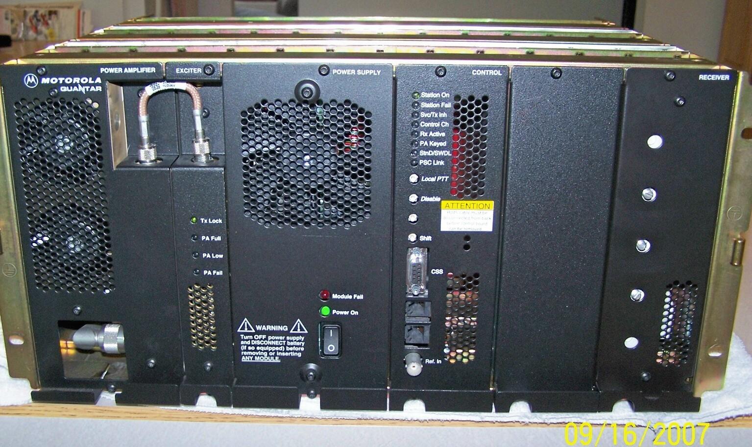
My station is a Motorola Quantar, 125-watt, continuous duty, VHF, low range,
132-154 MHz with the optional high-stability oscillator (HSO).
Why I purchased a Quantar and not a Ham repeater:
A local health-care system was evaluating use of ham radio for backup communications.
I had a chance to provide them with a loaner during the evaluation. However, since the
site also hosts multiple ambulance, fire, police, and other government systems,
interference or interaction would not be tolerated at any level.
A previous user on the site was removed due to interference. Since the site has N+1
power, data, and decent height, I was designing a system that would prove well-behaved
and (hopefully) be allowed to stay in place once the trial was over. It does not hurt
that the Quantar station is known as a system of choice for public safety communications.
One thing that sets the Quantar apart from the MSF and MSR stations is that
schematics are not readily available. Modules or FRU (Field Replaceable Units) are
swapped in the field. This does make it a bit difficult to work on.
Equipment Description:
Near identical unit to my R1 Quantar station. My station also has the X873AA ultra
high stability oscillator (UHSO). This model is officially known as a T5365A.
Where To Begin:
The quickest, most non-invasive method of identifying the basic band of a Quantar
station is to look at the receiver module on the right side of the card cage. A
700 / 800 / 900 MHz receiver will have no holes.
A UHF receiver will have 5 holes, but only three will have tuning slugs visible.
A VHF receiver will have five holes, with 5 tuning slugs visible.
If the station is in the desired band, the next step is to look at the rear of the
unit and read the part number label on the power amplifier module. It is usually
visible without removing the module.
There are two different numbers you may encounter on a module – the
OEM (Original Equipment Manufacturer) modules used during assembly at the factory
and if any modules have been replaced, FRU (Field Replaceable Units). If this is the
case, you will see different part numbers, typically with "LN" in the second and third
position.
The FRU and OEM units are the same components – one is a repair part,
the other is a factory-installed module.
All VHF Range 2 (150-174 MHz) equipment will tune and operate down
to approximately 146 MHz.
Power Amplifier Modules:
| OEM | FRU | Power | Frequency | Range |
| TLD3110 |
TLN3255 |
25w |
132-174 |
R1/R2 |
| TLD3101 |
TLN3379 |
125w |
132-154 |
R1 |
| TLD3202 |
TLN3254 |
125w |
150-174 |
R2 |
| TLE2731 | TLN3443 |
25w | 403-433 | R1 |
| TLE2732 | N/A |
25w | 440-470 | R2 |
| CTX1146 | DLN1216 |
110w | 380-433 | R0 |
| TTE2061 | N/A |
110w | 403-433 | R1 |
| TTE2062 |
TLN3446 |
110w |
440-470 |
R2 |
| TTE2063 | N/A |
110w | 470-490 | R3 |
| TTE2064 | TLN3450 |
110w | 490-520 | R4 |
| TLF1940 | TLN3441 |
20w | 800 | N/A |
| TLF1930 | TLN3442 |
100w | 800 | N/A |
| TLF1800 | TLN3299 |
100w | 900 | N/A |
If the number on the PA (power amplifier) is highlighted in red, the next step is to
remove the exciter to verify that it has the correct part number for the station. However,
on the exciter and receiver modules, the manual references a third part number (CLx) in
the "Factory Option Matrix". At least one of these, CLD1260 crosses to the TLN3251 in
MOL. However most do not cross in MOL.
Any of the three part number formats could possibly be found on a Quantar exciter
module. Most importantly, they all refer to the same component.
Exciter Modules:
| OEM | FRU | CLD | Frequency | Range |
| TLD9831 |
TLN3252 |
CLD1270 |
132-154 |
R1 |
| TLD9832 |
TLN3253 |
CLD1280 |
150-174 |
R2 |
| CLX4000 | DLN1214 |
CLX1000 | 380-433 | R0 |
| TLE5971 | TLN3305 |
CLE1230 | 403-433 | R1 |
| TLE5972 |
TLN3306 |
CLE1240 |
440-470 |
R2 |
| TLE5973 | TLN3375 |
CLE1210 | 470-490 | R3 |
| TLE5974 | TLN3376 |
CLE1220 | 490-520 | R4 |
| TLF6920 | TLN3307 |
CLF1510 | 800 | N/A |
| TLF6930 | TLN3308 |
CLF1520 | 900 | N/A |
Receiver Modules:
Each receiver module is made up of the receiver itself and the preselector. The same
part number identification system as the exciter modules applies.
| OEM | FRU | CLD | Preselector | Frequency | Range |
| TRD6361 |
TLN3250 |
CLD1250 |
TFD6511 |
132-154 |
R1 |
| TRD6362 | TLN3251 |
CLD1260 | TFR6512 |
150-174 | R2 |
| CRX4022 | DLN1215 |
CRX1027 | CRX4001 |
380-433 | R0 |
| TRE6281 | TLN3313 |
CLE1190 | TLE5991 |
403-433 | R1 |
| TRE6282 |
TLN3314 |
CLE1200 |
TLE5992 |
440-470 |
R2 |
| TRE6283 | TLN3373 |
CLE1210 | TLE5993 |
470-490 | R3 |
| TRE6284 | TLN3374 |
CLE1220 | TLE5993 |
490-520 | R4 |
| TRF6551 | TLN3315 |
CLF1530 | N/A |
800 | N/A |
| TRF6552 | TLN3316 |
CLF1540 | N/A |
900 | N/A |
Module Removal:
CAUTION: Make sure both the AC and DC (if so equipped) power is disconnected from
the station before removing or inserting any modules. An ESD strap is recommended as
well.
Each module is held in place in the card cage with two T15 Metric Torx screws. On the
100-watt stations, a short coaxial jumper feeds the power amplifier module from the
exciter in the adjacent position in the card cage. This needs to be removed prior to
removing the exciter or power amplifier. All modules unplug from the backplane as you
slide them forward.
Quantar Bonus Items:
The Quantar station may be equipped with several items that make it more attractive
for amateur use:
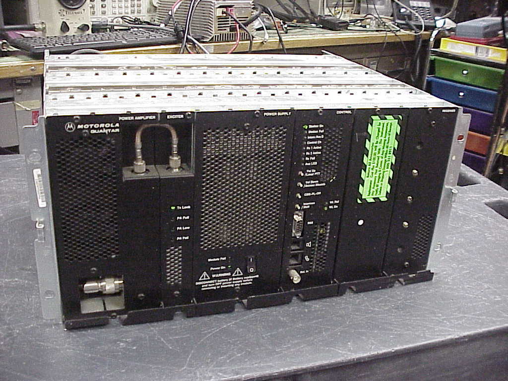
- The CPN1042A power supplies manufactured by Onan have a track record of the filter
capacitors failing catastrophically. The CPN1042A power supply has vent holes covering
about 80% of the front panel. The current production CPN1048A power supply has vent holes
over 40% of the front panel and the cooling fan is visible from the front of the card cage.
- X873AA ultra high stability oscillator (UHSO). It is always positioned between the
control module and receiver module. If the station does not have the high stability option,
there will be a blank module in the card cage.
- Battery Revert - if the station has battery revert, the DC cord is usually fitted. If
the cord is not in place, there will be a card edge connector visible at connector 25 on
the rear panel. No connector means no battery revert option. Note: there may be a blank
cover (P/N 1582596Y01) over connector 25.
- 4 wire vs. 8 wire control - Josh Heide K6ZRX has an article on adding extra control
functions that may be found by clicking here.
Station Programming:
Obviously a VHF Quantar station (132-174 MHz will program on amateur
frequencies with the stock Radio Service Software (RSS). Please do not ask
me for a copy. The local two-way radio shop programmed my Quantar for a fee.
Reference Material:
- Quantar instruction manual (6881095E05-O)
- Quantar Radio Service Software User's Guide (6881096E10)
- Standards and Guidelines for Communications Sites (6881089E50)
Handy Part Numbers for Accessories:
- Quantar DC Power Cable (TRN5155A)
- Quantar center mount brackets (TTN5028A)
- Quantar local Microphone (HMN1001)
- Quantar local Speaker (HSN1000)
- Quantar RSS (RVN5002)
- Quantar Programming Cable (3080369E31)
Test Equipment Used:
- DA-458/URM Dummy load (Bird 6733)
- Fluke 189 digital multi-meter, 4.5 digit display
- Fluke 199C portable oscilloscope, 200 MHz bandwidth
- Telewave 44A wattmeter, 1 GHz, 500-watt
Update from the page maintainer, Mike WA6ILQ:
1) If you look closely at the receiver in the photo at the top of this page you will see that the receiver has three slugs – it is a UHF receiver.
2) Here is a photo of a silver chassis Quantar with the Onan power supply (the one to avoid).
3) The "silver" chassis are the older Quantars, the "gold" chassis shown in the photo at the top of this page are the later stations.
People tend to prefer the gold chassis as they probably will have a later blackplane and probably later modules.
However the used market is such that the presence of newer modules in a used chassis is not assured.
4) Most Quantars have a BNC jack for an external 5 or 10 MHz reference. This can replace the UHSO and is most commonly used on 700 / 800 / 900 MHz trunking stations (where a number of Quantars are side-by-side at a site), and to a lesser extent on UHF stations to keep them precisely on frequency.
4) Part numbers:
HMN1001 - note that this is a mobile microphone with a 6-pin(!) plug, NOT an 8-pin RJ-45 style. It is also used on the MSF5000 stations.
HSN1000 - this is an amplified speaker originally made for the MT1000 mobile handheld charger and used on several generations of mobile handheld chargers. It can frequently be found on ebay, or you can use 1/2 of a set of amplified PC speakers. You may have to make a a cable for it, the audio at the speaker jack is line / earphone / handset level. There is 12 volts on that jack to power the external speaker.
The TRN7738A is a kit of the External Speaker Hardware bracket and cable. The diagram of that cable is on the MTR2000 page at this web site.
A TMN6124 or TMN6164 Handset can also be used with a Quantar and just plugs right in. They show up on ebay occasionally.
The 3080369E31 Quantar programming cable was replaced by 3080369E32. However you can make this cable, it is just a 9-pin male on the Quantar end and a 9-pin female on the computer end, and a length of 3-conductor cable in the middle. The connection diagram is on the Quantar index page (the previous page).
|
Acknowledgements:
Doug (AKA Batdude) for his excellent article on
BATLABS, which provided a basis for my work.
Larry (AKA Astromodat) and XMO for their identification of the infamous Quantar
exploding power supplies.
The staff of www.repeater-builder.com
Contact Information:
The author can be contacted at: his-callsign [ at ] arrl [ dot ] net.
The page maintainer, Mike Morris WA6ILQ, can be contacted here.
Back to the top of the page
Up one level (Motorola index)
Back to Home
This page originally posted on Wednesday 19-Mar-2009
Article text, photos, artistic layout, and hand-coded HTML © Copyright 2009 by Martin A Flynn W2RWJ.
This web page, this web site, the information presented in and on its pages and
in these modifications and conversions is © Copyrighted 1995 and (date of
last update) by Kevin Custer W3KKC and multiple originating authors. All Rights
Reserved, including that of paper and web publication elsewhere.
