Motorola index
Back to Home
R100 (and MCR100)
UHF Repeater (RT)
Station Overview
By Robert W. Meister WA1MIK

|
R100 index Motorola index Back to Home |
Motorola® Radius® R100 (and MCR100) UHF Repeater (RT) Station Overview By Robert W. Meister WA1MIK |
|
This article provides an overview of the R100 and MCR100 UHF repeaters. All of the information came from physical examination of the station and running the programming software, as well as the R100 Instruction (and service) Manual, p/n 6881078E15 and the MCR100 Instruction (and service) Manual, p/n 6881071E50.
The following specific questions and topics were originally found in the "Articles We'd Like To See" page. They'll be covered in this article. Additional service-related items have also been added.
| Question or Topic | Answer |
|---|---|
| Moving a Motorola R100 repeater from commercial to amateur frequencies, including RSS screen shots and interfacing it to an external repeater controller. | Hex-edit the software, program and tune the radios. Read further for interfacing suggestions. |
| What manual part numbers are the correct ones to order? | Manuals are No Longer Available and cannot be ordered. PDF files are posted on Repeater-Builder. |
| What knowledge would someone familiar with the R100 radios wish they had before they got into them (like the fact that the R100 can do either PL or DPL, but not both, and changing from one to the other requires replacing the controller board), and enough information that listings on eBay make sense? | The model number is about all you can go by, along with a photo of the insides to make sure the unit is physically complete. Parts to convert PL to DPL or vice versa are No Longer Available. |
| An interfacing article would be very welcome: how to hook up an external controller, how to get muted receiver audio out of the radio, along with COR and PL decode, and how to insert transmit audio into it, along with PTT and how to control the transmitter PL encoder. | Read further for details and interfacing suggestions. |
| The repeater is stuck transmitting all the time. | C894 in the RPTR DROP-OUT DELAY circuit is shorted. |
| Insufficient A+ voltage and can't adjust A+ voltage. | One or more diodes bad in the power supply bridge rectifier or the main filter cap is bad. |
General Overview and Features:
As far as anyone can tell, the R100 and MCR100 are identical stations. The MCR100 was manufactured for the European market and there are more options listed in the MCR100 manual. All parts are interchangeable and have identical specifications. Throughout this write-up, the R100 product name will be used to refer to either or both stations.
The radio modules used in these repeaters are based on the MC Micro product line, which was probably a predecessor to the MaxTrac/Radius mobile radios. There is evidence in the manuals that these stations were available for the VHF mid-band (72-76 MHz), VHF high-band (136-174 MHz) and UHF (403-433 and 450-470 MHz) bands. European models covered 66-88, 136-162, 146-174, 403- 433, 422-450, 438-470 MHz ranges. Also, the receiver radio could be used by itself as a full transceiver in base-station applications. The transmitter radio in my station had two coax cables plugged into it: one for the transmitter RF output and one for the receiver RF input (from the antenna switch in the power amplifier). I suspect the receiver jack on the RF board is just there to hold the cable.
The European market calls this an MC Compact station. It was available in 68-88, 136-174, 174-225, and 403-470 MHz versions, with power ranges of 1-6, 1-10, or 25 watts.
The R100 is a full-duplex, intermittent-duty, wall-mounted UHF repeater station composed of a receiver, transmitter, power supply, and control board. A duplexer is not contained in the package; one must be provided externally. They come in several variations or configurations:
In most cases, it is NOT possible to alter this configuration without replacing major assemblies. For example, the repeater control board won't have the parts installed on it for control tone decoding if it wasn't originally configured or ordered that way. Similarly you would need to replace the RF Power Amplifier to get more output power. Worst, however, is that the transmitter and receiver are built to do either Private-Line (PL) or Digital Private-Line (DPL), but not both. You can't change from one to the other without replacing the microprocessor (No Longer Available) and a few other parts on the radio's control board; these parts are documented in the manual. The encoding (in the transmitter) and decoding (in the receiver) is performed by the microprocessor on the respective unit's control board.
Both the receiver and transmitter are capable of one single operating frequency (or channel), although there is evidence that two channels were possible in some configurations. The transmitter and PA are designed for wide-band coverage; the only item that needs tuning after being reprogrammed is the VCO. Deviation must be checked or adjusted after programming. The transmit RF board has a 2ppm reference oscillator; the receiver has a 5ppm temperature-compensated crystal oscillator. The receiver is quite narrow and selective; there are nine tuning coils to adjust plus the VCO when the frequency is reprogrammed. For comparison, the MaxTrac/Radius radios are wide-band and no field tuning is required; the alignment procedure and 16 tuning points deal with the wide frequency range these radios cover.
A repeater "hang" timer is configurable via resistor values and the transmitter time-out timer can be enabled and set to 0, 3, or 15 minutes via software. There is NO CW ID facility. Repeater Enable (set-up) and Disable (knock-down) as well as PL Disable commands are available with tone remote control. The stations were commonly interfaced to telephone phone patches or desk sets. There are markings indicating that the control board and receiver radio could be configured as a single radio base station, which is a totally different product.
The receiver and transmitter are almost clones of Radius/MaxTrac radios. They're both made for 5 kHz deviation channels (25 kHz channel spacing); the programming software says you can enter frequencies that are divisible by 5 or 6.25 kHz, implying frequencies on 12.5 or 25 kHz increments (probably depending on the band). The circuitry is nearly identical and anyone familiar with those radios can easily work on the R100. The RF and command boards used by the receiver and transmitter are not interchangeable since unnecessary parts have been left off depending on the intended use. Here's a photo of the two radios; the receiver is on the left (RF board facing up, missing a VCO shield and an overall board shield), the transmitter is on the right (command board facing up). Each unit is composed of an RF board and a command board:

The black heat sink at the right end of the station helps cool both the power supply and the RF Power Amplifier. The PA has a temperature-sensing thermistor and an output power sensor to assist the station in maintaining desired output power under all conditions. There is no fan, power switch, or other external indicator. There are two small LEDs on the power supply regulator board; the green one lights up when AC power is running the station; the red one lights up when the external (battery backup) supply is running the station. Here's a view of the power supply and part of the RF power amplifier, looking towards the heat sink:
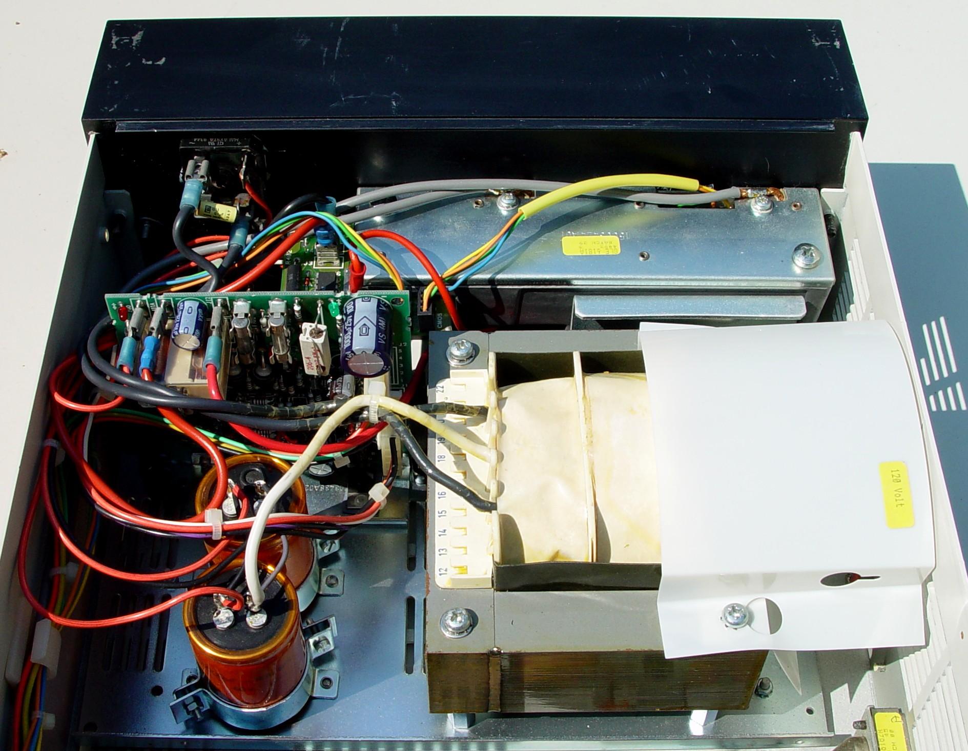
I found this photo on the web. It shows a non-battery-charging power supply. One obvious difference is that it has only one large filter capacitor instead of two, and it's mounted to the regulator board rather than the chassis. This power supply version is not documented in the R100 manuals I've encountered, however I also found this same supply in a Q2903B station, so perhaps the "B" version means it has a revised power supply.
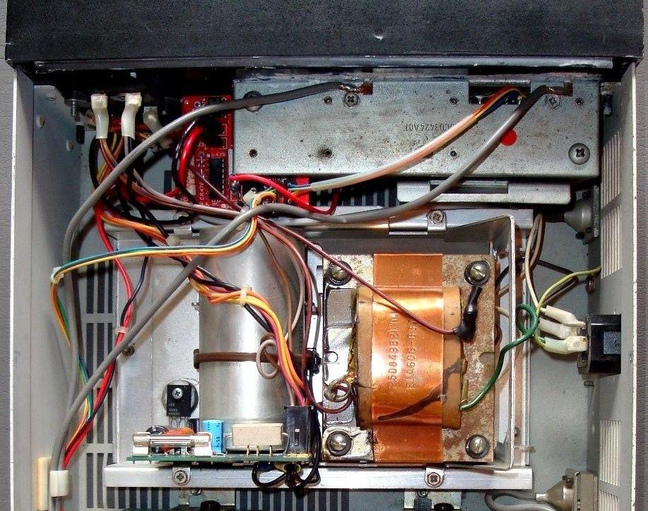
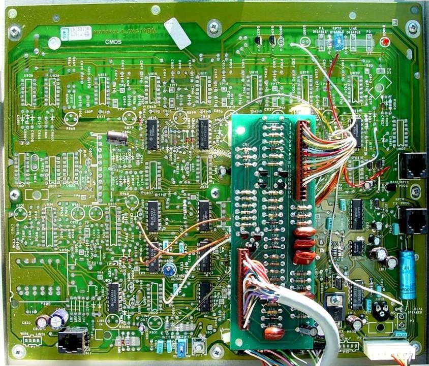
The station is designed to be wall-mounted. The front cover lock uses the standard Motorola 2135 mobile key, which can be removed in both the locked and unlocked positions. The main control board, which also handles remote control tones, is mounted to the hinged front cover. All other modules are mounted to the chassis. My station was not equipped for remote control tones, but it does operate as a stand-alone repeater. Here's a photo of the control board:
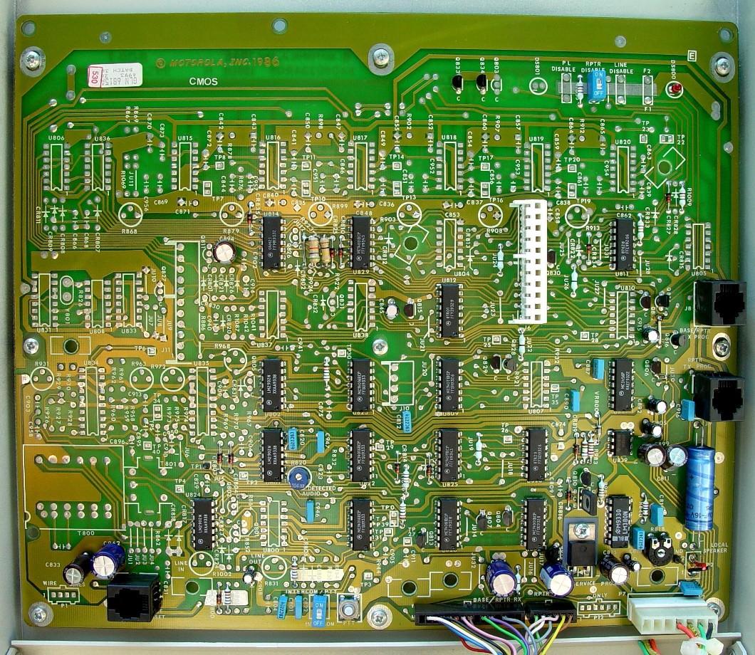
Here's a fully populated control board without the DB25 Auxiliary Jack and its interface board and wiring, courtesy of Javier EB1WB.
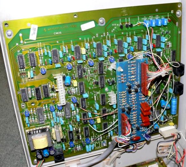
Here's another identical model number radio that has the DB25 Auxiliary Jack and the interface board it plugs into, allowing for some external control console. This board has wires that are soldered to several dozen specific points on the control board. The big cable in the middle goes to the DB25 jack.
For comparison, here's a photo of a fully populated (tone remote) control board (picture found on the web):
Jan DD8OA sent in a photo of a German MC-Compact base station's fully populated control board. Note that it has a second board over much of the left half.

Battery backup and trickle charging seems to be a standard feature but some supplies don't have these components. There are provisions inside for two-frequency operation, however this does not seem to be supported by the programming software and the various modules.
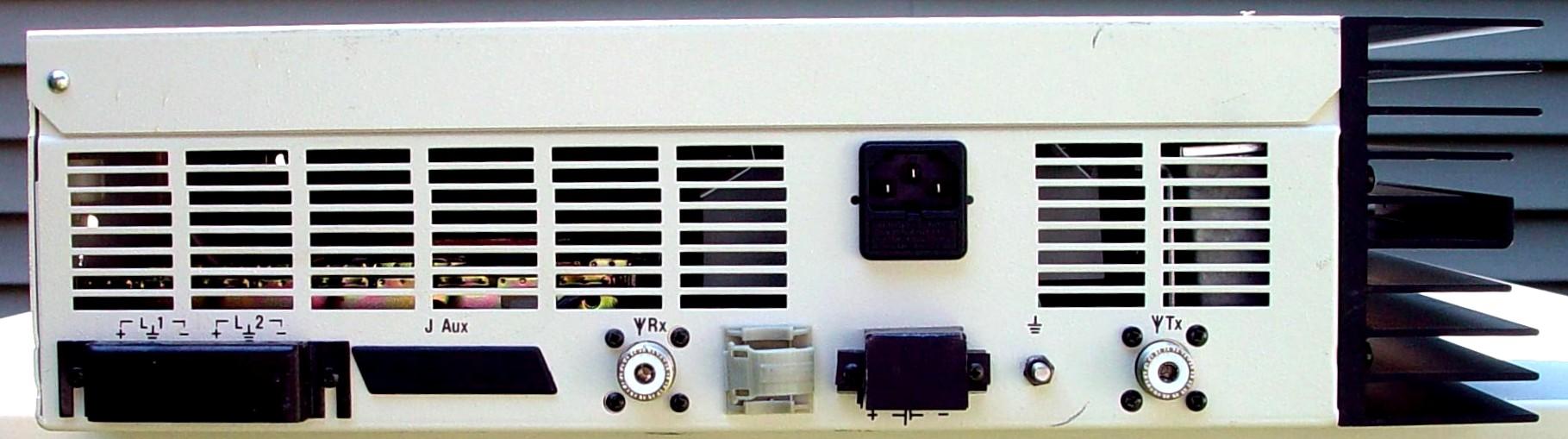
Here's a view of the bottom of the station showing all the connectors. They are, from left to right: wire-line terminals (covered but not installed), Auxiliary Jack (DB25-style, not installed), receiver input jack (UHF), a plastic cable clamp, AC input (standard IEC connector), DC input screw terminals (covered), ground stud, and transmitter output jack (UHF):
Model Number Information and Specifications:
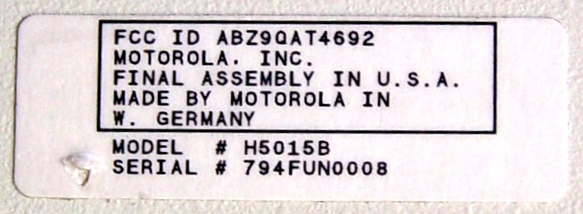
The model numbering is rather odd. My station has the "H" number on the label, which was found on the outside left (hinged) end of the cabinet opposite the heat sink:
The UHF R100 repeaters come in four basic styles (this information came right out of the Instruction manual) and you can't tell which one you have by a casual inspection inside the box:
| R100 Model | MCR100 Model | Alternate Model | Squelch | Watts |
|---|---|---|---|---|
| H5015A | Q2903A | G1040A | PL | 25 |
| H5016A | Q2904A | G1040A-SP500 | DPL | 25 |
| H5017A | Q2931A | G1046A | PL | 2-10 |
| H5018A | Q2932A | G1046A-SP500 | DPL | 2-10 |
Note that the DPL models are shown as "SP" variations. Also note that the revision letter, shown as "A" in these tables, could be a different letter. Just to confuse you, another model table lists additional alternate model numbers:
| Alternate Model | Control | Squelch | Watts |
|---|---|---|---|
| G1039A | Tone | PL | 25 |
| G1039A-SP500 | Tone | DPL | 25 |
| G1040A | Repeat | PL | 25 |
| G1040A-SP500 | Repeat | DPL | 25 |
| G1045A | Tone | PL | 2-10 |
| G1045A-SP500 | Tone | DPL | 2-10 |
| G1046A | Repeat | PL | 2-10 |
| G1046A-SP500 | Repeat | DPL | 2-10 |
Almost all of the circuit board and major assemblies have "GLN" prefixes on them (the MaxTrac/Radius modules have "HLN" prefixes).
The performance specifications for the entire repeater state 450-470 MHz operation, however the PA and RF board schematics all show a 438-470 MHz range; a 403-433 MHz range seems to have been an option at one time.
This is a low-power industrial (LPI) repeater. As such, the duty cycle is rather limited. Normal intermittent use is 25% transmitting and 75% receiving (or idle) with 30 minutes of continuous transmit time available at 25 watts. The output power will be reduced if necessary - when the unit gets hot - to insure safe operation. There is no cooling fan in the R100; if you intend to use this for amateur repeater service, one or two fans blowing on the heat sink are mandatory and an additional fan inside would be helpful.
The AC input requirements (probably for a fully-loaded and accessorized station) are surprisingly high: 36 watts on standby, 150 watts transmit (2-10W RF output), or 360 watts transmit (25W RF output). That's pretty inefficient. When operating on nominal 12VDC, things are a lot better: 0.75A (9 watts) on standby, 3.9A (46 watts) transmit (2-10W RF output), or 8.75A (105 watts) transmit (25W RF output). At least that's closer to 25% efficiency. After tuning my station on a 456/451 MHz pair at 25 watts, I measured the following AC parameters using a P4400 Kill-a-Watt meter: AC Volts, AC Amps, Watts, Volt-Amps, Power Factor, and Efficiency. I also measured the draw when powered by an Astron RS35: DC Volts, DC Amps, Volt-Amps, and Efficiency:
| Mode | ACV | ACA | W | VA | PF | Eff | DCV | DCA | VA | Eff |
|---|---|---|---|---|---|---|---|---|---|---|
| Stdby | 118.9 | 0.41 | 20 | 49 | 0.41 | --- | 14.0 | 0.5 | 7 | --- |
| Trans | 117.8 | 2.07 | 192 | 242 | 0.78 | 13 | 14.0 | 7.0 | 98 | 25 |
RF performance is just about the same as a MaxTrac or Radius mobile radio. The receiver is not wide-band; it does require tuning to your frequency. As such, it is a lot tighter than a MaxTrac or Radius and will reject a significant amount of off-channel interference. After aligning my unit, it opened squelch (with a PL-encoded signal) at -127dBm (0.1uV) and all the crackles were gone at -115dBm (0.35uV). 20dB quieting was obtained around -118dBm (0.3uV).
The transmitter was initially producing 35 watts; I turned it down to 25 watts per the alignment procedure. I was able to adjust the carrier frequency to within 50 Hz.
Programming Cable:
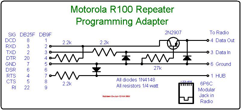
You can still buy after-market programming cables for these stations. Most are so-called RIB-less designs, where the level shifting is done within the cable itself and no separate RIB is required. The cable runs directly from the station to your computer. Some are terminated with DB25, others with DE-9, and an adapter between the two may or may not be provided. These radios use separate TX and RX Data lines for programming; the RIB operates with a single Data line that carries both TX and RX signals and the signal is split for the computer. This significant difference is why a RIB can't be used and no RIB-based cables exist. You must buy a cable made for the R100 or build one yourself. Here's one schematic of such a cable:
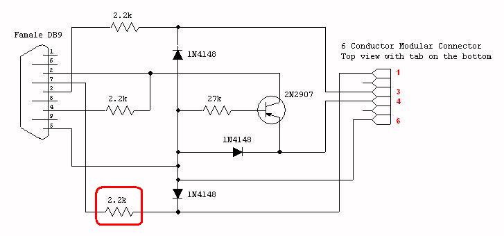
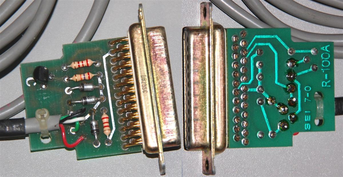
Bob VE3DJ opened his official Motorola programming adapter cable, p/n 0180358A52 and sent pictures to me. Here's an inside view. The circuit matches the schematic diagram above, except that the real cable had a DB25F while the one above converted it to a DE-9F, and the 2.2k resistor outlined in red:
The R100 schematics show the programming connector pin numbers oriented one way, while the R100 circuit board X-ray view shows them oriented the other way. Since a picture is worth a thousand words, here's a photo of the radio-end of a programming cable (while it's not obvious, all six wires ARE present):
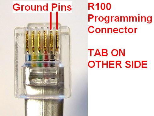
The pin and signal descriptions for these connectors is shown below. Other Motorola documents seem to agree with the schematic pin numbering convention, where Pin 1 is on the left and Pin 6 is on the right (when looking into the jack with the tab down). They also have had this same numbering swap in other manuals of products manufactured and documented in other countries (i.e. the Motorola DeskTrac).
| Signal Name at the R100 |
Schematic Pin # |
X-Ray View Pin # |
|---|---|---|
| HUB | 1 | 6 |
| Not Used | 2 | 5 |
| Data In | 3 | 4 |
| Data Out | 4 | 3 |
| Mic Lo | 5 | 2 |
| Ground | 6 | 1 |
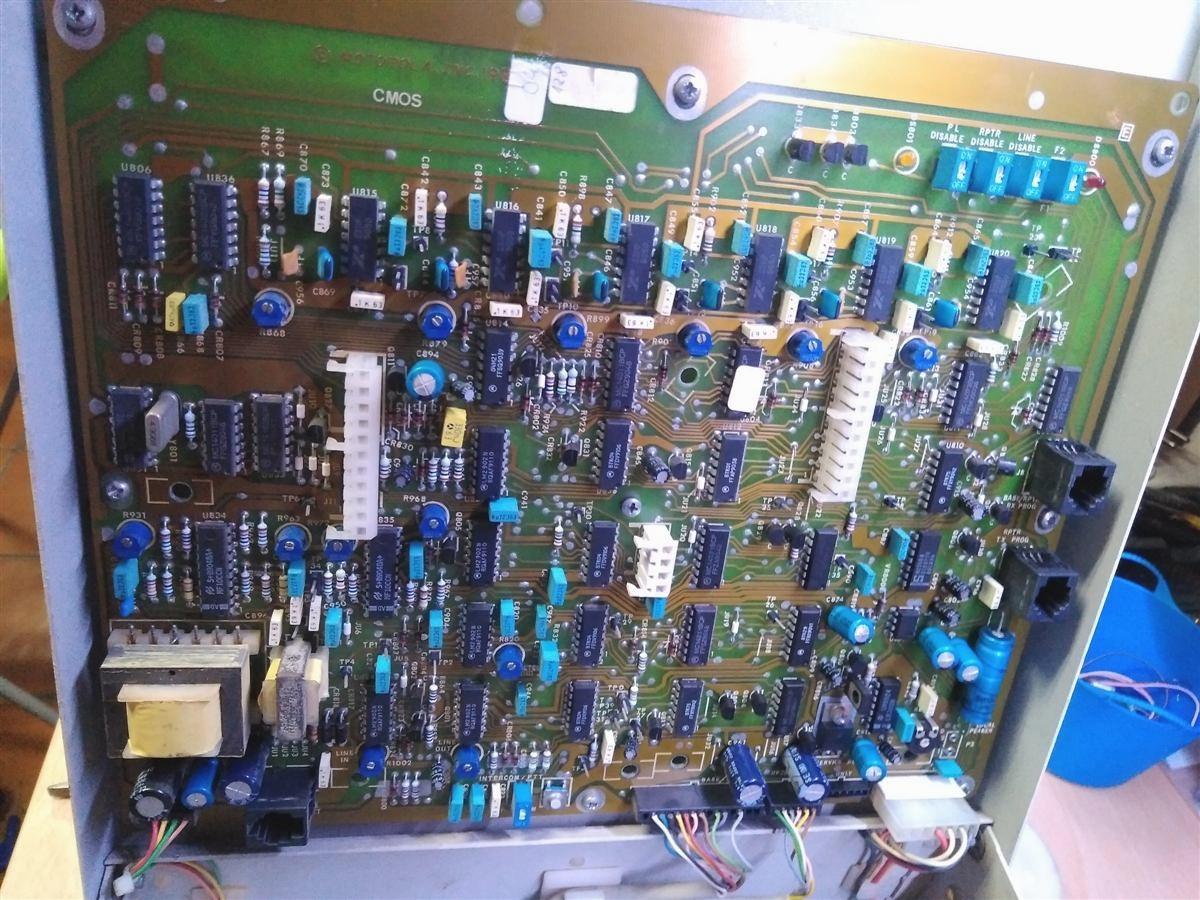
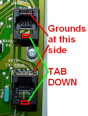
There are two identical programming jacks in the R100: one for the receiver, one for the transmitter. You must program each radio separately and move the programming cable accordingly. They're along the top edge of the control board mounted inside the front cover, shown here:
I made my own DE-9F programming cable for a few bucks and an hour's time, following the schematic above. I had to be a bit creative about parts positioning and orientation, but I took my time, drew a pictorial diagram, stuffed everything into the plastic housing, and checked for shorts. I was rewarded by being able to successfully read and write the code plugs of both radios several times. The parts values aren't terribly critical.
I discovered that there's a design defect in the programming cable. The signal that goes from the DE-9 connector pin 7 is clamped with a diode to prevent it from going below ground. This is the RTS output from the computer and it is a standard RS-232 signal that really wants to go between -6V and +6V. The diode prevents it from going negative. There really should be a protective resistor between the DE-9 pin 7 and the rest of the circuitry to limit the current when RTS is negative. A 2.2k resistor is recommended and has been added to the revised schematic above and below.
Amateur Frequency Programming and Conversion:
The Radio Service Software for the R100 is a very small and simple COM program that runs under MS-DOS (definitely pre-Windows anything). It limits frequency entry to the legal range for the radio: 450-470 MHz. These values can be easily changed with any hex editor. The table below shows the data values in red cells you can modify to expand the range to 438-474 MHz. Note that the word values are shown with the least significant byte first (Intel order) and they're at odd (byte, not word) addresses.
| Hex Address | Original Values | New Values | ||||||
|---|---|---|---|---|---|---|---|---|
| Byte | Byte | Word | Decimal | Byte | Byte | Word | Decimal | |
| 3A43 | C2 | 01 | C201 | 450 | B6 | 01 | B601 | 438 |
| 3A45 | D6 | 01 | D601 | 470 | DA | 01 | DA01 | 474 |
The receiver, transmitter, and power amplifier cover 438-474 MHz, so all you need to do to bring the unit into the amateur band is program it and tune it up.
Running the Programming Software:
The Radius R100 repeater is programmed with Radio Service Software, product identification HVN9177 or HVN9178 (depending on the media size). The version that seems to be commonly available is:
   RADIUS R100 FIELD PROGRAMMER  V1.9
 (c) COPYRIGHT MOTOROLA INC. 1985, 1986

Standard Version          Date: 02/17/88
Its operation is NOT intuitive. Read the Programming Notes PDF file several times, noting all the little things it tells you to do (like keyboard settings). While the program would start (and apparently run) on a fast computer, it would not read data from the station. I ended up running it on a 486-25 monochrome computer. I'm sure this is due to speed-dependent timing loops inherent in first generation software written in the late 1980s. These timing issues affected a lot of Motorola programming software of that era; this was eventually fixed in later versions for products that were available in the 1990s. With 24C01 EEPROMs installed, my station seems to read and write just fine with a Pentium 100 MHz laptop computer, but others have had issues with stock stations.
It takes about 10 seconds to read a code plug from either radio. It takes almost twice as long to write the data back out. Certainly it's a lot faster than some other products, but considering how little data it really deals with, even this is a long time. It turns out that RSS is reading twice as much data as is actually present in the station, but when it writes the data back, it also reads it back after the microprocessor writes it to the EEPROM to verify the integrity of the data.
You can only change the receiver and transmitter frequencies and squelch codes, one per radio, (these are single-channel repeaters) and the transmitter timeout timer. The repeater hang-timer is set with resistors and one jumper on the control board; this and all the other jumper settings are documented in the Instruction manual. The software lets you read, edit, and write the radio's data, and specify which serial port is connected to the station (COM1 or COM2 only). You can print the data to a printer attached to LPT1. You can't read or write a code plug to or from a disk. There are so few parameters that it really isn't necessary. The program identifies the radio (receiver or transmitter) when the code plug data is read. It's up to the user to enter the appropriate data. While you can choose PL or DPL for either radio, you must make sure that your choice matches what the radios are actually capable of. You can't change it with the software.
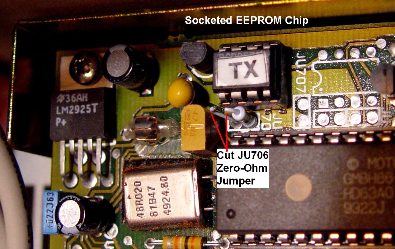
The code plug data is held within a small 8-pin socketed serial EEPROM on the command boards. If the data in this IC gets corrupted or the IC goes bad, you're really up a creek. There's no way to initialize a blank IC with the available programming software. You'd need another good EEPROM to read first, and then try to write it to a blank one in the radio. Another alternative is to use an EEPROM burner and copy a good one. If you have access to a burner that can read and write these devices, it would be wise to read and save images of the two EEPROMs in the station, just in case you run into this situation later. Of course, the VHF and UHF data is completely different.
The serial EEPROM on my transmit command board is a Microchip PCD8572. This chip is no longer manufactured nor available. It is supposed to be compatible with the 85C72 chip, also rather old. The currently available 24C01 chip seems like a good match but Microchip would not suggest a replacement. I have used 24C01 chips successfully.
There's a small zero-ohm jumper next to the EEPROM labeled JU706. Each board has one. They've been cut on my station. I've read that this jumper needs to be intact to allow programming of the chip, but mine programmed just fine as-is. Perhaps this is used when the station is first manufactured (initial blank programming). Here's a photo of that jumper, although you can't see the actual numbering next to it because it's hidden by the microprocessor IC socket.
Expanded Software Capabilities:
There is another (lab) version of the software (also V1.9 dated 2/17/88) floating around that gives you additional menu options. You can change four locations in the R100.COM program to make these available. As always, create a backup copy in case something goes wrong. Use a hex editor of your choice and change the following four locations. All address and data values are hexadecimal.
| ADDR | FROM | TO |
|---|---|---|
| A6F1 | 75 | 74 |
| A8F9 | 75 | 74 |
| A948 | 75 | 74 |
| AAA8 | 75 | 74 |
After modifying the file, it will now display the following initial screen. As always take great care with anything you do when using this program. You can render the code plug completely invalid and have no way to repair it.
   RADIUS R100 FIELD PROGRAMMER  V1.9
 (c) COPYRIGHT MOTOROLA INC. 1985, 1986

Master Version            Date: 02/17/88

For MOTOROLA Internal Use Only
Service Aids on the Control Board:
A repeater enable/disable slide switch - with indicator LED - can be used to take the station out of service. You could wire something across this switch if you wanted to disable the repeater externally.
A momentary push-button can activate PTT - without passing audio - for testing.
A handset (such as the TMN6146A, documented on the MSF and PURC page) can be plugged into yet another RJ12 jack on the control board. This is wired exactly the same as for the control jack on the front of an MSF5000 station. It lets you talk and listen to the transmitter, receiver, and wire-line remote control audio.
There are provisions for an external four-ohm loudspeaker; there's a volume control mounted on the board. My station had a pair of wires soldered to the board at this position, but the manual says a connector is present. I did find two small pin-jacks that could have wires stuck into them; in my station they were filled with solder. I've since cleaned them out.
There are provisions for disabling receive PL decode (for tuning / monitoring purposes only; the repeater always requires receive PL). My station did not have the components installed for that feature. I've installed the parts necessary to activate that function. See the companion PL Disable article for photos and a step-by-step procedure.
Things I Found During Alignment:
When I received this radio, I assumed it was in working condition. Poor assumption. I read the two code plugs and wrote down the frequencies (both in the 455 MHz range) and PL codes. It would neither receive nor transmit as I got it. The radio needed a complete realignment; the complete procedure is covered in a few pages in the Instruction manual. After spending 10 minutes tweaking it up, it worked fine.
The receiver is easiest to adjust because the RF board is facing you and all the adjustments are readily accessible. A DC voltmeter is used to adjust the VCO and injection tuning. A wideband AC voltmeter is used to adjust the front end, although you could just do it by ear or with an AC voltmeter on the speaker terminals and adjust for maximum quieting and least crackles. Tuning was straightforward and the receiver worked fine. The one difficulty I had was that there was no PL DISABLE switch on the control board in my station, so I had to modulate the tuning signal with PL to hear anything on the speaker. I tried shorting out the two pads where the switch would have been installed and that DID disable the PL, but only for the monitor speaker. The repeater still requires PL in order to repeat a signal (if the receiver is programmed that way).
The transmitter would not key up using the manual PTT button on the control board. As it turns out, this was just due to the VCO alignment. If the transmit synthesizer does not lock, the unit will not transmit or even attempt to transmit. The VCO adjustment is done on the transmit RF board, which is mounted on the underside of the transmit assembly. One 7/32-inch nut holds it in place. Loosen the nut, slide the assembly towards the power supply, lift the other end off the stud mounted on the left side of the cabinet, and swing the assembly around to get to the RF board underneath. The transmit RF board had a full pop-off shield (the one on the receiver was missing). The VCO area had a similar shield (similarly missing on the receiver). Removing these gave me access to the VCO, reference oscillator, and deviation pots.
I tried adjusting the transmit VCO but could not get the required 6VDC at the SL test point. THEN I discovered that the transmit VCO does not operate unless the unit is transmitting (this makes sense, of course, and the manual tells you to press the PTT button on the control board), so after twiddling the trimmer capacitor and the VCO coil unnecessarily, I pressed the PTT button and retuned both of them until I got 6VDC at the SL test point. The transmitter responded by putting out some serious RF power, nearly 40 watts. Good thing I had already attached my wattmeter and dummy load.
I then proceeded to adjust the RF output power. This is a rather convoluted procedure that I could not fully understand, so I just used my brain and did what works for the Spectra PA adjustments: I set the power to about 30 watts, adjusted the current limiting so it just started to reduce the output power, then backed off a tad, then reset the output power to 25 watts. I then set the power adjust pot fully clockwise and set the voltage limit pot for 30 watts, then reduced the power to 25 watts with the power adjust pot. I don't know why Motorola had to make the procedure in the manual so complex.
The transmit frequency adjustment is also done on the transmit RF board. Of course I had already reinstalled that assembly, so I had to pull it back out and tweak that pot. I got the frequency within 50 Hz at 456 MHz.
The station does repeat an incoming signal. It has been configured for zero hang-time and RF output ceases about 1/2 second after loss of incoming carrier (delay due to PL encode reverse-burst). I will eventually retune this station for amateur frequencies.
The power transformer and heat sink get warm and emit heat, even during my brief tuning session. The station was sitting on its back; if it was wall-mounted, there would be some convection cooling of the unit.
During testing, I measured the PL deviation at 650 Hz and the maximum deviation at just about 4.5 kHz. I have not actually adjusted the two deviation pots. It makes sense to program the transmitter for carrier squelch (i.e. NO PL) when you adjust the REF MOD deviation. The alignment section of the Instruction Manual does not mention this. Overall deviation needs to be set with PL present.
One pot on the control board (Detected Audio Level) controls the repeated audio level.
Interfacing to External Equipment:
Obviously if your station has the DB25 connector and the internal interface components, life will be simpler, assuming you can make do with the signals you have access to. However, since the internal control board does not provide a CW ID, you'll need at least that capability in an external controller. A Com-Spec ID-8 can be connected rather easily to JAux. The following information was provided by Dave N1OFJ:
Com-Spec ID-8 CWID Board To R100 Repeater JAux Interface
| ID-8 Signal | Wire Color | R100 Connection at JAux |
|---|---|---|
| Power: J1-1 | Red | Pin 3: A+ |
| Ground: J1-3 | Black | Pin 6: ground |
| Morse Audio Output: J1-9 | Violet | Pin 5: audio from phone patch |
| Inhibit Input: J1-7 | Blue | Pin 23, added to connector |
| Trigger Input: J1-8 | Orange | Pin 23, added to connector |
| PTT Output: J1-2 | Grey | Pin 4: PTT, also to JAux pin 25 |
| Grey | Pin 25, added to connector |
Notes:
If your R100 is capable of PL, and you want it to do DPL, or vice versa, you'll have to program the radios for carrier squelch and use an external encode/decode unit or a controller that has that capability built-in.
If you only need simple repeater functionality, you can get by with just these signals. Note that this is basically the same as interfacing to a pair of MaxTrac/Radius radios and the signal levels are almost identical.
It is certainly possible to wire up directly to the individual radios, either through their DA-15 connectors or to specific points on their command boards. You can peruse the control board schematic and probably find suitable places to attach a bunch of wires and make something work, however everything you need except COR Out can be found on the RJ12 Service Jack, J3. There is one unused pin that can be wired up to provide a COR Out signal, making a very clean interface job possible. Here are the specifics of the signals present on J3. Pin numbers are referenced to the schematic, NOT the circuit board layout.
| Pin# | Signal Name | DCV | Notes |
|---|---|---|---|
| 1 | Not Used / Spare | - - - | Can be wired for COR Output |
| 2 | Headset Audio OUT | - - - | Fixed level: 55mV/kHz at 400 Hz |
| 3 | Push-To-Talk IN | +12.7 | Active Low: draws 2.5mA |
| 4 | MIC HI | +9.6 | DC Bias present. 50-100mV/kHz |
| 5 | MIC LO (ground) | 0.0 | Audio Ground, tied to pin 6 |
| 6 | Logic Ground | 0.0 | Logic Ground, tied to pin 5 |
Note that there's a DC voltage on the MIC HI signal, used to power the preamp in most Motorola microphones. Most repeater controllers don't expect this, so use a 10uF 16V electrolytic capacitor in series with this line, positive end towards the R100.
COR signals can be found in several places on the control board; I've listed a few below and there are probably more. Use whichever one you want. Note that a lot of the logic on the control board swings from ground up to +13V, not +5V. Measure the signal before using it and use a diode for isolation if necessary. P4 comes directly from the receiver but the connector pins aren't easy to get to. I personally like signals that are active when low, so I'd recommend J6 pin 9 for a COR signal. Make sure your external controller can deal with the high voltage with no signal present.
| Signal Name | Location | With Signal | No Signal |
|---|---|---|---|
| Carrier Detect | P4, pin 11 | 0V | +13V |
| PL Detect | P4, pin 13 | +4V | 0V |
| CSQ+PL Detect | J6, pin 9 | 0V | +13V |
| CSQ+PL Detect | U826, pin 11 | +13V | 0V |
Run a wire from the selected pin to J3 pin 1; a feed-through pad near J3 lets you access this pin without removing the control board. Make a cable that plugs into J3 and exits the repeater via any way possible, such as by installing a DB25 into JAux (if empty) or by using spare pins on JAux (if present).
If you foresee the need to control PL Decode (on/off), you'd be best to send both of the Carrier Detect and PL Detect lines to your external controller and let it handle that for you.
Commercial Interfacing Suggestions:
Various Connect Systems (CS) and Zetron (Z) controllers and/or community tone panels have recommended interface information for the R100 using JAux. The table below summarizes the JAux pin usage. Pins 23-25 are unused on the stock R100 and must be wired by the user to various points inside the station. See the notes after the table for connection information. Also refer to the manufacturer's documentation.
| Signal Name | CS | Z | Notes |
|---|---|---|---|
| Ground | 14 | 14 | |
| A+ Out | 3 | 3 | |
| PTT In | 4 | 4 | Active low |
| TX Audio In | 5 | 5 | |
| COR Out | 24 | 12 | Active low |
| CTCSS Enc. In | 23 | 23 | DC Present |
| Discr. Audio Out | 25 | 25 | DC Present |
COR Out: Connect Systems recommends running a shielded wire from the receiver command/RF board interconnect pin 9 to JAux pin 24. This signal isn't pulled to ground very well, so it would be wise to isolate it with some additional circuitry. Zetron just makes use of the existing Phone Patch Audio Control (activity) signal on JAux pin 12 that goes low under various conditions, including a received carrier.
CTCSS Enc. In: Connect Systems recommends you remove C607 from the transmit command board and feed your PL tone into the hole where the positive side of C607 went. Zetron recommends feeding your PL tone to U601 pin 9 on the transmit command board. You can also locate the "PL" test point, next to the microprocessor, and feed PL there. Use a shielded wire and connect it to JAux pin 23. You will need to use a 10uF 16V capacitor in series as there's DC voltage present on either of these connection points and you do not want to upset this.
Discr. Audio Out: Connect Systems recommends you pick this signal up from the receiver command/RF board interconnect pin 10 and run it to JAux pin 25 using shielded wire. Note that this is raw, un-muted, unfiltered discriminator audio. Zetron recommends taking buffered, un-muted, unfiltered discriminator audio from U551 pin 4 on the receive command board and run it to JAux pin 25 using shielded wire. You will need to use a 10uF 16V capacitor in series as there's DC voltage present on either of these connection points and you do not want to upset this.
Test Equipment Utilized:
Agilent E4430B RF signal generator
HP 5285A frequency counter
Fluke 189 digital multimeter
HP 8901B modulation analyzer
Telewave 44A RF wattmeter
DB Products 50 watt dummy load
Acknowledgements and Credits:
Motorola, MaxTrac, Radius, R100, MC Micro, MC Compact, MCR100, PL, DPL, RSS, and a bunch of other terms are trademarks of Motorola, Inc.
Information about the Com-Spec ID-8 can be found at Communications Specialists, Inc. web site: www.com-spec.com.
The P4400 Kill-a-Watt is a trademark of P3 International Corporation.
Connect Systems and Zetron are trademarks of their respective companies.
Thanks go to Dave N1OFJ for coming up with the Com-Spec ID-8 wiring information.
Thanks also go to Bob VE3DJ for supplying photos of the R100 programming adapter.
All photos were taken by the author unless otherwise indicated.
Contact Information:
The author can be contacted at: his-callsign [ at ] comcast [ dot ] net.
Back to the top of the page
Up one level (R100 index)
Up two levels (Motorola index)
Back to Home
This page originally posted on Tuesday 21-Jul-2009
Article text, artistic layout, and hand-coded HTML © Copyright 2009 by Robert W. Meister WA1MIK.
This web page, this web site, the information presented in and on its pages and in these modifications and conversions is © Copyrighted 1995 and (date of last update) by Kevin Custer W3KKC and multiple originating authors. All Rights Reserved, including that of paper and web publication elsewhere.