Motorola index
Back to Home
to the R100 Control Board
By Robert W. Meister WA1MIK

|
R100 index Motorola index Back to Home |
Adding a PL Disable Switch to the R100 Control Board By Robert W. Meister WA1MIK |
|
The repeater control board has the ability to disable receiver PL for monitoring audio feeding the J3 service jack and the loudspeaker. The repeat function always requires PL if the receiver is programmed that way. This same procedure applies to, and works for, DPL if your station is configured that way. The board is silk-screened for this functionality but both of the stations I've encountered were missing the parts.
You only need the DIP switch to disable the PL; the rest of the parts are installed to give you a visual indication that you've done so.
Obtain the following parts:
Total parts cost is under $2.00, less if you already have some of them in your junk bin. It took me under an hour to select, accumulate, and test the parts, and do the entire job.
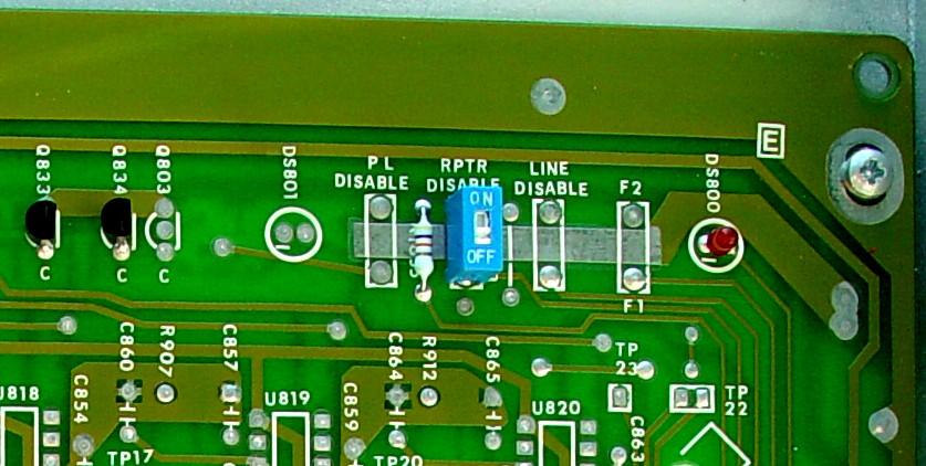
Here's the upper-left corner (when viewed with the station mounted to a wall) showing the area without the parts.
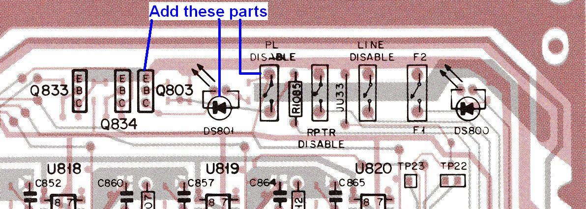
Here's the circuit board X-ray view of that same area.
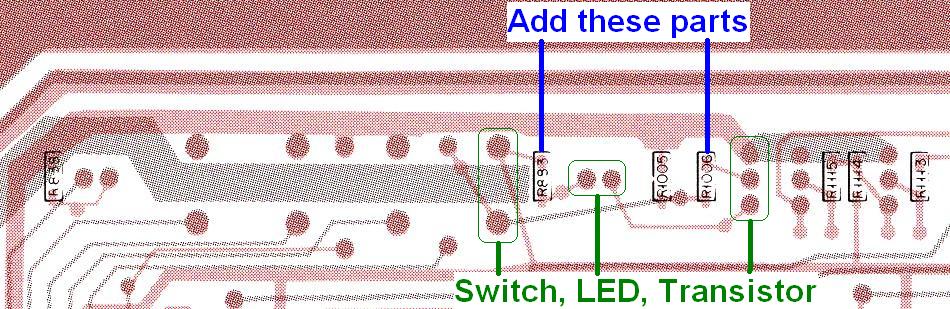
Here's the solder side of that same area.
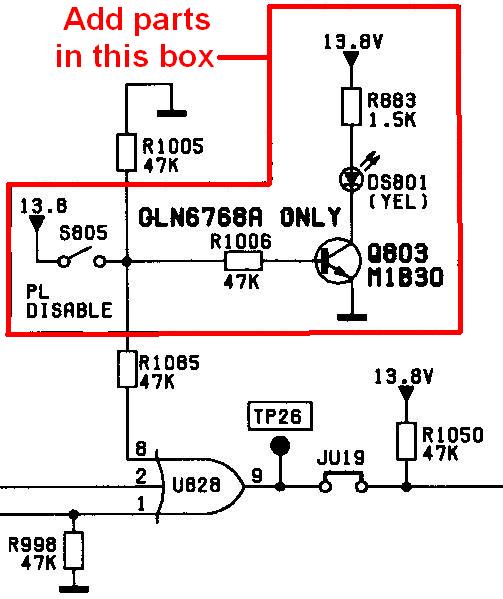
Finally, here's the schematic showing the parts we'll be installing.
Step-by-step procedure:
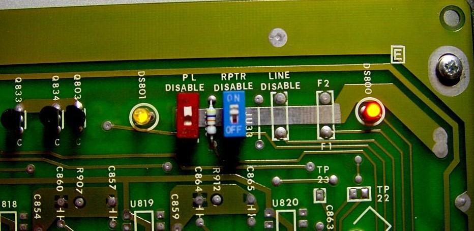
Here's what that area of the control board looks like with the parts installed. Both the PL DISABLE and RPTR DISABLE switches are turned on and their respective LEDs are illuminated.
The author may be contacted at: his-callsign [ at ] comcast [ dot ] net.
Back to the top of the page
Up one level (R100 index)
Up two levels (Motorola index)
Back to Home
This page originally posted on Tuesday 21-Jul-2009
Article text, artistic layout, and hand-coded HTML © Copyright 2008 by Robert W. Meister WA1MIK.
This web page, this web site, the information presented in and on its pages and in these modifications and conversions is © Copyrighted 1995 and (date of last update) by Kevin Custer W3KKC and multiple originating authors. All Rights Reserved, including that of paper and web publication elsewhere.