Up two levels (Moto index)
Back to Home
Motorola Spectra
Radio Configurations
Written by and Formerly Maintained by Robert Meister WA1MIK (SK)
Currently Maintained by Mike Morris WA6ILQ.

|
Up one level (Spectra index) Up two levels (Moto index) Back to Home |
Introduction to Motorola Spectra Radio Configurations Written by and Formerly Maintained by Robert Meister WA1MIK (SK) Currently Maintained by Mike Morris WA6ILQ. |
|
Many of the graphics can be displayed as larger images by clicking on them.
Major Differences At A Glance:
| Configuration | Local | Remote | Motorcycle |
|---|---|---|---|
| Low-/Mid-Power | Yes | Yes | Yes |
| High-Power | No | Yes | No |
| A2/A4/A5/A7 Heads | Yes | Yes | Yes |
| A3 (HHCH *) | Yes | Yes | Maybe |
| A9 (System 9000) | No | Yes | No |
| Dual Control Heads | No | Yes | Maybe |
Low-power radios transmit in the range of 4-15 watts. Mid-power radios transmit in the range of 20-50 watts. 800 and 900 MHz radios usually run at slightly lower power levels than VHF and UHF radios. High-power VHF and UHF radios operate with power levels of up to 110 watts.
All low- and mid-power radios can be mounted almost anywhere, and can have an A2/A4/A5/A7 control head mounted to the front of the chassis. For remote-mount configurations, the control cable plugs into a jack in a panel on the front of the radio in place of the locally installed control head. All other connections - main power, accessory, and antenna - are made at the back of the radio.
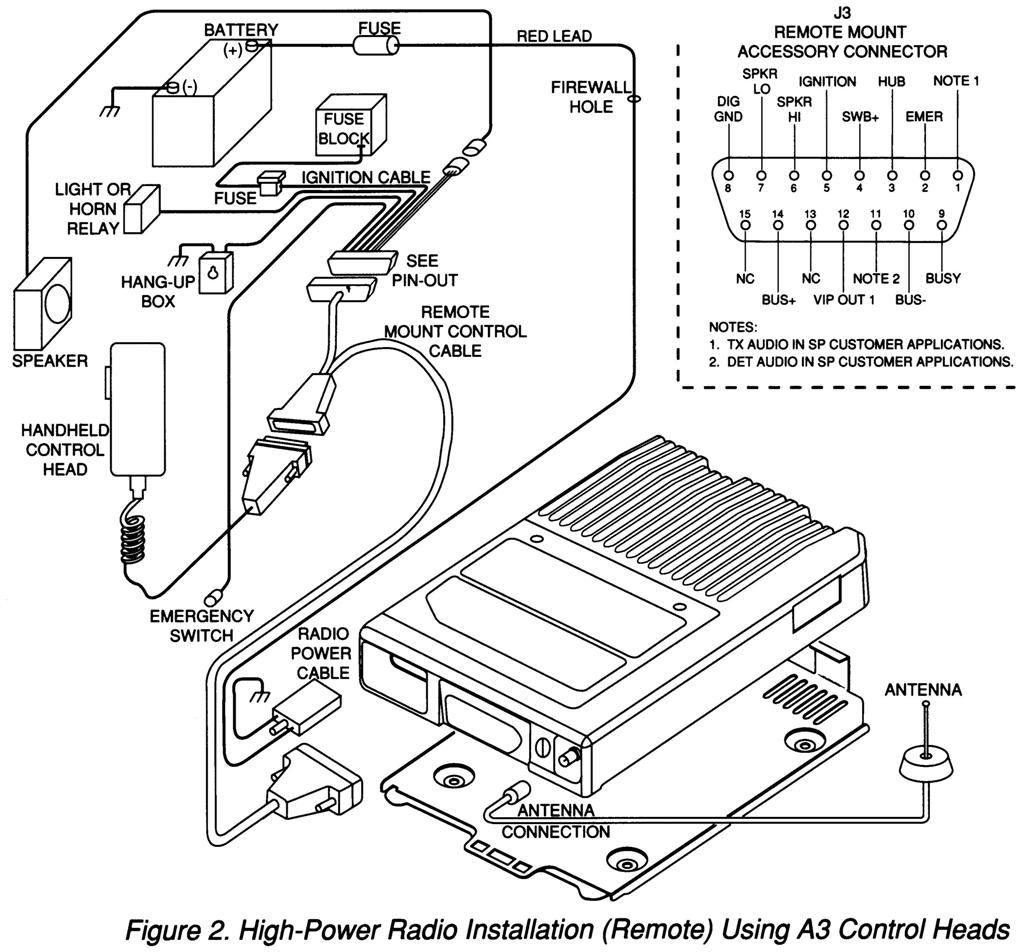
All high-power radios are remote-mount only. They have a mounting plate to which the radio is attached. A standard Motorola 2135 key locks the radio chassis to the plate. All cable connections - main power, control head, programming, and antenna - are made at the front of the radio. All high-power radios can use any control head with the proper cable harness and programming.
Control Heads:
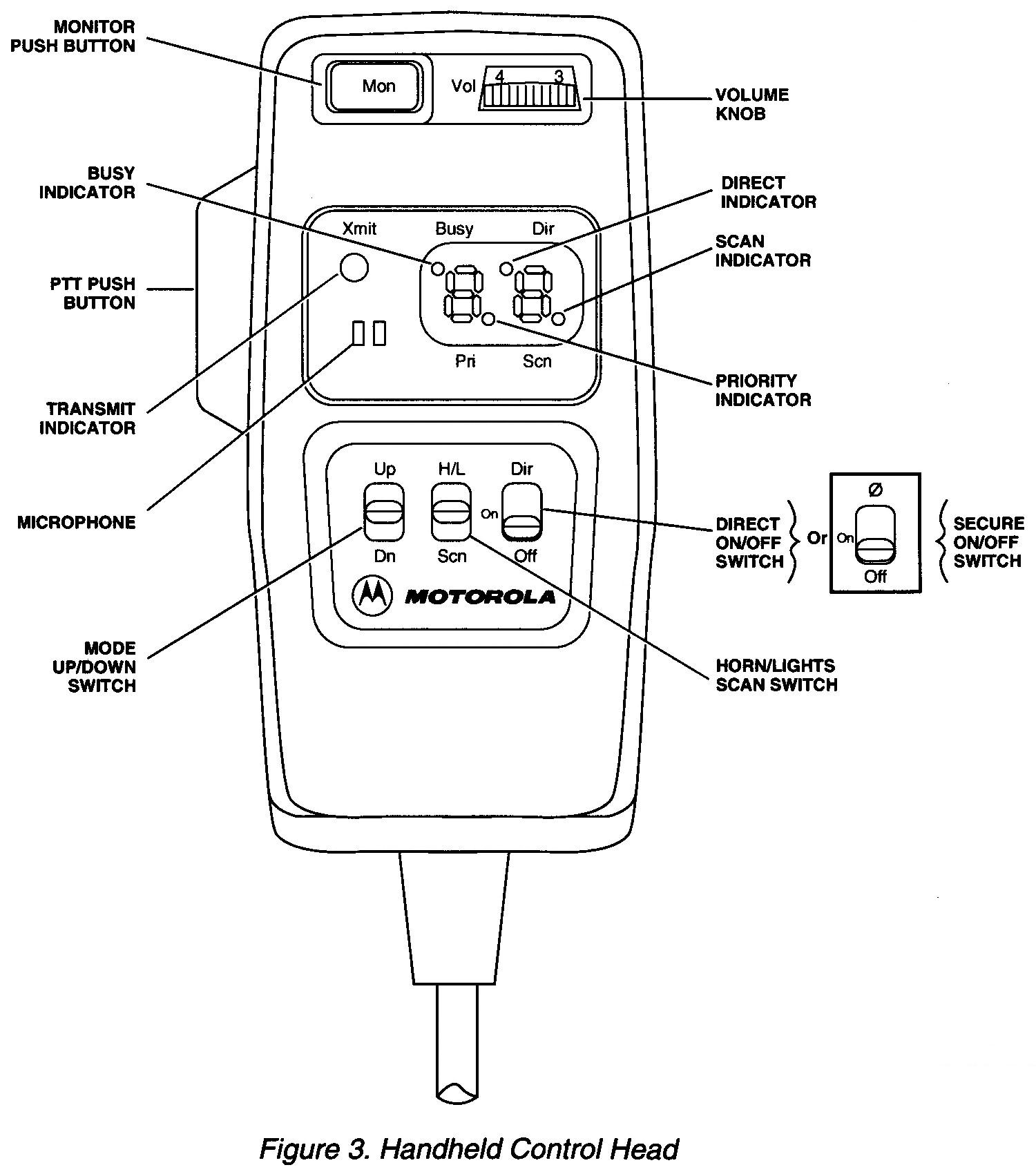
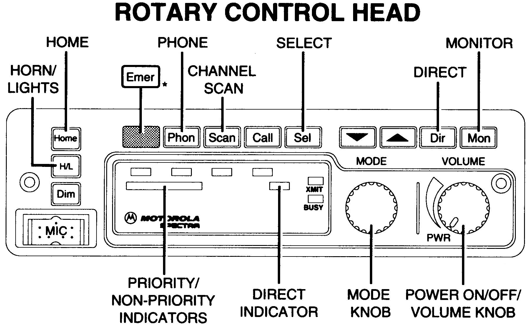
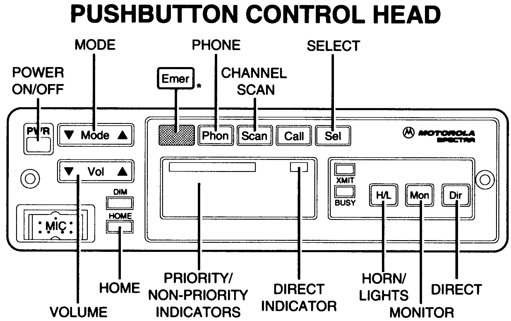
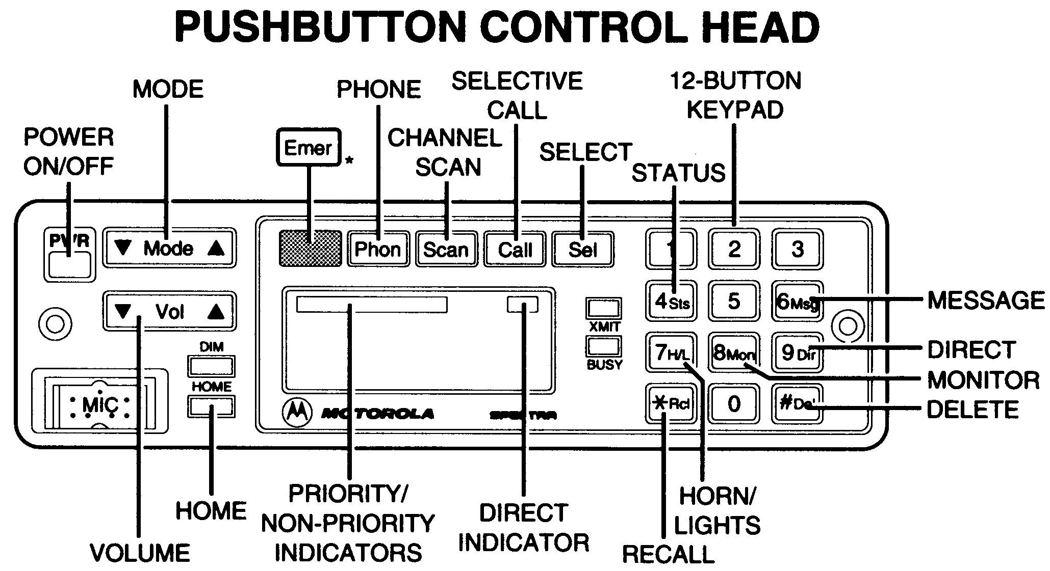
There are several different Spectra control heads available. The various features are detailed below. Click on the thumbnail images to see a full-size drawing or photo.
 |
 |
 |
 |
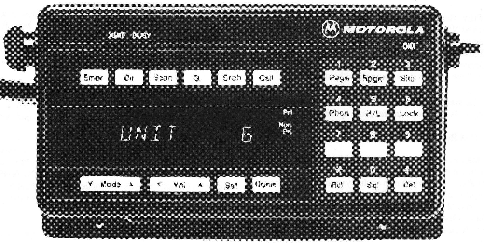 |
| A3 | A4 | A2/A5 | A7 | A9 |
|---|
All of the control heads mentioned in this article start with the letter "A". This letter describes the particular button legend combination on the control head. The letter and number are the 9th and 10th characters of the Spectra 12-character Model Number/ID. Other possible letters include "B", "C", and "E". Most people refer to the head using the letter "A" as a generic identifier.
| Model | Display | DTMF | Miscellaneous Information |
|---|---|---|---|
| A2 | VFD 8 | No | Less buttons than A5 head |
| A3 | LED 2 | No | Hand-Held Control Head |
| A4 | VFD 8 | No | Rotary Mode and Volume knobs |
| A5 | VFD 8 | No | Less buttons than A7 head |
| A7 | VFD 8 | Yes | Most Desirable Control Head |
| A9 | VFD 11 | Yes | Also known as System 9000 |
Local Radio Configurations and Connectors:
The control head is mounted directly to the front of the radio chassis, which is (usually) conveniently mounted near the operator, often under the vehicle's dashboard or in a console.
Power Levels: Only low- and mid-power radios can have control heads mounted to the front of the radio. High-power radios are trunk-mount only and have no provisions for a control head to be mounted in the front of them. The HHCH is an exception, since it attaches to the radio with a cable and allows the radio to be placed almost anywhere in the vehicle.
Control Heads: All control heads except the A9 head can be used with a dash-mount radio, however some may require a different or unique interconnect board, in particular, the HHCH and rotary knob heads (because they use an actual potentiometer in the head to control the receive volume). Dual control heads are therefore not possible. The microphone plugs into the front of the A2/A4/A5/A7 control head and into the rear of the A9 control head.
Main DC Power: A two-pin MaxTrac-style power connector is mounted on the power amplifier heat sink, at the rear of the radio. The exposed pin is positive.
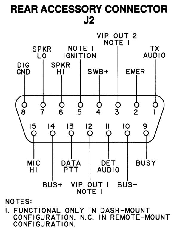
Accessories: The speaker, emergency switch, and ignition control wiring is handled through a rear-mounted DA-15 connector.
Rear DA-15 Accessory Jack: Handles the speaker, ignition control (one fused line), programming, emergency switch, and several VIP signals.
A note on Spectra speakers: The standard HSN4018B speaker is 8 ohms. An optional
HSN6001A speaker is available that is louder than the standard speaker due to the fact that
it is 3.2 ohms.
Never allow either radio speaker lead to go to ground. Grounding any/either speaker lead
(even momentarily) will destroy the audio amplifier chip on the Command Board and they are NLA.
Motorola sells an SLN6435A audio isolation transformer for connecting test equipment,
like a SINAD meter, to the radio speaker leads.
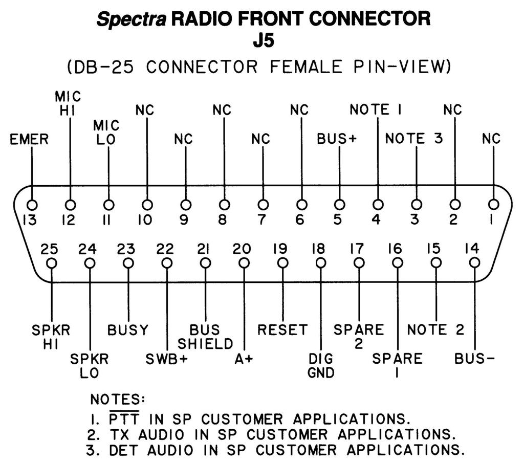
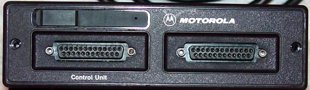
Front DB-25 Jack: The HHCH connects through this connector, however the radio itself can be mounted anywhere in the vehicle. This is the only dash-mount configuration that uses a DB-25 connector. Here's a typical front panel with a DB-25 jack for the control head (on the left) and another jack for options and programming (on the right).
Remote Radio Configurations and Connectors:
The control head attaches to the radio with a special cable. The radio end has a DB-25; the other end plugs into the control head using one of two unique connectors depending on the model and vintage.
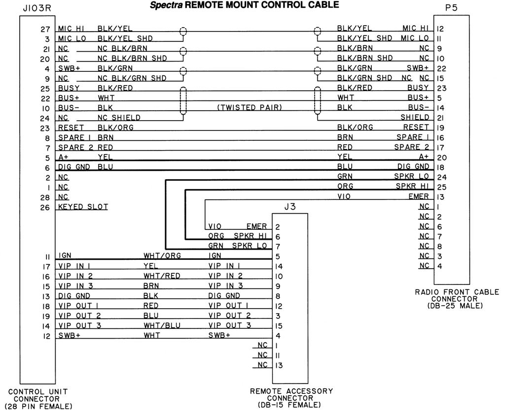
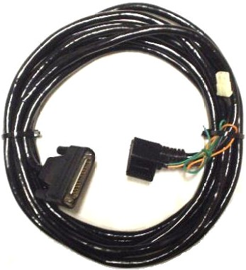
Here's a photo of the DD-50-style control cable (found on the web), which can plug directly into an A9 head or into an adapter board on A2/A4/A5/A7 heads. Note the orange and green ignition control wires (which should have in-line fuse-holders) and the two-pin white speaker connector.
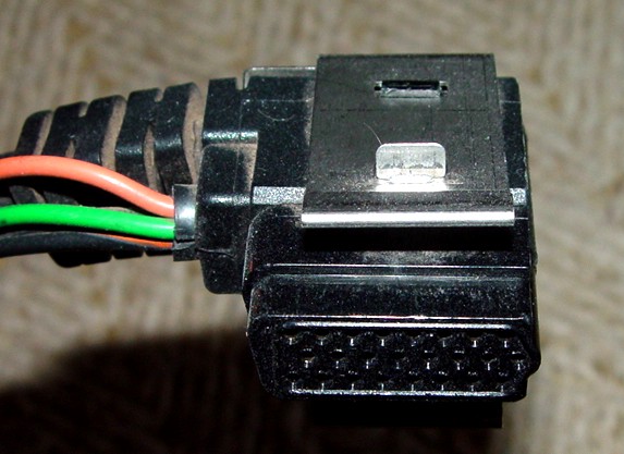
Here's a close-up of the connector and locking clip that's at the end of that cable. The clips do fall off occasionally.
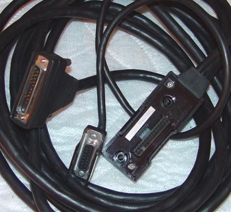
Here's a photo of the other style control cable, which can plug directly into A2/A4/A5/A7 heads. Note the DA-15 connector dangling from the control head connector; this is identical to the DA-15 accessory jack on the back of all low- and mid-power Spectra radios.
Accessories: The microphone plugs into the front of the A2/A4/A5/A7 control head, the rear of the A9 control head, or is built into the A3 HHCH. The speaker, emergency switch, and fused ignition control wires are provided at the control head end of the cable. Some control cables have discrete wires coming out of the connector; others have a DA-15 connector that accepts the same accessory plug that you'd use on a dash-mount radio. This connection point does NOT handle programming; all programming cables plug into a DA-15 connector at the rear of low- and mid-power radios, or a DB-25 connector on the front of high-power radios.

Main DC Power: Low- and mid-power radios use the two-pin MaxTrac-style power connector. High-power radios use a special three-pin power connector.
Rear DA-15 Accessory Jack: This jack seems to only be found on low- and mid-power radios and is used primarily for programming in remote-mount applications.
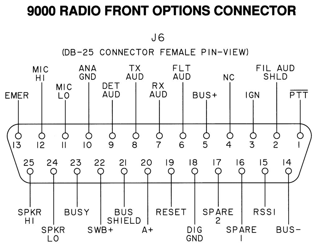
Front DB-25 Jack: One jack would be present for the control cable. Another jack is present on some low- and mid-power radios and all high-power radios for programming and other accessories, such as a siren/PA unit. Also, dual control head configurations can have a second head plugged in to this second DB-25 jack.
Front Secure-Net Programming Jack: Some remote-mount radio chassis have an additional jack in the upper left corner of the front panel, which is usually covered with a captive rubber flap. It appears to be a standard Spectra microphone connector, however only the outer four pins are connected. Here's a photo of a front panel with one.
Motorcycle Configurations:
All of these radios are remote-mount and share most of the qualities described above. The radio chassis is enclosed in a box behind the rider. There are unique cables for motorcycle installations and they use different pin-outs on some connectors. I've never seen one but I suspect there are special manuals that cover them; I'm sure Mike Blenderman's site has information about these.
There's no reason why an A3 (HHCH) head couldn't be used on a motorcycle radio, however it probably doesn't make sense for the driver to have to hold such a large microphone. Also, a dual control head configuration could be possible.
Control Head Configurations:
The A2/A4/A5/A7 heads have a two-row connector on the back of the head. This mates with an adapter board in the front of the radio chassis for dash-mount configurations. It can directly accept a mating connector on some remote-mount cables; these cables will have wires or a DA-15 connector up near the control head end for speaker and ignition control.
Some remote-mount head enclosures contain an adapter board that converts the two-row connector on the back of the head to the DD-50-style connector that's found on the back of A9 heads. This connector has provisions for a microphone plus several accessories. On A2/A4/A5/A7 heads that have the DD-50 connector on the back, the microphone can be plugged into either the front MIC connector or to the appropriate pins on the back of the control head.
A2, A4, A5, A7: The control cable plugs directly into the two-row connector on the back of the control head or into a DD-50 connector on an adapter board that the control head plugs into. All microphones plug into the front of the control head. Accessories are wired to the DA-15 connector on the control cables or at the radio.
The A5 and A7 control heads can be freely interchanged, requiring only minor changes in RSS to account for the DTMF buttons present on the A7 head. The A2 and A4 heads require more significant changes.
A3 (HHCH): The HHCH has a coiled cord with a DB-25 connector that plugs into a connector on the front of the radio, or into a mating connector on an extension cord. The microphone is built into the HHCH. Accessories are wired to the DA-15 connector on the control cable or at the radio.
A9 (System 9000): The control cable plugs directly into the DD-50 connector on the back of the control head. The microphone and wires for some specific external accessories plug directly into the back of the control head.
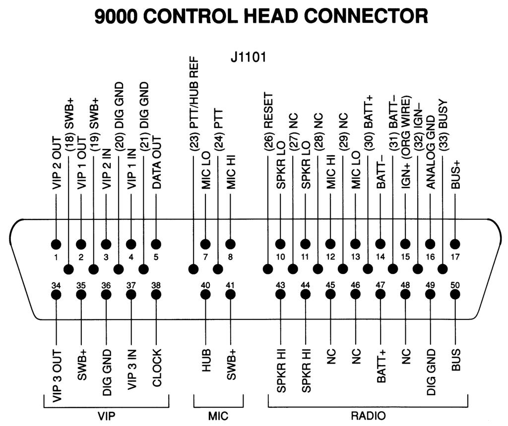
The System 9000 configurations also have unique cables and connectors.
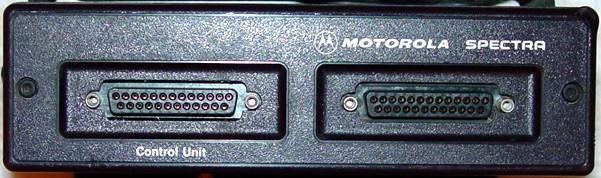
The two connectors on the front of the radio chassis are shown here.

Remote Cable Configurations:
Radio End: A DB-25 male connector plugs into the left DB-25 jack on the front of the radio. If there are two DB-25 connectors on the front of the radio, this is labeled "Control Head" or "Control Unit" depending on the radio's vintage.
Control Head End: Some cables have a three-row connector that mates directly with the DD-50 connector on the back of A9 control heads, or plugs into a DD-50 socket on an adapter board inside the control head enclosure for the A2, A5, and A7 control heads. Other cables use a two-row connector that mates directly with the A2, A5, and A7 control heads.
Speaker Jack: A two-pin Molex connector is provided at the control-head end of some control cables, or via a DA-15 accessory plug that plugs into a jack on the back of the radio chassis or into a mating connector at the end of other control cables.
Ignition Control Wiring: On radios using the DA-15 accessory jack, either at the end of the control cable or on the back of the radio chassis, one pin supports a fused ignition control input. Various operating conditions are configured with zero-ohm jumpers in the control head. Some control cables and radios without the DA-15 jack provide fused orange and green wires for separate ignition control of transmit and receive. See this article for more information about the ignition jumpers and orange and green wires.
The two major styles of remote-mount cables are shown below. Most of the differences are at the control-head end and whether there's a DA-15 hanging off a short piece of wire or just speaker and ignition wires.
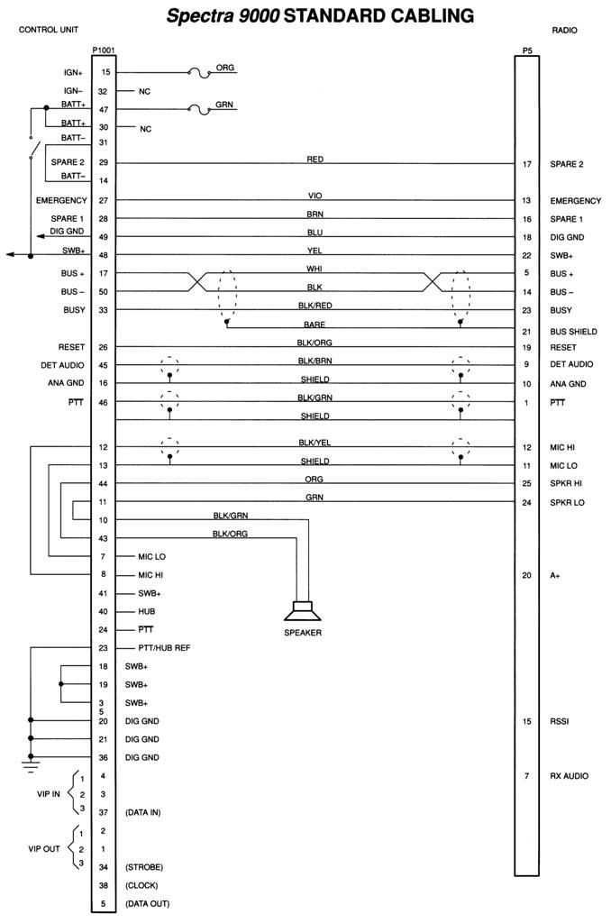
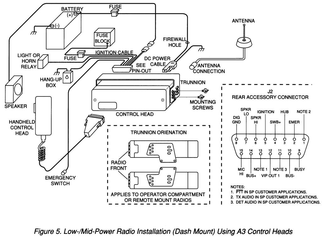
Installation Diagrams:
There are a lot of variations possible. The drawings below came from the installation Manual and show low- and mid-power dash-mounts, low- and mid-power remote-mounts, and high-power remote mounts.
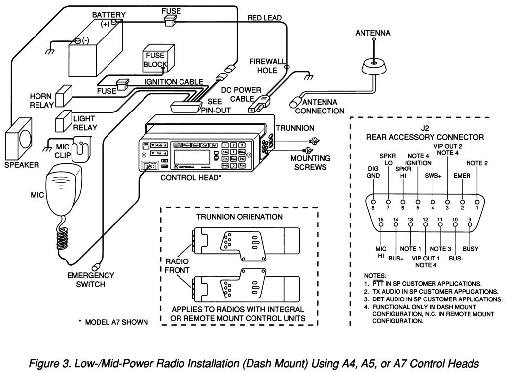
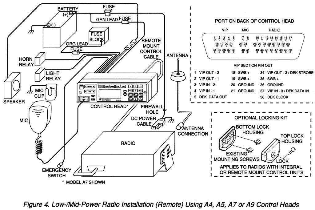
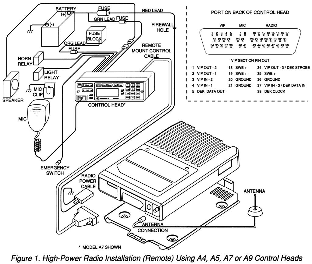
They chose to handle the A3 (HHCH) installations separately, but all three of the above configurations can also be accomplished with this control head.

Other Variations:
The Spectra and System 9000 radio equipment is very versatile and capable of a lot of unique configurations. Besides having dual control heads on one radio, you can also control two radios with one HHCH, although you can transmit on only one at a time. An external DTMF pad can be connected to some systms. Encryption (SecureNet) was available externally in a "security housing" or internally on some models. This is in addition to digital communications modes provided in the ASTRO Spectra radios. If the US Government wanted it, Motorola built it; that's why you see a lot of Spectra radios on government splits (403-430 MHz).
Acknowledgements and Credits:
Information came from several Spectra Basic Service Manuals as well as the Spectra Detailed Service Manual and a Spectra Installation Manual. Motorola has discontinued manufacture of Spectra products; as such, most of the manuals are No Longer Available.
Spectra and a bunch of other model-related items are trademarks of Motorola Inc.
Contact Information:
The author can be contacted at: his-callsign [ at ] comcast [ dot ] net.
Back to the top of the page
Up one level (Spectra index)
Up two levels (Moto index)
Back to Home
This page originally posted 06-Nov-07.
Article text, photographs (except where noted), and hand-coded HTML
© Copyright 2007 By Robert W. Meister WA1MIK.
This web page, this web site, the information presented in and on its pages and in these modifications and conversions is © Copyrighted 1995 and (date of last update) by Kevin Custer W3KKC and multiple originating authors. All Rights Reserved, including that of paper and web publication elsewhere.