Up two levels (Moto index)
Back to Home
By Robert W. Meister WA1MIK

|
Up one level (Spectra index) Up two levels (Moto index) Back to Home |
Spectra Interfacing By Robert W. Meister WA1MIK |
|
A lot of people have Spectra radios and wish to connect external equipment to them, such as repeater controllers, IRLP and EchoLink interfaces, and RIGblasters. In this article I will go through the available signals, and describe any special qualities you may need to deal with, to pass them to/from the outside world. You can decide which signals to make use of, and how to connect them to your equipment. There's no "best way" to do this. There are people that make custom interfaces for Spectras and I am not trying to interfere with anyone's business.
Important Notes:
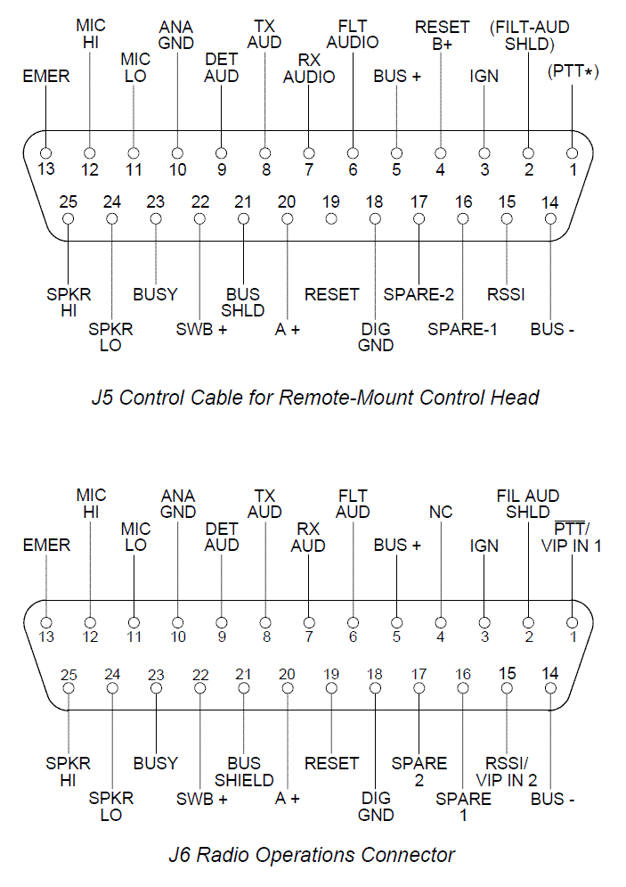
I used a 45 watt, 450 MHz radio as the basis for this article (ID # T44KXA7JA9AK, Model # TA9KX+068W) which was field-converted to a dash-mount, A7 model. My analysis took place on the command board and the 15-pin accessory jack. The accessory jack pins are the same for all low and medium power Spectra radios. They are described in my writeup on making your own low/medium power programming cable. You may have to do some additional investigation if you choose to use a high power or trunk-mount radio.
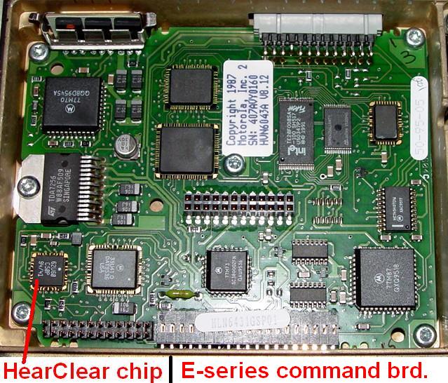
I also did some testing on my 30 watt, 900 MHz radio (ID # D37KGA5JE7AK, Model # DE7KG+110W). Note that this has an E-series command board with "SP" on the part number. The jumpers were not set up to provide the same signals on the accessory jack as the 450 MHz radio. The E-series command board, while electronically different, is plug-compatible with the regular command board, so all the signals on the various on-board connectors are the same as described here. There is no separate Memory Logic Module (MLM); these components are part of the command board. These also usually have HearClear circuitry built in, instead of being a plug-in option. Here's a photo of my E-series command board:
Many of the signals on the accessory jack are configurable via zero-ohm jumpers on the command board. Your radio may not be jumpered the same as mine, especially if you see SP (Special Purpose) at the end of the label on the command board. Half of these jumpers are on the solder side of the board and will require removal of the board for access. Ground the PTT input pin through a 1k resistor to make sure it works before you build up an interface cable and blow something up. Refer to the detailed service manual for information on jumper locations. I have NOT seen a chart detailing the function of these jumpers. If you have one, even a self-generated drawing, please consider donating a copy to repeater-builder.
Remember to wire the emergency signal (pin 2) to ground on all accessory plugs.
The two-row connectors used throughout the radio have different numbering schemes. Normally, such connectors have even-numbered pins on one row, and odd-numbered pins on the other. P503, which feeds the power amplifier, is oriented in this manner and iswhat I'd consider "standard". All the other connectors are numbered sequentially, starting at one corner and moving around the connector. This includes the MLM (Memory Logic Module) on the command board. This inconsistency is carried on to the RF power amplifiers, which vary by band and power.
Most audio signals have a positive DC voltage on them. When interfacing equipment to these signals, isolate them with a 10uF, 16V electrolytic capacitor, with the positive lead going towards the radio. Some external units may already have DC blocking capacitors in them, so check the schematics and save yourself some money.
Spectra mobile radios are very well built, and quite water-resistant. Gaskets and shields are used wherever possible. Bringing wires out of the radio is difficult because of the tight seals. There are no unused or spare pins on the accessory jack.
There is a ton of excellent connector and signal documentation on Mike Blenderman's Spectra web page. See http://www.onfreq.com/syntorx/spectra/boards.html for more information.
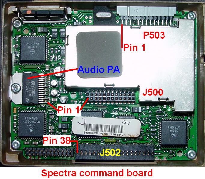
Here's a photo of the command board with the various connectors identified. These will be detailed below.
Ground:
Signal or digital ground can be found on pin 8 of the 15-pin accessory jack on the back of the radio. This is the same as the ground on the power connector. All of the signals on the accessory jack, except the speaker leads, use this pin as their return.
PTT Input:
This is probably the simplest one. Ground pin 13 on the 15-pin accessory jack on the back of the radio. This line rests at +4.75VDC and draws 80 microamps when grounded. Any open-collector small-signal NPN transistor can easily pull this line down. A relay will also work, but the low current on the contacts may create a reliability problem. This pin was the same on my 900 MHz E-series radio.
Transmit Audio Input:
This is also simple. Feed your audio through a capacitor to pin 15 on the 15-pin accessory jack on the back of the radio. This input is only good for voice audio, roughly 300 to 3000 Hz. The incoming signal will be pre-emphasized by the radio. You can't feed PL or DPL into this input. This line rests at +9.6VDC and draws 6.2 milliamps when grounded. It presents approximately a 560 ohm load. It has an input sensitivity of about 67 millivolts per kHz of deviation at 400 Hz (100 millivolts gave me 1.5 kHz deviation, 200 millivolts gave me 3.0 kHz deviation). These values are on a 450 MHz radio, 5 kHz deviation. Yours may vary; the sensitivity depends on how the deviation on your radio has been adjusted.
On my 900 MHz E-series radio, this pin was configured to perform a RESET function. I did feed audio into the front panel MIC jack through an old mike cord (these are handy since you can't buy the mike plug separately) and found exactly the same sensitivity: 70 millivolts for 1 kHz deviation with a 400 Hz tone. The same DC voltage is present on this jack as on the accessory connector.
Some documentation mentions pin 1 can also be used for transmit audio. You may have to pull the command board and move jumpers around to get that to work. It hasn't functioned on either of my two Spectra radios.
Spectras, and many other Motorola synthesized radios, have two transmit audio paths for modulation. One feeds the VCO (Voltage-Controlled Oscillator), the other feeds the low-frequency PL and DPL signals to the reference oscillator, to counteract the corrective action the PLL (Phase-Locked Loop) uses to keep the transmitter on frequency, which tends to cancel out PL or DPL signals. This is one reason why it would be difficult to provide your own PL or DPL signal to the transmitter. I suggest that you let the radio generate PL or DPL and just feed it voice audio through the accessory jack.
Receive Audio Output:
Here's where things get a bit more complicated. Pin 11 on the accessory jack has Detected Audio on it. This comes directly from the receiver's demodulator through a buffer amplifier. It is neither squelched nor de-emphasized. The output level is fixed, and there is DC voltage present on the signal, so use a DC blocking capacitor. The line rests at +4.8VDC and produces 200 millivolts with a 400 Hz tone at 1.0 kHz deviation. Noise produces about 1.25VAC. These values are on a 450 MHz radio, 5 kHz deviation. You must use this pin to feed an external PL/DPL decoder.
On my 900 MHz E-series radio, the same DC voltage was present. A 400 Hz tone set for 1 kHz deviation produced 148 millivolts on this pin, and it was quite linear through 3 kHz deviation. Noise produces about 580 millivolts. Remember, this is a narrow-band radio, with a maximum deviation of 2.5 kHz.
Note: The E-series radios have additional capabilities not found in other Spectras. One such feature is the Universal I/O Attenuator, which can be reached via RSS through the Service menu (F2), Advanced Alignment (F4), Universal I/O Attenuator Adjustment (F7), which is described in the manual:
F7 - The UNIVERSAL I/O ATTENUATOR Adjustment screen allows the user to modify the Spectra E's Universal I/O attenuator which basically affects the level of detected audio through the discriminator out line.
When you go to that screen, the RSS manual says:
This attenuator affects the level of detected audio through the discriminator out line. The default value is 0 and can be adjusted to a maximum of 19.05dB of attenuation. The range of the attenuator is from 0 to 127 with each step size corresponding to 0.15dB of attenuation.
Most late-model Motorola radios don't have a true discriminator; they have a quadrature detector to recover audio from the incoming FM signal. I'm sure the reference here is to the Detected audio signal coming out on the accessory jack pin 11.
You can also use the speaker output, pins 6 and 7 on the accessory jack, but there are certain things you must be aware of. Both of these leads are driven by the audio power amplifier IC. This gives the radio the ability to make lots of power and drive 2 ohm speakers. This means you must NOT ground either speaker lead, ever! Doing so will let the lifetime supply of magic smoke out of the audio amplifier, and you can only buy new ones from Motorola (the list price in August 2006 was $23.75 each, so blowing one up could be an expensive experience). Motorola tells you to use an isolation transformer when connecting anything to the speaker leads that might have one side grounded, such as test equipment or external devices. To quote from the Spectra Detailed Service Manual:
"The speaker outputs are at one-half of A+ and are directly connected to the speaker. The speaker outputs must NOT be grounded in any way. An audio isolation transformer must be used if grounded test equipment (such as a service monitor) is to be connected to the speaker outputs."
There's even a sticker on the speaker wires of the stock accessory/ignition cable (p/n 3080091M01) that says:
|
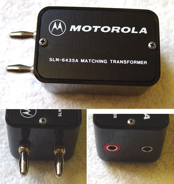
Motorola p/n SLN6435 is recommended in the service manuals; naturally these are no longer available. You could also use a 600-to-600 ohm transformer or even an 8-to-600 ohm transformer; either should be available at local electronics stores or good car audio shops. Another choice is a pair of 10 watt, 70V commercial audio speaker line transformers, connected back-to-back. I've seen these as cheap as $5 each.
Here's a real SLN6435A. Inside is a transformer, about 3/4 inch square, with four wires on one side (two coils wired in series) and two wires on the other, attached to a mounting bracket. One side of the plastic enclosure has a pair of banana plugs, the other side has a pair of banana jacks. The DC resistance is in the 30-40 ohm range for each side. Mine came with a short jumper cable with a Spectra speaker connector at one end (male pins) and a pair of banana plugs at the other end, so it's ready to be plugged into a Spectra (or similar) radio's speaker jack.
The speaker audio is squelched and de-emphasized, but there is also about 7VDC on each of the leads when audio is present, and up to 8VAC at maximum volume. These lines go nearly to ground when the radio is squelched. This DC voltage shift can be put to some use as a COR signal; more about that later. Only normal voice audio (300 to 3000 Hz) will make it through to the speaker leads, so you can't feed an external PL or DPL decoder from these pins.
The speaker audio output is, of course, controlled by the front panel volume control. This may be a problem in certain applications. Also, if you press certain front panel buttons, you could get a "beep" out of the speaker output. The E-series radio naturally has the same speaker audio characteristics.
You could use a capacitor and connect your equipment to one speaker lead or the other, but the DC shift that's produced when the radio mutes or un-mutes will cause a very audible thump in the recovered audio. Use a transformer as recommended above.
What the radio needs, but does not initially seem to have, is a muted, de-emphasized, constant-level signal from the receiver. MaxTracs have it; Spectras don't, at least not where it's convenient. After reading the theory of operation, I found a signal called Filtered Audio which appears on the command board's control head connector, J502 pin 5. While not easy to get to, or route to someplace useful, it is exactly what the doctor ordered. This pin provides clean received audio; no beeps or other stuff interferes with it. It's de-emphasized, muted (audio only appears here when the radio opens squelch or the proper PL/DPL has been decoded), and has 60 millivolts per kHz of deviation at 400 Hz on my 450 MHz radio, with a 6dB per octave roll-off. This audio level will be different on a 900 MHz radio. It's buffered, so there will be +4.8VDC present on that pin; that means you need to use a DC blocking capacitor in series with your equipment.
Received Signal (Carrier) Indicator:
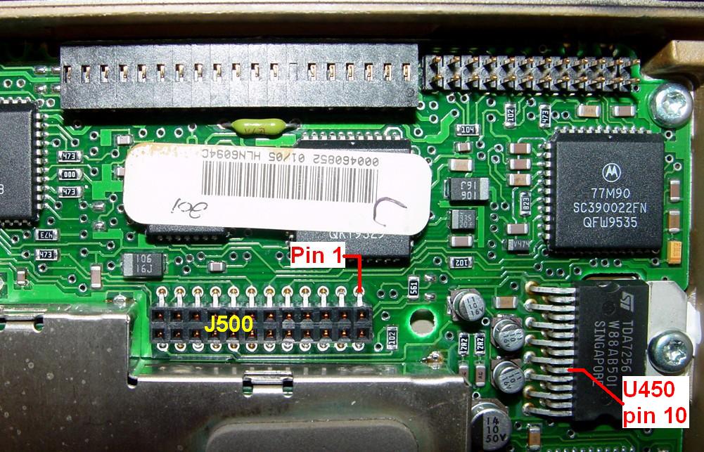
The Channel Activity signal coming from the RF board appears at the command board J500 pin 7. This signal goes to +5V when there is activity or an open squelch condition. This same signal was present on my E-series radio.
The microprocessor on the command board turns on the BUSY LED on the control head when the Channel Activity signal is high. If there is activity or the squelch is open, the BUSY LED will be on. This is independent of any other muting of the audio.
The audio PA (Power Amplifier) IC is enabled by the AFIC (Audio Filter IC) with a +10VDC signal that turns the amplifier on whenever the radio properly decodes an input signal's PL/DPL or when the radio has to make an audible beep sound, such as when you press certain control head buttons. This signal is found on U450 pin 10 (see the photo of J500 below for the location of this pin). If the radio's MONITOR function is set ON, or the channel being received does not require PL or DPL, then the radio will unsquelch, the audio amplifier will be enabled, and you will hear any incoming signal. The E-series radio had the same characteristics.
The activation of the audio amplifier also raises both speaker leads to about +7VDC.
This rise can be sensed and used to drive external circuitry, either through a relay or
some solid-state devices. Note that there will be some variation on the speaker line
voltage due to the presence of audio, so you might need some additional components to
deal with this. I have seen a circuit consisting of a diode in series with a 250 ohm, 5
volt DC relay from one the speaker lead to ground, with a protection diode across the
relay coil. You can use 1N4148 diodes. The following "ASCII" schematic shows the circuit:
                    +------|<--------+
                    |     diode      |
             diode  |                |
(Acc. Pin 6)--->|---+--(relay coil)--+---(Acc. Pin 8)
PL and DPL are detected internally by the microprocessor on the command board. There is no external indication that a valid coded squelch signal has been received. The microprocessor uses this information, together with various other receiver-generated signals, to decide when to un-mute the audio amplifier.
An alternative circuit was suggested by Kris KE4AHR. It eliminates the possible audio variation in a speaker-derived COS signal rather elegantly. I have actually built this circuit and it does work very well, however there are a few things you need to know about it:
With these two caveats, here's a simple way to extract a decent COS signal from the
speaker leads. The two speaker leads (pin 6 and pin 7 on the accessory jack) provide
about +7VDC when the receiver unsquelches. The two 1k resistors isolate the speaker
wires and provide a high impedance tap. The 100 ohm pot is adjusted to eliminate or
null any audio present at the arm of the pot. It can be eliminated if you use precision
resistors. The 470 ohm resistor going to ground provides a pull-down when the radio
squelches up again. The COS signal is taken from the ungrounded end of the 470 ohm
resistor. None of these values are critical. Expect about +3VDC on the COS line,
referenced to ground, when active.
(pin 7)o-----\/\/\/\-----+
                1k       |
                         \
                    100  /        470
                    ohm  \<--+--\/\/\/\-----o(pin 8)
                    pot  /   |
                         \   +-----> COS Signal
                1k       |
(pin 6)o-----\/\/\/\-----+
Accessory Connector Interconnect:
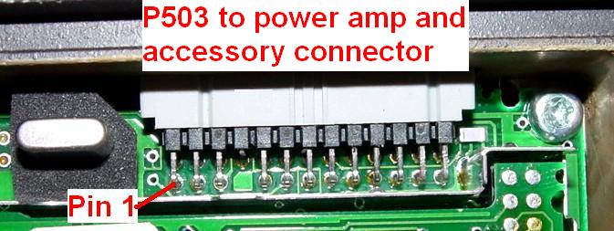
P503 at the back edge of the command board accepts a flat cable that feeds the power amplifier and the 15-pin accessory jack on the back of the radio. The wiring of this cable is only present in the basic service manuals. I have reproduced part of it here. The first 12 signals go to the power amplifier.
| Cmd Pin |
P503 Signal Name |
Acc. Pin |
|---|---|---|
| 01 | Control Limit | --- |
| 02 | Control Drive | --- |
| 03 | Cur. Sense + | --- |
| 04 | Keyed 9.4V | --- |
| 05 | A+ | --- |
| 06 | Temp. Sense | --- |
| 07 | KEYWAY | --- |
| 08 | Fwd. Voltage | --- |
| 09 | A+ | --- |
| 10 | 9.6V | --- |
| 11 | Cur. Sense - | --- |
| 12 | Digital Ground | 8 |
| 13 | Microphone Hi | 15 |
| 14 | Speaker Lo | 7 |
| 15 | Bus + | 14 |
| 16 | Speaker Hi | 6 |
| 17 | PTT | 13 |
| 18 | Ignition Sense | 5 |
| 19 | VIP Out 1 | 12 |
| 20 | SWB+ | 4 |
| 21 | Detected Audio | 11 |
| 22 | VIP Out 2 | 3 |
| 23 | Bus - | 10 |
| 24 | Emergency | 2 |
| 25 | Busy | 9 |
| 26 | TX Audio | 1 |
Connector orientation:
Looking over the top of the command board towards the power amplifier:
| 01 | 03 | 05 | --- | 09 | 11 | 13 | 15 | 17 | 19 | 21 | 23 | 25 |
| 02 | 04 | 06 | 08 | 10 | 12 | 14 | 16 | 18 | 20 | 22 | 24 | 26 |
A flat cable comes from the power amplifier to mate with this connector, making access somewhat difficult. The MLM shield is very close to the back of this connector on those command boards that have an MLM (E-series boards do not). The odd numbered (top row) pins are accessible from the back of the connector. VIP Out 1 (P503 pin 19) which appears on the 15-pin accessory jack pin 12, would be a great place to bring a signal out of the radio. In fact, there's a jumper position under the command board to route the Channel Active signal to this pin. Just make sure the VIP Out lines are not programmed for use. They originate in the control head, are open-collector, and are typically used to operate relays for horn and lights.
RF Board Interconnect:
The RF board underneath the radio interfaces with the command board on top of the radio via a 24-pin connector, J500. The signals are documented below and were measured with the radio in receive mode. The orientation of this connector on the command board is also shown below.
Note that pin 7 or pin 8 of J500 is a great TTL-compatible channel activity signal which comes from the RF board. It's easy to get to and a resistor/transistor COR buffer circuit can easily be attached to the solder pad next to the connector.
| Pin | Name | Description and Signal |
|---|---|---|
| 01 | +5V | Power for ref. osc. only |
| 02 | Ref. Tune | Frequency warp voltage |
| 03 | Spare-1 | |
| 04 | Demod. Out | Raw RX audio |
| 05 | Squ. Att. Out | High frequency noise |
| 06 | Squ. Att. In | Squelch setting input |
| 07 | Channel Act. | +5V with open squelch |
| 08 | Squ. Mute | +5V with open squelch |
| 09 | RSSI | 0.71V idle, 2.1V max signal |
| 10 | +9.6V | +9.6VDC |
| 11 | VCO Mod. | Goes directly to the VCO |
| 12 | A+ | +13.8VDC |
| 13 | Spare-2 | |
| 14 | Lock | Synthesizer locked = 0V |
| 15 | Keyed 9.6V | 9.6V on transmit |
| 16 | Prescaler Sel. | Low to select prescaler |
| 17 | REF Mod. | Modulates the synthesizer |
| 18 | Data | For programming ICs |
| 19 | Clock | For programming ICs |
| 20 | Synth. Sel. | Low to select synthesizer |
| 21 | 2.1 MHz | Audio clock signal |
| 22 | Ground | |
| 23 | Ground | |
| 24 | Ground |
J500 connector orientation:
Front of radio above, audio amplifier IC to the right:
| 12 | 11 | 10 | 09 | 08 | 07 | 06 | 05 | 04 | 03 | 02 | 01 |
| 13 | 14 | 15 | 16 | 17 | 18 | 19 | 20 | 21 | 22 | 23 | 24 |
I went through all of the test signals on my two radios, generated from the front panel menu, and measured the frequency and level at the VCO Mod and REF Mod pins of J500 as well as the total deviation. The results are summarized below. The VCO Mod signal contains the majority of the modulation energy; the REF Mod signal is necessary primarily at low frequencies for PL and DPL. Tone frequencies are in Hz. VCO and REF levels are in millivolts AC (RMS). Deviation is in Hz.
| Radio Display |
Signal Use or Description |
Tone Freq |
450 MHz Radio | 900 MHz Radio | ||||
|---|---|---|---|---|---|---|---|---|
| VCO | REF | Dev | VCO | REF | Dev | |||
| PL | PL | 100 | 98 | 232 | 720 | 64 | 80 | 440 |
| PC | PL Compensation | 11 | 97 | 228 | 790 | 62 | 76 | 340 |
| PD | PL Deviation Adj. | 67 | 104 | 246 | 760 | 68 | 84 | 470 |
| DL | DPL | 100 | 89 | 211 | 650 | 49 | 61 | 340 |
| LS | Low-speed trkg. | 100 | 135 | 320 | 980 | 68 | 85 | 470 |
| M6 | MDC-600 | 1500 | 458 | 1070 | 3380 | 323 | 400 | 2140 |
| MC | MDC-1200 | 1500 | 470 | 1110 | 3470 | 323 | 400 | 2130 |
| HS | High-speed trkg. | 1500 | 436 | 1030 | 3220 | 302 | 372 | 2000 |
| DF | DTMF '#' digit | Note | 310 | 787 | 3130 | 207 | 255 | 1920 |
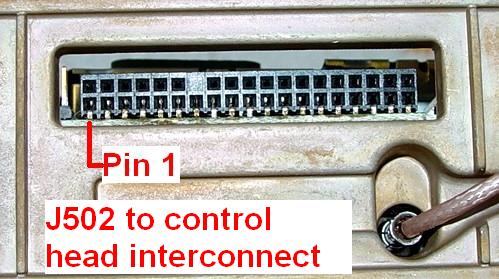
Control-head Connector:
The control head communicates with the command board via J502. Various adapters (interconnection boards) select the appropriate signals and feed them to a local (dash-mount) control head or through a cable to a remote control head. Not all signals make it through to the control head. Note that all of the standard signals on the accessory jack can also appear here, if the command board jumpers are set correctly. Here's a short description of the signals on this connector.
| Pin | Name | Description and Signal |
|---|---|---|
| 01 | +9.6V | |
| 02 | A3 Volume | |
| 03 | Emergency | Acc. Jack pin 2 |
| 04 | Channel Active | +5V with carrier or unsq. |
| 05 | Filtered Audio | Muted, De-emph. Rx. Audio |
| 06 | Microphone Hi | Acc. Jack pin 15 |
| 07 | Ground | Acc. Jack pin 8 |
| 08 | Receive Audio | |
| 09 | Busy | Acc. Jack pin 9 |
| 10 | Ground | Acc. Jack pin 8 |
| 11 | Reset | |
| 12 | Transmit Audio | Acc. Jack pin 1 |
| 13 | Detected Audio | Acc. Jack pin 11 |
| 14 | Spare 1 | |
| 15 | SecureNet | |
| 16 | SecureNet | |
| 17 | VIP Out 2 | Acc. Jack pin 3 |
| 18 | VIP Out 1 | Acc. Jack pin 12 |
| 19 | Data | |
| 20 | Transmit Data | |
| 21 | Ignition | Acc. Jack pin 5 |
| 22 | Bus - | Acc. Jack pin 10 |
| 23 | SecureNet | |
| 24 | PTT | Acc. Jack pin 13 |
| 25 | Bus + | Acc. Jack pin 14 |
| 26 | Data | |
| 27 | Spare 2 | |
| 28 | Ground | |
| 29 | A3 Data In | |
| 30 | A+ | |
| 31 | SWB+ | Acc. Jack pin 4 |
| 32 | KEYWAY | |
| 33 | Clock | |
| 34 | Speaker Lo | Acc. Jack pin 7 |
| 35 | Speaker Hi | Acc. Jack pin 6 |
| 36 | UNSW 5V | |
| 37 | +5V | |
| 38 | VAG | Audio Ground |
Connector orientation:
Looking into the front of the radio at J502:
| 38 | 37 | 36 | 35 | 34 | 33 | --- | 31 | 30 | 29 | 28 | 27 | 26 | 25 | 24 | 23 | 22 | 21 | 20 |
| 01 | 02 | 03 | 04 | 05 | 06 | 07 | 08 | 09 | 10 | 11 | 12 | 13 | 14 | 15 | 16 | 17 | 18 | 19 |
Note that pin 5 (Filtered Audio) and pin 4 (Channel Active) are both on the bottom edge of the connector. These pins are not accessible on the command board because they're underneath J502 and along the front edge of the board, but you might be able to tack a wire directly to the pad under these pins and route them back into the radio.
If you connect J502 pin 30 (A+) to J502 pin 31 (SWB+), the radio will power up without the control head present. All other signals should then be usable. For trunk-mount radios, you can use a DB25M connector and add a jumper from pin 20 (A+) to pin 22 (SWB+) and plug this into the front panel control head DB25F receptacle to get the radio to power up without a control head attached.
Pin 5 (Filtered Audio) is de-emphasized and muted, and the level is 60 mVAC per 1 kHz of deviation at 400 Hz tone, and 26 mVAC per 1 kHz of deviation at 1000 Hz tone.
Pin 13 (Detected Audio) is neither de-emphasized or muted. It's raw full-range audio of about 195 mVAC per 1 kHz of deviation at any frequency.
Many of the signals presented at J502 are routed to the two DB25F connectors on the front panel of remote-mount radios. The following image was extracted from the Basic Service Manual:
Test Equipment Utilized:
Acknowledgements and Credits:
IRLP is a trademark of the Internet Radio Linking Project.
EchoLink is a trademark of Synergenics LLC.
RIGblaster is a trademark of West Mountain Radio.
Spectra, PL, DPL, HearClear, and a whole lot of other terms are trademarks of Motorola, Inc.
Signal and schematic information was obtained from the Motorola Spectra Basic (UHF) Service Manual, p/n 6881071C05, and the Motorola Spectra Detailed Service Manual, p/n 6880102W61. The RSS User's Guide, p/n 6880101W48, was also useful.
Thanks always go to Mike WA6ILQ of the repeater-builder.com staff for taking an MS Word DOC file and a handful of photos and converting it into something presentable.
All photographs in this article were taken by the author.
Contact Information:
The author can be contacted at: his-callsign [ at ] comcast [ dot ] net.
Back to the top of the page
Up one level (Spectra index)
Up two levels (Moto index)
Back to Home
This article was created in August 2006.
Article text and photographs © Copyright August 2006 By Robert W. Meister WA1MIK.
Hand-coded HTML © Copyright 2006 and date of last update by Mike Morris.
This web page, this web site, the information presented in and on its pages and in these modifications and conversions is © Copyrighted 1995 and (date of last update) by Kevin Custer W3KKC and multiple originating authors. All Rights Reserved, including that of paper and web publication elsewhere.