
| Back to Home | Technical Information on S‑COM Repeater Controllers |
Compiled and HTML'd by Mike Morris WA6ILQ
Web page maintained by Kevin Custer W3KKC
and by Mike Morris WA6ILQ
Click here or on the logo above to go to the S-COM factory website
Note that the S-Com factory still supports all of the 5K, 6K, 7K and 7330 controllers, including spare parts stock (to the limit of parts availability).
| Contact: | S-COM, LLC | Contact Bob Schmid directly at bob (at) scomcontrollers (dot) com For reference, the prior address (seen in many old manuals) was Box 1718 in Loveland, Colorado. |
|
| PO Box 1546 | |||
| LaPorte, Colorado, USA 80535-1546 | |||
| Voice: (970) 416-6505 | |||
| Fax: (970) 419-3222 | |||
| E-mail: sales (at) scomcontrollers (dot) com or support (at) scomcontrollers (dot) com |
The S-Com corporate web site has a wealth of information at http://www.scomcontrollers.com.
There are two Scom mailing lists:
Click here for the main list (all Scom products).
Click here for the 7330 list.
There is a large user community on the mailing lists, plus the principals are active members of the list.
Scom has produced four controllers over the last 30 years. The programming language is very
similar between models. Each model built on the architecture of the prior model.
Support for all four models is still available and is limited only by the availability of replacement parts.
The four models are:
| A Few S-Com Notes by Mike Morris WA6ILQ | |
| The Vyex Digital Audio Board - a replacement for the S-Com 7K speech synthesizer board... Bring your 7K up to date! Off-site pointer (opens in a new browser tab) | |
| S-Com Connector pinout Covers the models 5K, 6K, 7K and 7330 by Mike Morris WA6ILQ | |
| Various Technical Notes on S-Com products by
Mike Morris WA6ILQ Including some notes on serial communications with the 7330 or the 7K DAB. |
|
| Sample programming
for the S-Com repeater controller line By Joel Huntley WA1ZYX (Off-site
link, opens in a new browser tab) Programmers would call these "code fragments" - just little tricks and treats that others have developed and decided to share. |
|
| S-COM 7K to MICOR station interfacing
(19 kB PDF file) By Bob Hoffman N3CVL. This file was recreated from old postscript files. Diagrams only; no text. |
|
| Another connection
of a repeater controller (an S-COM 7K) to the MICOR Unified Chassis Station By
Joel Huntley WA1ZYX (Off-site link, opens in a new browser tab) Also applies to the 5K, 6K or 7330 with only connector pin number changes. |
|
| Interfacing
a GE MASTR II Base Station / Repeater to a S-Com 5K or 7K (19 kB PDF file) By
Bob Schmid WA9FBO of S-Com, LLC. Also applies to the 6K or 7330 with only connector pin number changes. |
|
| Interfacing a Uniden Repeater to an S-Com 5K (108 kB PDF file) Also applies to the 6K, 7K or 7330 with only connector pin number changes. |
|
| Interfacing an MSF5000 Repeater to an
S-Com 7330 (372 kB PDF file) By Justin Reed NØUJQ Also applies to the 5K, 6K or 7K with only connector pin number changes. |
|
| Interfacing a Kenwood
TKR-720 or TKR-820 repeater to an S-Com 5K By John "Jake" Eckardt N3FU Just change the pin numbers for the 6K, 7K or 7330. |
|
| Recovering the extra
User Function Outputs from an S-COM 7K By Andy Zorca WJ9J Eight additonal digital outputs are available from a 7K controller. Here's a schematic of the hardware to do it, along with a complete description of the programming. |
|
| Configuring the
S-Com 6K to Operate a Link Transceiver A thorough step-by-step walkthrough, including
programming, by Justin Reed NØUJQ The technique also applies to the 7K or 7330 with connector pin number changes. |
|
| Programming your S-Com 5K, 6K or 7K repeater
controller without a radio or a phone line By Mike Morris WA6ILQ The S-Com 5K, 6K and 7K controllers do not have a serial port (unless your 7K has a DAB). Here's how to get around that. This technique also works with any brand of controller that understands DTMF. |
|
| Analog Audio Delay Module Schematic (ADM) This is the early analog delay module. Most had two of the pots sealed with glyptal - Don't mess with the sealed pots! This is the voice of experience... | |
| Digital Audio Delay Module Schematic (DADM) This is the later digital delay module. Switch setting info is here: http://www.scomcontrollers.com/node/26. | |
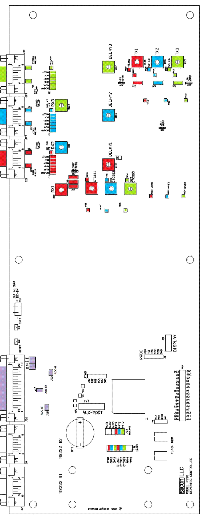
| S-Com 7330 Board Layout This is worth printing on a color printer and putting inside the case of the controller. | |
| The 7330 has a non-rechargeable 3-volt lithium coin cell (a common
BR2032 or CR2032) to maintain memory data and keep track of the time
and date during power outages and while in storage. The cell is socketed
on the main board for easy replacement. The cell will last for several years
with power off. However, if the 7330 is stored for a long period of time,
it is a good idea to replace the coin cell before putting the controller back
into service. Suggestion: Put a label on the front of the controller with the battery replacement date, something like "CR2032 coin cell replaced 11-2024 by (name), replace in 11-2029." |
|
| The 7330 has four system configuration memories named CONFIG_A through CONFIG_D. Suggestion: If you are new to the 7330 save the factory shipped configuration in CONFIG_D. Then if you get lost or if the 7330 locks up (very rare) you can restore CONFIG_D to the running configuration and recover the system. That leaves CONFIG_A through C for your current, alternate and development / test configurations. |
One trick that has been done to confuse folks that want to play with your system is to use a courtesy tone that is commonly used by another brand of controller. The ACC page at this web site has a PDF that describes the factory shipped courtesy beeps. They are included in the courtesy tones collection page (trust me - the "Nextel Beep" is cute, but becomes real annoying after a while).
One convenient method of connecting any radio to a repeater controller: Take a common VGA computer monitor cable and chop off the connectors (frequently colored blue). You will find three shielded conductors (was used for red, green and blue data) plus 7 conductors (frequently three twisted pairs and one individual conductor, but not always). I've found some VGA cables have a braided shield (like RG-8 shield). Use the 3 individually shielded conductors for RX audio, TX audio and external PL Encode audio (if you need / use it), and the twisted pairs and one loose conductors can be used for everything else... ground, COR, PL Decode (TOR), PTT, etc. I've found the VGA cables at thrift stores for $1 to $3 each.
Back to the top of the page
Back to Home
This web page created 02-Apr-2007.
Information and images published with cooperation and permission of S-COM LLC, All Rights Reserved.
This web page, this web site, the information presented in and on its pages and in these modifications and conversions is © Copyrighted 1995 and (date of last update) by Kevin Custer W3KKC and multiple originating authors. All Rights Reserved, including that of paper and web publication elsewhere.