Motorola index
Back to Home
the 900 MHz MaxTrac VCO
Expanding The Range To
Receive And Transmit Over
The Entire Amateur Band
By Robert W. Meister WA1MIK

|
MaxTrac index Motorola index Back to Home |
Analysis and Modification of the 900 MHz MaxTrac VCO Expanding The Range To Receive And Transmit Over The Entire Amateur Band By Robert W. Meister WA1MIK |
|
The 900 MHz VCO:
The VCO is the Voltage-Controlled Oscillator that's part of the synthesized frequency generator on the radio's RF board. All programmable (synthesized) radios have one or more VCOs. Sometimes one is used for the receiver and one is used for the transmitter; in this case, only the transmitter VCO needs to be modulated.
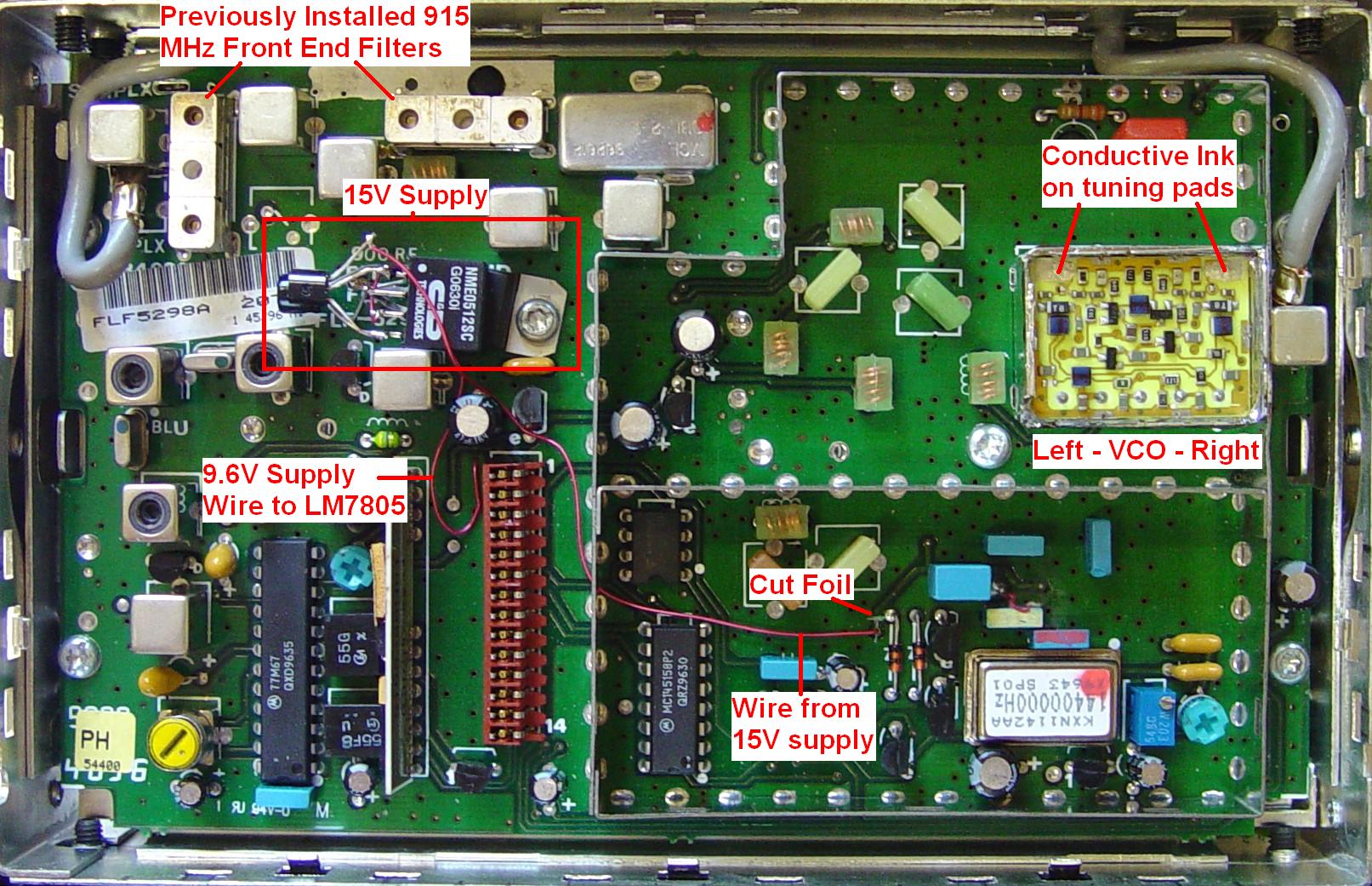
The 900 MHz MaxTrac VCO actually contains two similar circuits, only one of which operates at a given time. Upon opening the VCO, you can see the orientation. Everyone refers to the two circuits as the "left" and "right" VCOs, even though they're both in one sealed enclosure. Refer to the photo below of an unmodified VCO:
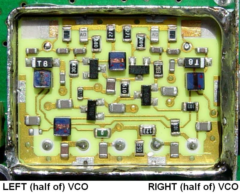
The active half selection is determined by the voltage on pin 5 of the VCO. This is controlled by the microprocessor on the logic board via a signal called "pin shift". This can be found on pin 14 of the inter-board connector that goes between the RF and logic boards. When this signal is high, the input at the VCO is low and the left section of the VCO is active. The service manual states that pin 14 is high for non-talk-around (and receive), and low for talk-around. With conventional firmware, any transmit frequency of 903.0 MHz and higher is considered talk-around, and the right half of the VCO will be utilized. This value is different if the radio has trunking firmware.
Note that the inter-board connector's signal names for 900 MHz radios are different than for VHF/UHF/800 MHz MaxTracs. Also, while the pin shift signal exists on other logic boards, it may be used for different purposes on some, such as enabling the extender circuit on low-band RF boards. This is determined by the radio's firmware, model number, and feature set.
The left side of the VCO is used for receive (935-941 MHz) and regular transmit (896-902 MHz), while the right side of the VCO is only used for talk-around transmit (935-941 MHz). Either side may be modulated during transmit. Since the receiver's intermediate frequency is approximately 39 MHz, the left VCO operates at 896-902 MHz to let the receiver hear signals on 935-941 MHz. The right VCO operates at the higher frequency range. The two halves are very similar and both halves need to accept audio modulation. The conventional firmware in the radio switches between the left and right side of the VCO at a transmit frequency of exactly 903.0 MHz.
The VCO's operating frequency is controlled by an input called the "steering line" which is fed to pin 3 of the VCO. A lower voltage causes the VCO to operate at a lower frequency. The valid range of this line on a stock radio is approximately 2.0 to 7.6VDC (2 volts above ground, 2 volts below the 9.6V supply voltage), although the synthesizer circuitry is capable of driving it from 0.6 to 9.0VDC. While the VCO will operate with steering line voltages outside of the valid range, the microprocessor won't let the radio work properly unless the synthesizer is locked and the voltage is between about 1.8 and 7.8VDC. This "LOCK" signal is fed to the logic board on another inter-connect pin.
This steering line range also limits the usable frequency span to about 17 MHz. In other words, when the steering line is at 2.0 volts, the left VCO is running at about 890 MHz; when the steering line is at 7.5 volts, the left VCO is running at about 907 MHz. The right VCO has similar characteristics but it runs about 39 MHz higher in frequency. Neither side will cover the entire 902-928 MHz amateur band with the available steering line voltage range.
Common VCO Modifications:
There are several ways of modifying the operating frequency or span of the VCO:
The first two methods lower the operating band so it covers the appropriate frequencies: left VCO from 886 to 904 MHz, right VCO from 926-928 MHz; these are sufficient to operate into 25 MHz offset repeaters. The third method increases the VCO's sensitivity, so there is more frequency shift for a given change in steering line voltage. The fourth method gives the VCO a wider span by increasing the available steering line voltage. You need to lower the operating frequency regardless of the method you use to increase the VCO span. The rest of this article deals with methods 1 and 4.
Design Ground Rules:
All of the modifications must take place on the RF board or the logic board, without any additional wires running between the two. No major parts replacements either. The radio must still be fully functional.
You can eliminate one component from the new power supply if you don't mind running a wire from the logic board to provide +5V.
Testing the VCO:
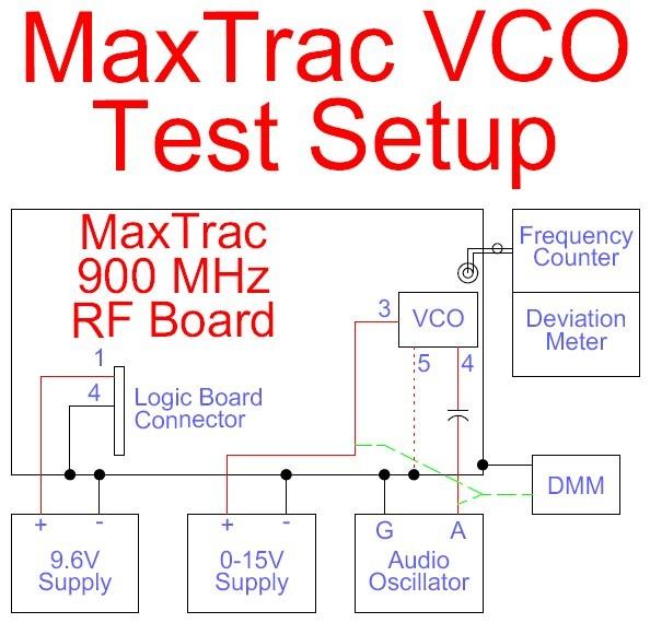
To gather data about the VCO's frequency limits and span, I removed the RF board from a 900 MHz radio and hooked it up on the bench to several pieces of test equipment. The RF board was operated in transmit mode. Here's a diagram of the test setup:
I then varied the steering line voltage at the VCO and measured the output frequency. The graph below shows the results with the pin shift line (at the VCO) low and high:
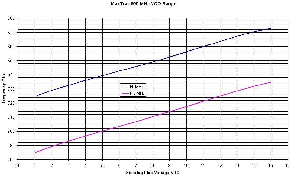
Note that the steering line voltage normally runs between about 2 and 7.5 volts, so the VCO's normal operating ranges (896-902 MHz and 935-941 MHz) are easily covered. However if the steering line voltage can be pushed higher, the VCO frequencies will readily go higher as well. The VCOs seem to change between 3 and 4 MHz per steering line volt. We require almost a 30 MHz range to cover the entire amateur band; this can be accomplished with a steering line voltage change of 8-10 volts. We can't run it lower than ground, but we can pull it higher than the available 9.6 volts by adding a source of 6-12 volts to the existing 9.6V. A well-regulated 15V supply will yield a solid steering line voltage range of about 2-13V. The important thing is that the frequency range can be easily pushed to over 30 MHz, which is enough to cover the entire amateur band, transmit and receive, with either half of the VCO. In fact, it allows us to use the left VCO for all receive frequencies and use the right VCO for all transmit frequencies. The modification to do this will also be covered.
We still must adjust the VCO's operating frequencies to move both sides down. The left side of the VCO operates as low as about 880 MHz; if we want to receive 902-928 MHz it needs to run 39 MHz lower, from 863 to 891 MHz MHz. Similarly, the right side of the VCO operates as low as about 930 MHz; if we want to transmit from 902-928 MHz it needs to run at those frequencies.
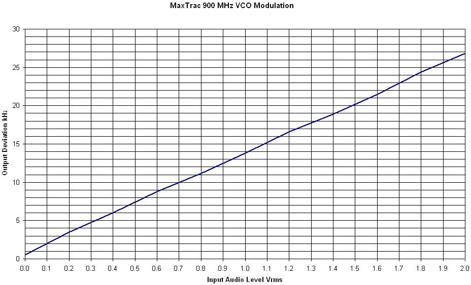
Previous tests on a 900 MHz MaxTrac show that the modulating audio being fed to the VCO is at a constant level regardless of the operating frequency. Circuitry on the logic board adjusts the level in 16 operating bands (8 bands from 895.5-902.5 MHz and 8 bands from 934.4-941.5 MHz) so the resulting deviation is consistent as the operating frequency is selected. However, when operating outside these frequency ranges, the radio picks some random value to use for the deviation adjustment. The VCO itself is quite non-linear as far as the amount of deviation produced as a function of the operating frequency, which is why the radio provides 16 adjustment points across the two bands. Here's a graph showing the deviation with a constant audio modulating level:
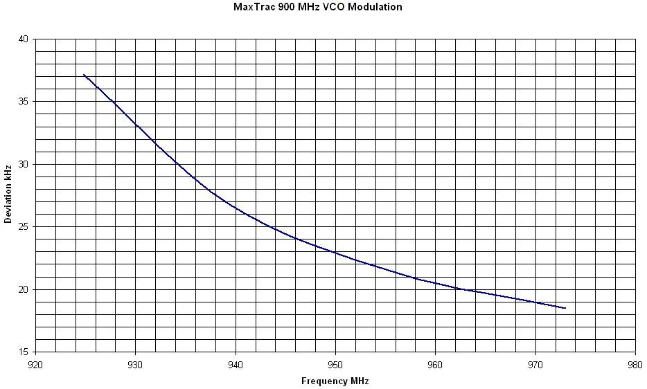
The 16 adjustment points increase the amount of audio going to the VCO as the operating frequency is increased. There isn't much change over either the 896-902 MHz or the 935-941 MHz pieces of the band that the radio was designed to cover. If a manual deviation pot is added to the logic board, the audio sent to the VCO will be a constant level, but the transmitted deviation will decrease as the frequency increases unless some kind of compensation circuit is added.
While we're working with the VCO, here's a graph showing the amount of deviation generated by the incoming audio. The service manual says 0.55Vp-p (about 0.2V) should generate 2.5 kHz of deviation. The graph shows a bit less audio was required on my VCO.
Getting 15V for the VCO:
So what can we do to get a higher steering line voltage? It needs to be well regulated, so we can't just take the incoming A+ voltage. The RF board only receives +9.6VDC from the logic board, and uses that to create its own +5V supplies locally using low-power three-terminal regulators, one for the reference oscillator and one for the synthesizer. My ground rules prohibit running a wire from outside the RF board, so I'm investigating any other method first.
A small DC-to-DC converter that would accept 9.6VDC input and give me 15VDC, regulated output would be perfect. But unless I want to spend hundreds of dollars, this just isn't economically feasible.
The next best solution is a small DC-to-DC converter that accepts 9.6VDC in and gives me 18-24VDC out, which I could feed into a low-power, three-terminal 15V regulator. But I was unable to find such a device. They typically only accept 5V or 12V as input.
There are several 5V to 12V DC-to-DC converter modules available. One of these should work if there is a sufficient supply of current. The steering line circuitry only needs about 20 mA, but these converters are, at best, 80% efficient. I doubt either one of the low-power regulators will be very happy with this much more current being drawn from it. These converters have isolated outputs, so I'll add it's output voltage to the existing 9.6V supply to get about 21VDC, which will then feed a low-power, three-terminal 15V regulator to operate the steering line circuitry.
I could run an NE555 timer IC as an oscillator from the 9.6V supply, run the output through a voltage doubler to get about 19VDC, and regulate that with a three-terminal regulator, but the parts count and size is too much.
I've ordered parts to build the 9.6V -> 5V -> 12V (on top of 9.6V) -> 15V solution. The circuit is shown below:
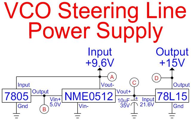
I built this first on a breadboard to test it out and measure things. I used a 750-ohm resistor as a 20mA load for the 15V supply (recall Ohm's Law: I = E / R), as this is supposed to be typical of the VCO circuit. I took voltage and current measurements at the circled points on the drawing; they are summarized below. Voltages are measured in AC or DC volts; currents are measured in DC amperes.
| Measurement / Point | A | B | C | D |
|---|---|---|---|---|
| No-Load DC Voltage | 9.57 | 5.02 | 27.48 | 14.94 |
| No-Load DC Current | 0.075 | --- | --- | 0.000 |
| Loaded DC Voltage | 9.51 | 5.01 | 21.95 | 14.93 |
| Loaded DC Current | 0.125 | 0.091 | 0.028 | 0.020 |
| Loaded AC Voltage | 0.011 | 0.007 | 0.009 | 0.000 |
Without the 10uF capacitor, the Loaded AC Voltage at point C was over 0.080 volts, and some of that came out at point D. Obviously the DC-to-DC converter has some unfiltered high-frequency noise coming out of it. The capacitor knocked it down to a reasonable level, under 1 millivolt. The resulting 15V DC supply is now very clean and stable. This will help reduce low-level noise modulation of the VCO.
The 0.091 amps of current at point B is very close to the maximum design rating of a low-power three-terminal regulator (0.100 amps with a proper heat sink), and even though the total dissipation is quite low (under 0.5 watts), I'm staying with the full-size LM7805 regulator. Besides, I can mount the LM7805 under one of the screws on the RF board and give it a more than adequate heat sink.
I made the modification to the RF board to accept a source of external 15 volts and connected the supply to it. Unfortunately, the radio was programmed with amateur frequencies and the VCO had been stripped of all its conductive paint, so the radio failed to operate as expected. The 15V supply, however, worked just fine. The current drawn from the external supply was within a few milliamps of what it was with the 750-ohm load resistor.
The next step is to solder these components together and actually integrate them into the radio's RF board.
Dealing with Pin Shift:
The pin shift signal (inter-board connector pin 14) is low to select the right VCO (for talk-around frequencies) and high to select the left VCO (for non-talk-around frequencies and receive). It gets inverted on the RF board to drive the VCO pin 5. There's also a transmit/receive signal (inter-board connector pin 4) that is low for transmit and high for receive. If we feed the pin shift signal from pin 4 instead of pin 14, the left VCO will be selected for receive (high) or transmit (low) rather than being frequency-specific.
It's not difficult to modify the RF board, but it's even harder to modify the logic board, so we'll choose the easier method.
On the RF board solder-side, make a small knife cut in the foil that leaves the bypass capacitor at pin 14 of the inter-board connector. Alternatively, if it's easier, cut the foil that runs between pin 14 and the bypass capacitor. Same effect: you're isolating the pin shift line (feeding the VCO) from the logic board. See the photo below.
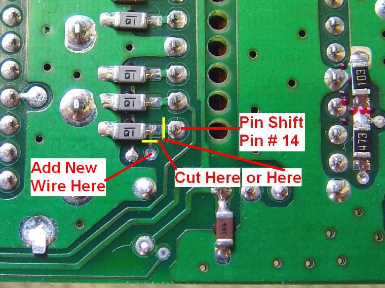
Run a small, insulated wire from the feed-through hole just below the cut you just made, up to pin 4 of the inter-board connector. There's plenty of room under the board for something as thick as #22 hookup wire. I used a piece of #30 wire-wrap wire. See the photo below. That's all it takes.
Attaching the New 15V Supply:
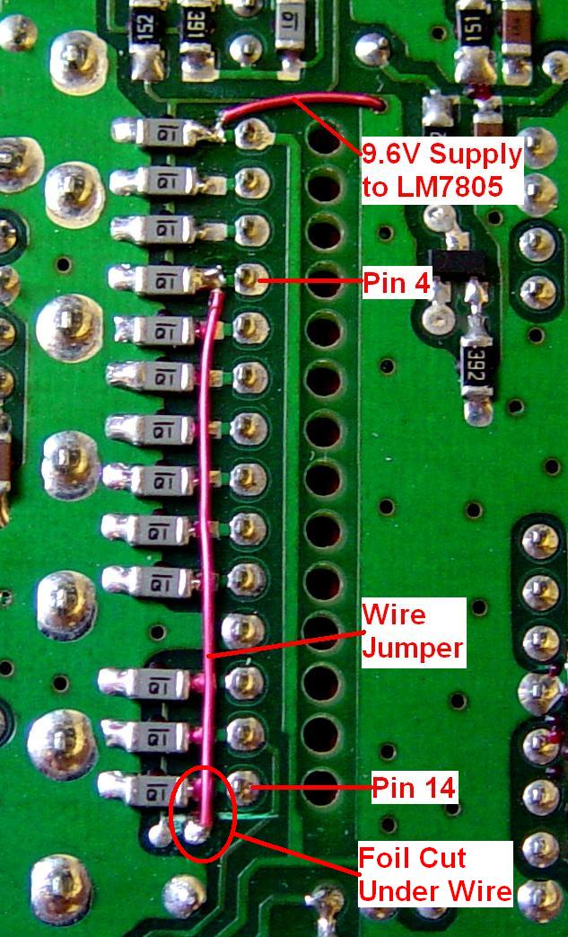
You need to disconnect the steering line circuitry from the existing 9.6V supply and provide it with the increased 15V from the components wired above. Refer to the photo below and make a cut in the visible area of the indicated foil.
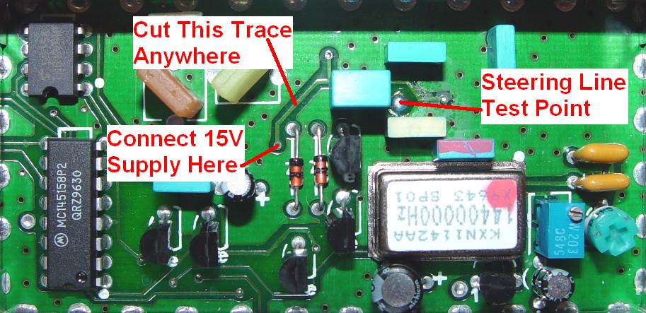
Attach your new 15V supply to the feed-through hole at the lower end of the foil you just cut. Depending on where you install your 15V supply components, you may need to run the DC wire through the VCO shield.
Here's a piece of the 900 MHz RF board schematic. The 9.6V line being cut feeds a 10-ohm resistor, R119. The new 15V supply feeds this resistor instead. See the annotated image below (click on the image for a larger view):

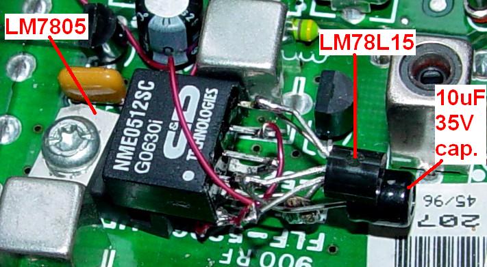
I built mine starting with the LM7805, which I mounted with one of the RF board screws. I ran a ground wire from underneath the board, up through one of the ground foil holes. I ran a piece of #30 wire-wrap wire from the inter-board connector pin 1 (+9.6V) through one of the ground foil holes, and up to the input of the LM7805. I used short pieces of wire or directly soldered the appropriate pins of the NME0512 to the ground, input, and output pins of the LM7805. I soldered the 10uF capacitor to the leads of the NME0512, then soldered the LM78L15 regulator to the ground and output pins of the NME0512. The last step was to connect the wire from the RF board steering line circuit to the output pin of the LM78L15. I finally mounted the RF board back into the radio's chassis. Here's a close-up of the finished assembly:
Adjusting the VCO:
There's already an article explaining how to make the 900 MHz VCO function for 25 MHz offset repeaters in the amateur band. Follow that procedure for the mechanical details then follow the next paragraph for the adjustment parameters.
Solder a short wire to the Steering Line (SL) test point, shown in the photo above, to make the measurements easier to do. Attach the positive lead of a digital voltmeter to this short wire and the negative lead to chassis ground. Connect a dummy load to the antenna jack. Program Mode 1 for 902 MHz transmit and receive, carrier squelch. Program Mode 2 for 928 MHz transmit and receive, carrier squelch. Turn the radio on and set it to mode 2. The SL voltage should be around 2 volts. Apply conductive ink to the left pad in the VCO and watch the voltmeter. Adjust the left (receive) side first, by adding enough ink to bring the SL voltage into the 11-12V range on 928 MHz, then switch to mode 1 and add or remove ink as necessary so the SL voltage is in the 2-4V range on 902 MHz. Check both extremes and make sure the SL voltage is between 2.5 and 12.5 volts on either mode. If the steering line voltage is too high or too low, the receiver will not open squelch, but if you open it manually (via the MON button), you will actually hear the signal. Verify that the receiver does in fact hear a signal at both frequencies. You'll need a lot more ink than in the above referenced article because you're lowering the operating range of each half of the VCO by about 39 MHz.
When I first wrote up and performed this procedure, I had programmed the radio for 900, 915, and 930 MHz, but I found that the VCO would not lock properly and the receiver would not open squelch at both 900 and 930 MHz. By making the band edges narrower - 902-928 MHz - the VCO locks and the steering line voltage is in the 2.5-12.5 volt range all the time. I could also have raised the supply voltage from a nominal 15 volts to something a bit higher. During my initial tests of the VCO, I ran the steering line by itself from 2 to 15 volts but the actual circuitry is unable to drive it higher than about 13.5 volts, and the radio isn't happy with it at those extremes anyway.
Repeat this process on the right (transmit) side, but key the radio to activate the right VCO (remember, we played with the pin shift signal earlier) as you'll have to make the radio transmit during these adjustments. Try for similar steering line voltage results. Check both extremes and make sure the SL voltage is between 2.5 and 12.5 volts on either mode. If the steering line voltage is too high or too low, the radio will refuse to transmit and it might make a "boooop" sound when you key it. Use a frequency counter to verify that the transmitter is operating on the programmed frequency.
Here are the steering line voltages I got at several frequencies before and after the VCO tuning procedure. Values are in DC volts measured at the SL test point:
| Mode | RX | TX | RX | TX | RX | TX |
|---|---|---|---|---|---|---|
| Freq. MHz | 902 | 902 | 915 | 915 | 928 | 938 |
| SL Before | 0.7 | 0.7 | 0.7 | 0.7 | 2.2 | 2.2 |
| SL After | 3.7 | 3.2 | 8.2 | 7.7 | 12.3 | 11.9 |
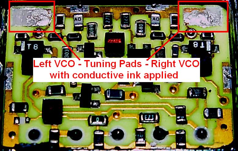
I used a brand new conductive ink pen for this project. The first bit of ink that came out was probably low in silver content; I put on way too much in an attempt to get the steering line voltage to come up. As it dried, the voltage went up way too far and I had to scrape an awful lot of it off. I will probably scrape it all off, squeeze a good large drop of ink onto something else, and take just a little bit of that over to the VCO and try it again. That's the nice thing about this method; if you go too far, it's easy to start over. The ink pen says it could take 10 minutes to dry, so apply a little dab, wait a while for it to dry, and add more if needed. To raise the steering line voltage, add more conductive ink; to lower it, scrape some off with a knife blade. While working on my radio, I always had too much ink on the solder pad and fine-tuned it by scraping some off from the outer edges towards the center of the VCO while the radio was operating (TX or RX). Be sure to remove all of the scrapings completely from the VCO. Here's a high-contrast photo showing the conductive ink on the tuning pads:
After I soldered the VCO cover back on, the steering line voltages increased by several volts on both transmit and receive, and the VCO would not lock or operate properly at 928 MHz. I had to remove the cover, scrape more conductive ink off the pads, realize I had gone too far, take it all off, put it back on, retune it after it dried, and solder the cover back on. I did this several times until I got the steering line voltages shown in the table above. The VCO got quite hot from the soldering gun, but I don't know why it didn't recover back to its earlier settings. At least the radio will never get this hot during normal operation, so I should be assured of reasonable VCO stability. The radio seems to work with any voltage between 2.5 and 12.5 volts, but the closer to 3 and 12 volts, the better. I surmise the LOCK signal isn't going all the way to ground at the extreme voltages, and the microprocessor prevents the radio from working under that condition.
Resulting Performance:
At all three frequencies listed above, the receiver breaks squelch at -130dBm and has a 20dB quieting sensitivity of -117dBm. Output power (manual power control) was set to 25 watts on 915 MHz and I got exactly the same level at 902 and 928 MHz.
Since only the span, and overall frequency range, of the VCO was changed, the modulation sensitivity is the same as it was before being modified. This means that the VCO's deviation level should be lower as the operating frequency increases. However, this was not the case on my radio and further investigation is warranted.
The deviation setting of the radio can range from 0 to 57. I set it to 0 and saved the value, then set it to 57 and saved the value, and finally set it to 28 and saved the value. This should have set the deviation for all 16 bands to the same number but I did not go through the full board replacement procedure to verify this. I later measured the actual DC voltage on U801 pin 6 of the digital-to-analog converter (DAC), which controls the deviation, and found it NOT constant; the values are in the table below. 902.0 to 902.5 MHz IS under control of the radio's firmware; the rest of the amateur band is NOT. The radio will find some value to use to set the deviation, just like it does for the transmitter output power. A manual deviation pot could be added to supply the Voltage-Controlled Amplifier rather than the DAC.
I fed a 400 Hz tone at 140mVAC (Low-level) into the MIC jack and measured the deviation at my three test frequencies. The results are tabulated below. Distortion was under 1%. I also fed in the same tone at 350mVAC (High-level), which caused some limiting/clipping to occur. The distortion rose, as expected, to 17%.
| Transmit Frequency |
Deviation Control |
Transmitter Deviation | |
|---|---|---|---|
| Low-level | High-level | ||
| 902 MHz | 4.2008 V | 0.975 kHz | 1.91 kHz |
| 915 MHz | 3.6070 V | 0.840 kHz | 1.61 kHz |
| 928 MHz | 3.6067 V | 0.940 kHz | 1.83 kHz |
With a 400 Hz modulating tone at 350mVAC (High-level) into the MIC jack, I varied the deviation setting with RSS and measured the DC voltage on U801 pin 6, as well as the overall deviation. All tests were done on 902.5 MHz, the frequency selected by RSS (luckily it was within lock range of the modified VCO).
| Pot | kHz | DCV |
|---|---|---|
| 0 | 1.0 | 0.37 |
| 8 | 1.2 | 1.22 |
| 18 | 1.4 | 2.70 |
| 28 | 1.9 | 4.19 |
| 38 | 2.4 | 5.69 |
| 48 | 3.2 | 7.18 |
| 57 | 4.1 | 8.50 |
I left the deviation setting at 40 (6.00 VDC), which gave me exactly 2.5 kHz of deviation. I replaced the tone oscillator with a base-station microphone and whistled into it loudly while measuring the deviation at my three test frequencies: on 902 MHz I got 2.76 kHz; on 915 MHz I got 2.46 kHz; on 928 MHz I got 2.70 kHz. This shows that a manual deviation pot might help keep the deviation more constant across the band. If the VCO still proves to be non-linear, at least the firmware deviation settings won't induce gross changes.
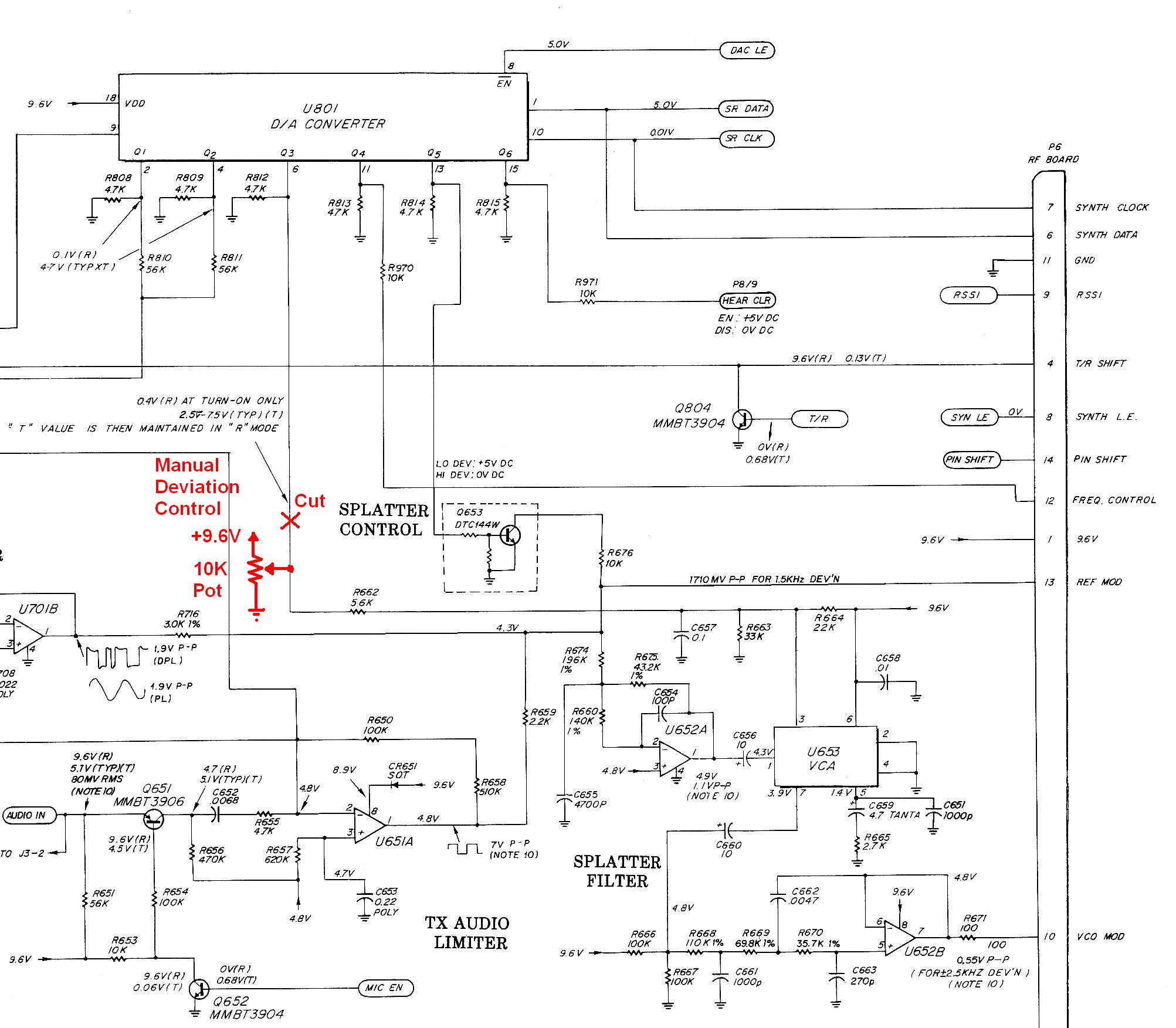
Here's a piece of the 900 MHz logic board schematic showing the transmit audio section and the location of U801 (click on the image for a larger view):
The parts cost about $10US total in mid-2007. Everything was bought from Mouser.
| Description | Part Number | Cost |
|---|---|---|
| LM7805CV 1A regulator | 511-L7805CV | 0.39 |
| NME0512SC DC-DC converter | 580-NME0512SC | 8.76 |
| LM78L15ACZ 0.1A regulator | 511-L78L15ACZ | 0.46 |
| 10uF, 35V aluminum capacitor | 140-L35V10-RC | 0.18 |
Here's a photo of the completely modified RF board (click on it for a larger view):
Manual Deviation Control:
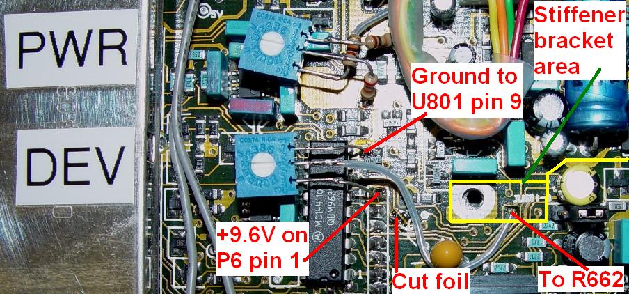
Naturally I was unhappy with the variations in deviation at my three test frequencies, so I made a cut in the foil leaving U801 pin 6 and added a 10k pot from +9.6V to ground with the arm feeding the rest of the circuit. Refer to the logic board transmit audio schematic shown in the previous section. The pot is a Bourns 3386X series that was bought at Mouser; their part number is 652-3386X-1-103LF (this is the same pot I use in the MaxTrac manual power control article - click on the link for more details). I mounted it with some Super Glue on top of two nearby blue capacitors to the left of U801. This provides a stable mounting surface but still allows the pot to be removed if necessary. The photo below shows the pot, the foil that was cut, and where the various wires go:
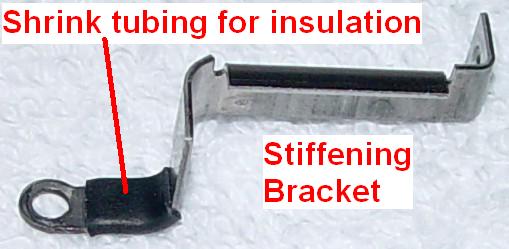
I tried to connect the arm of the pot to the remaining foil on the circuit board, but it was not strong enough. The next available feed-through hole was underneath the stiffening bracket. Even though I used Teflon tubing over the wire, I didn't trust it not to short out against the underside of the bracket, so I removed it and put a short piece of heat-shrink tubing as insulation over the area that covered the feed-through hole. (I have seen brackets that already have some foam padding under this area but mine didn't.) Here's a close-up of the insulated stiffening bracket:
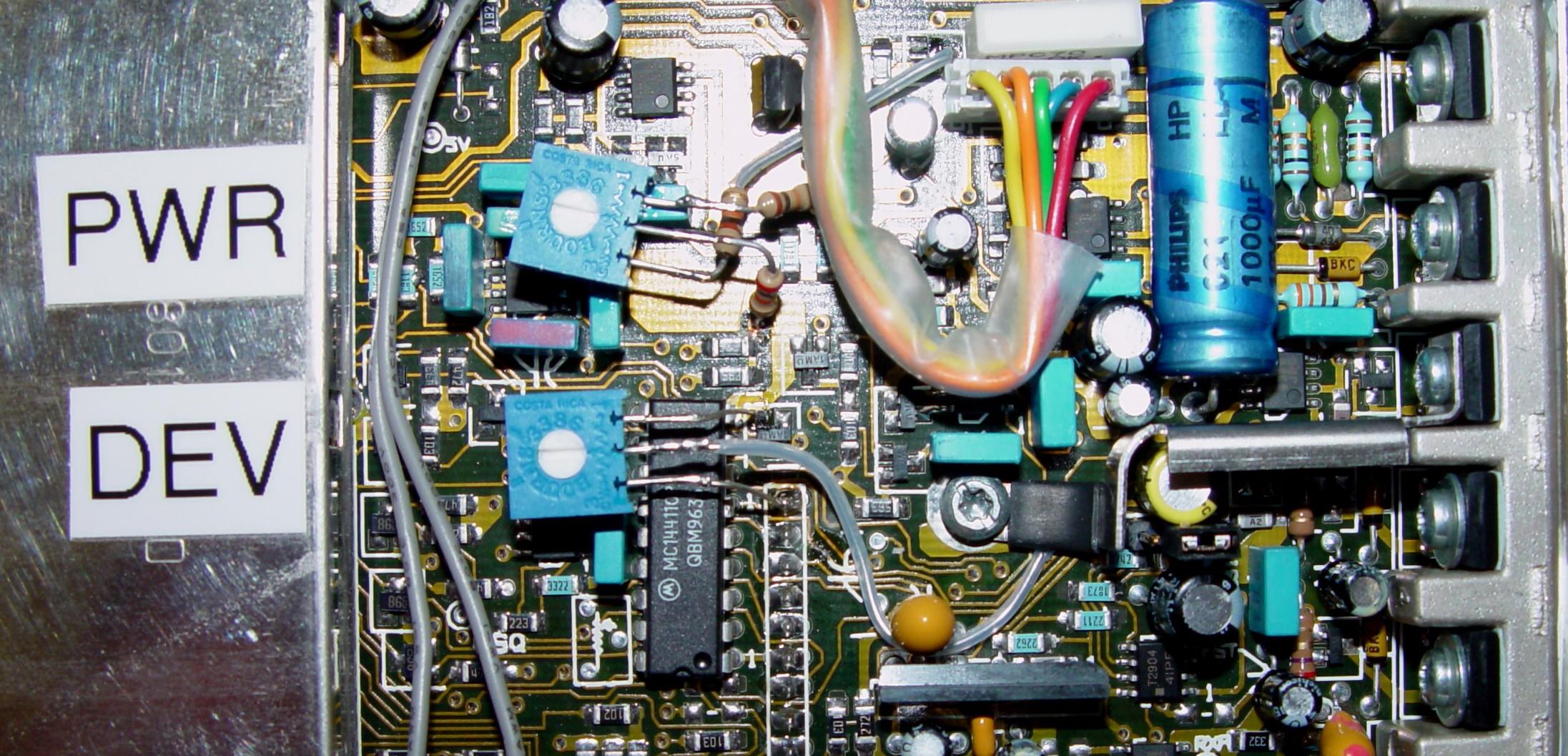
Here's a photo of the logic board with the stiffening bracket in place (click on the photo for a larger image):
So did this really fix anything? I fed 400 Hz at 350mVAC into the MIC jack of the radio (enough to cause some limiting) and measured the deviation of the radio operating on 902 MHz as I adjusted the DEV pot. The results are tabulated below:
| DCV | kHz |
|---|---|
| 0.0 | 1.05 |
| 1.0 | 1.20 |
| 2.0 | 1.37 |
| 3.0 | 1.57 |
| 4.0 | 1.85 |
| 5.0 | 2.18 |
| 6.0 | 2.57 |
| 7.0 | 3.11 |
| 8.0 | 3.79 |
| 9.0 | 4.50 |
| 9.6 | 5.00 |
With the pot set at 5.75V, I measured deviations of 2.47 kHz at 902 MHz, 2.27 kHz at 915 MHz, and 2.60 kHz at 928 MHz. So the overall deviation seems to hold constant within +/- 8% from one edge of the band to the other. I still don't know why it's so high at 928 MHz yet so much lower at 915 MHz, as this doesn't agree with my earlier findings.
I fed in a much bigger audio signal, 707mVAC, still at 400 Hz. I readjusted the deviation pot to 4.63V and got the same deviation levels as above. This is where I've left it.
Equipment Used:
Acknowledgements and Credits:
The NME0512 DC-DC converter documentation was obtained from the manufacturer's web site. Click here for the 600kB PDF data sheet for the NME-series parts.
Documentation for the 7805 three-terminal voltage regulator was obtained from the manufacturer's web site. Click here for the 250kB PDF data sheet for the LM78XX parts.
The 78L15 low-power, three-terminal voltage regulator documentation was obtained from the manufacturer's web site. Click here for the 75kB PDF data sheet for the LM78LXX parts.
Circuit information was extracted from the Motorola MaxTrac 100/300 Conventional 12-watt 900 MHz Service Manual, p/n 6802980G40, no longer available from Motorola.
Documentation for the Voltage-Controlled Amplifier (U653) used on the MaxTrac logic boards to control transmitter deviation, is hard to find. Click here for the 60kB PDF data sheet for the AN5262N part.
All photos taken by the author and are copyright by him.
Mike WA6ILQ gave me valuable corrections and suggestions.
Contact Information:
The author can be contacted at: his-callsign [ at ] comcast [ dot ] net.
Back to the top of the page
Up one level (MaxTrac index)
Up two levels (Motorola index)
Back to Home
This page originally posted on Monday 16-Jul-2007
Article text, photos, artistic layout, and hand-coded HTML © Copyright 2007 by Robert W. Meister WA1MIK.
This web page, this web site, the information presented in and on its pages and in these modifications and conversions is © Copyrighted 1995 and (date of last update) by Kevin Custer W3KKC and multiple originating authors. All Rights Reserved, including that of paper and web publication elsewhere.