Back to Home
Power Supply Information
HPN1007, TPN1136A, TPN1144A, TPN1154A, and VPN1013A
Schematic Diagrams and Load Tests
Provided by Eric Lemmon WB6FLY
Posted by Robert Meister WA1MIK

|
Motorola index Back to Home |
Motorola Desktop Power Supply Information HPN1007, TPN1136A, TPN1144A, TPN1154A, and VPN1013A Schematic Diagrams and Load Tests Provided by Eric Lemmon WB6FLY Posted by Robert Meister WA1MIK |
|
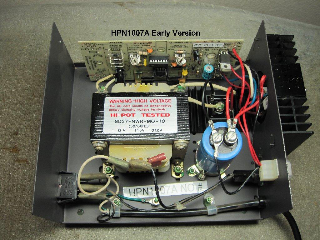
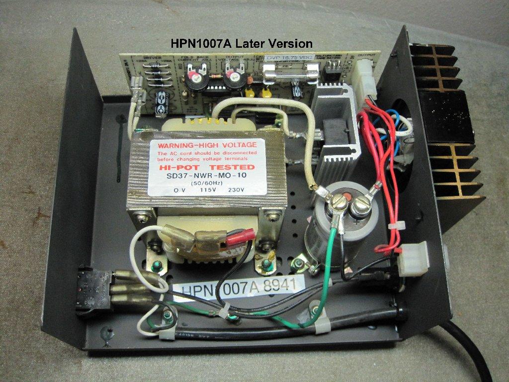
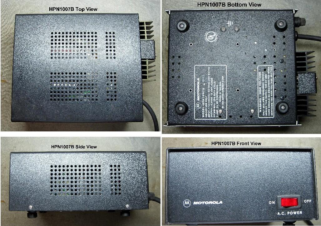
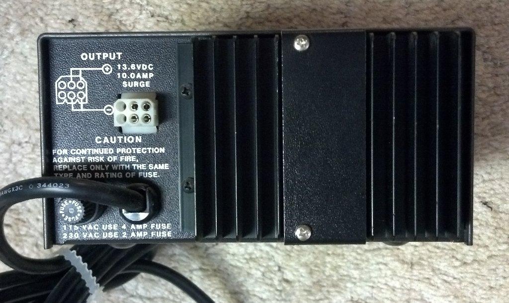
The HPN1007 power supply was intended to replace the HPN1004 and TPN1136A supplies to run low-power radios (2-15 watts), such as the Maxar and Moxy. It came in several issues. The early "A" version used a full-wave epoxy-potted rectifier; click here for an inside photo, while the later "A" version used two button diodes and a center-tapped winding; click here for an inside photo. All were made by Steed although they look very much like Astron units. Click here for a montage of outside photos. The "B" version was capable of a bit more power and they used pairs of contacts on the DC Output connector to handle that. Click here for a rear view. The supplies were certainly constructed a whole lot better than the Astrons of the day. Click here for an inside view.The load test report for the HPN1007A can be found here. The load test report for the HPN1007B can be found here. The schematics can be found below.
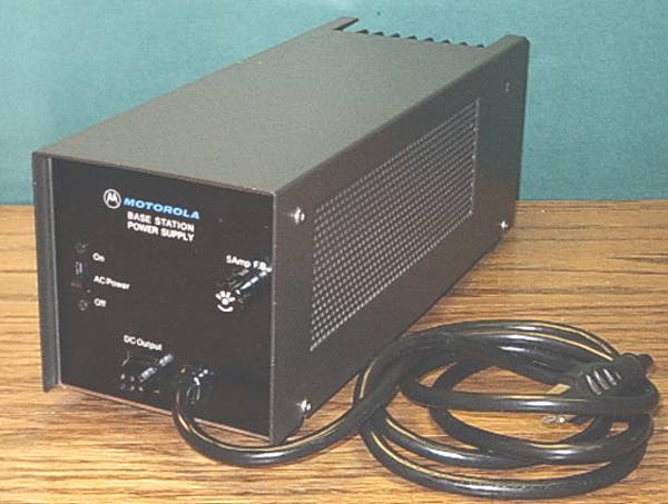
The TPN and VPN power supplies are very similar, but some have dual-voltage AC transformers and a 25,000 uF filter capacitor. The TPN1136A has a 120 VAC-only transformer and an 11,000 uF filter capacitor. Curiously, some stock TPN1136A power supplies have two M9244 pass transistors in parallel, even though the schematic diagram shows only a single M9639 pass transistor.
I ran a load test on my TPN1136A power supply, and found that it can carry over 17 Amperes - if the AC Mains fuse is increased in rating. With the specified 2A fuse in place, the supply can deliver about 7.5 Amperes. The load test report is available as a short PDF file here.
I ran a load test on my TPN1144A power supply. The load test report is available as a short PDF file here.
I finally acquired a working TPN1154A power supply, and confirmed that it is both electrically and physically identical to the HPN3000A power supply whose schematic diagram can be found below. They share the same transformer, rectifier bridge, filter capacitor, regulator board, and output pass transistors. As manufactured, the output voltage is fixed at just below 15 VDC, but adding a 5.6 kohm resistor in parallel with R7 will reduce the output to about 13.9 VDC. A photo of this unit can be found here.
I ran a load test on this unit. The power supply can provide 20 Amperes before the rating of the AC mains fuse (5A fast blow) is exceeded. However, the emitter ballast resistors used to equalize the currents in the two pass transistors are each rated at 7 watts, so the load should not exceed 16.7 Amperes or the resistors will be overloaded. The load test report is available as a short PDF file here.
For those readers who want to vary the output voltage of a TPN1136A or TPN1154A power supply, note that the VPN1013A power supply schematic shows a 500-ohm pot (R9) that was added to vary the base bias of the Reference Amplifier transistor Q2.
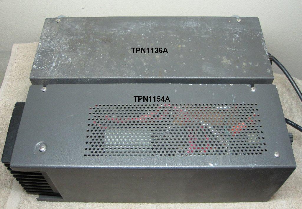
The TPN1136 and TPN1154 power supplies look very similar. If the label on yours has been removed, here are some items you can check to help determine which one you have.
| Feature | TPN1136 | TPN1154 |
|---|---|---|
| AC Fuse | 2A slow-blow | 5A fast-blow |
| Cover Cutout | None | Open over heat sink |
| Cover Screws | 4 | 8 |
| Heat Sink | 1 Transistor * | 2 Transistors |
| Ventilation Holes | No | Yes |
| Weight | 11.7 lbs | 17.2 lbs |
NOTE: The early TPN1136 supplies had two M9244 transistors in parallel; the later supplies had just one M9639 transistor.
There are also more fins on the TPN1154A heat sink. For comparison, here's a photo of the sides of the two supplies and here's a photo of the rear of the two supplies.
A summary of the DC output current amps and AC fuse rating amps is shown below.
| Model | DCA | Fuse |
|---|---|---|
| HPN1004 | 5 | 2 |
| TPN1136A | 7.5 | 2 |
| HPN1007A | 5 | 2 |
| HPN1007B | 5 | 2 |
| HPN3000A | 16 | 5 |
| TPN1144A | 25 | 8 |
| TPN1154A | 16 | 5 |
| VPN1013A | 16 | 5 |
Eric has written a short tutorial that explains how he performs his load testing. It also has some other useful information about power supplies in general. Click here to view this small PDF file.
The schematic for the HPN1007A power supply (earlier version) is available as a small PDF file here.
The schematic for the HPN1007A power supply (later version) is available as a small PDF file here.
The schematic for the HPN1007B power supply is available as a small PDF file here.
The schematic for the HPN3000A power supply is available as a small PDF file here.
The schematic for the TPN1136A power supply (earlier version) is available as a small PDF file here.
The schematic for the TPN1136A power supply (later version) is available as a small PDF file here.
The schematic for the TPN1154A power supply is available as a small PDF file here.
The schematic for the VPN1013A power supply is available as a small PDF file here.
Credits and Acknowledgements:
These PDF files were obtained from MAXAR, MCX100, and MCX1000 service manuals. They were posted in the Repeater-Builder Yahoo Group Files section on or around 14-Feb-11 by Eric Lemmon WB6FLY. They were retrieved by Scott KBØNLY. Bob WA1MIK formatted the text as an HTML article and posted everything on the Repeater-Builder web site. The HPN1007 schematics were drawn by Eric Lemmon WB6FLY.
Back to the top of the page
Up one level (Motorola index)
Back to Home
This page originally posted on Saturday 14-Feb-2011.
This web page, this web site, the information presented in and on its pages and in these modifications and conversions is © Copyrighted 1995 and (date of last update) by Kevin Custer W3KKC and multiple originating authors. All Rights Reserved, including that of paper and web publication elsewhere.