Originally Compiled and HTML'd by Mike Morris WA6ILQ.
Formerly Maintained by Robert Meister WA1MIK (SK).
Currently Maintained by Mike Morris WA6ILQ.
Click here or on the logo above for the main Icom USA web site
| Back to Home |
Technical Information on Originally Compiled and HTML'd by Mike Morris WA6ILQ. Formerly Maintained by Robert Meister WA1MIK (SK). Currently Maintained by Mike Morris WA6ILQ. Click here or on the logo above for the main Icom USA web site |
| Contact information: | |||||
| West Coast Office: Icom America Inc. 12421 Willows Road NE Kirkland, WA 98034, U.S.A. Tel : 800-USA-ICOM (800-872-4266) Fax : (425) 454-1509 E-mail : sales@icomamerica.com |
|
East Coast Office: Icom America Inc. 17000 Commerce Parkway Suite B Mount Laurel, NJ 08054 Tel : 800-USA-ICOM (800-872-4266) E-mail : sales@icomamerica.com |
|
Icom Canada Glenwood Centre #150 6165 Highway 17A Delta, B.C. V4K5B8, Canada Tel : (604) 952-4266 Fax : (604) 952-0090 E-mail : info@icomcanada.com |
|
FAKE ICOM RADIOS
Icom Japan has a fake radio problem. (off-site pointer opens in a new browser tab)
ALL Icom radios are produced in Japan. If you find an Icom radio labeled "Made in (any other country)" they are 100% fake (note that some legitimate accessories are not made in Japan). There are chinese and other manufacturers that are producing counterfit copies of Icom radios. If you suspect that you have been offered, or you purchased counterfeit Icom products, please contact Icom directly: export //at// icom //dot// co //dot// jp More details are available at the above linked page.
| Quick Jump to: | Programming Cables Modifications and Articles | |
|
Manuals, Brochures and Information | ||
| Quick Jump to: | Antennas Mobiles and Handhelds Handheld Batteries and Chargers Amateur Radio Repeaters LMR Repeaters |
Programming Cables
|
|
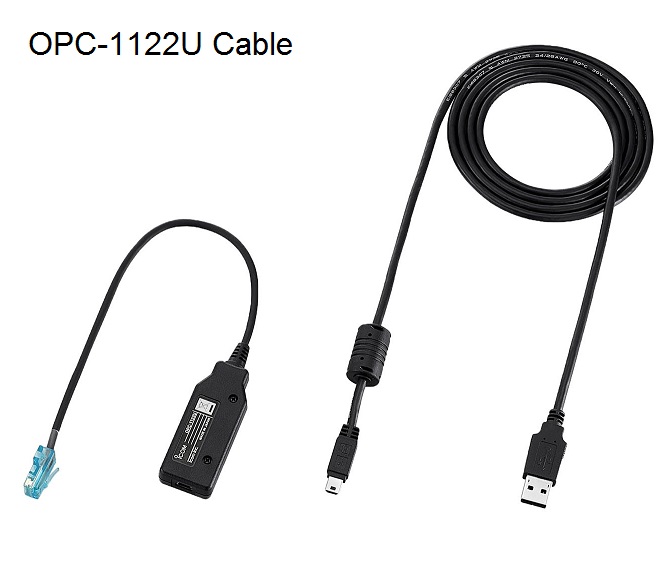
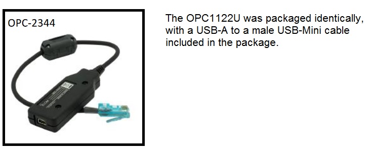
A lot of the Icom literature refers to their radio programming software as "cloning" software. Icom has a number of different programming cables and the official part numbers all start with an "OPC-" or "OPC-i" prefix. Some sellers market them without the hyphen, the "i" or both. And some manufacturers used OPC programming cables rather than producing their own. Years ago the author of this page had a Radio Shack scanner that arrived with a OPC-478 cable in the box. The radio shop that your author helps out at one or two days a week has a number of Icom factory cables that are serial port (DE-9 based) and a number of factory USB cables but the shop tends to use aftermarket FTDI USB cables due to past USB driver issues. Icom ships a USB driver CD with every factory cable and the shop has had driver clashes between the Windows drivers and the Icom drivers, and sometimes between two different Icom drivers.
|
|
|
Some Thoughts on Radio Programming Computers and Laptops by Mike Morris WA6ILQ This article is an opinion piece… What works for him may or may not work for you… His needs may align with your needs or may not. This article describes what the author uses and why… If you do a lot of field or bench radio or repeater controller programming you might want to consider dedicating a computer (especially a laptop) to radio programming. The author prefers the Panasonic CF‑30 / CF‑31 series Toughbooks for all of his field and bench radio programming because they are Mil-Spec rugged, configurable, parts are available, they are easily repairable with mimimal tools and have a 9-pin hardware COM port that always works. His CF‑30 runs 32-bit Win7 and the CF‑31 runs 64-bit Win10. Plus he can boot either Toughbook into MS-DOS with a thumb / flash drive for the older radios that use MS-DOS based programming software. The used Toughbooks are also a helluva deal - he has two rugged laptops that were each over $4000 new in his hands and fully operational with max RAM and a new hard drive for under $300 each. The aftermarket 9-pin serial OPC-478 cable that he uses is still sold, less expensive and can be found here. Most people will probably find the FTDI USB version to be more useful and that is here (both are off-site pointers and both open in a new browser tab) |
Modifications and Articles
|
|
UX-49 PLL Lock Fix (The UHF IC-900 module) By Kevin Custer W3KKC |
|
|
CTCSS Tone Chart By Kevin Custer W3KKC |
|
|
IC-2A/AT/E Frequency Range Mod |
|
|
A Modification for the IC-02, 03, 04 transmit audio (will probably be appropriate for the H16, U16 as well) |
|
|
IC-02, 03, 04, H16, U16 Tone Squelch encode/decode board information Donated by Jeff Kincaid W6JK |
|
|
Fixing the random microphonic crackle in the IC-2100 2m mobile |
|
|
Interfacing an IC-28, 38 or 48 mobile for remote base service Donated by Lee N3APP |
|
|
Some modification info for the IC-37 family.
Collected by Mike Morris WA6ILQ The IC-37 is the 220 MHz radio. Some of the info will apply to the IC-27 (2m) and IC-47 (440 MHz) versions. |
|
|
The IC-38 is a wonderful 220 MHz monoband radio and has a very hot receiver. It does, however, have a firmware bug – it will not transmit a CTCSS tone on simplex. There is a work-around that resolves the problem: Create a new memory entry for your simplex channel but program it in repeat mode with the correct tone but with the repeat offset set to zero. You will have your simplex frequency with tone. |
|
|
Interfacing the IC-RPxx20 Repeater
to a Link-Comm RLC Controller 58 kB PDF file This writeup is from Link Communications and is frequency independent. This information was donated by Eric Struble. |
|
|
Interfacing the IC-RP1520
Repeater to a Computer Automation Technology Inc. Controller 105 kB PDF file While the title specifies the IC-RP1520 the information is frequency independent and should be applicable to any Icom repeater that has the 8-pin DIN female accessory connector on the rear panel. And the interfacing of the the Scom and the Arcom controllers is very similar to the CAT controller family. |
|
|
A repeater mod for the F121, F121S, F221, and F221S commercial radios 77 kB PDF file. Donated by Sean Smith VE6SAR. |
|
|
General Icom Commercial Equipment Information Donated by Thomas Reynolds KD7SGM. |
|
|
MDC-1200 Compatible Models
565 kB PDF file MDC is an audio FSK data burst based system that is used to identify mobile radios in the land mobile radio world. |
|
|
Solving antenna connector problems on Icom
handhelds: IC2/3/4AT, IC02/03/04AT series Donated by Mike Morris WA6ILQ (his first ever article, was published in a local club newsletter around 1981 or so, back when anyone could walk into or mail order from the Tektronix Company Store in Portland Oregon). |
|
|
Increasing the CTCSS level on the IC-706MKIIG transceiver By David Branson KCØLL. |
|
|
Tips on the ICOM IC-706MKIIG by Bob Gass N4FV |
|
|
Expanded Frequency Coverage on TX and RX for the Icom IC-W32AE |
|
|
UX-series Module Interfacing
Design Guide 600 kB PDF file By Joseph Haas KEØFF A comprehensive guide to the interface signals and protocols used in the IC-900 and IC-901 multi-band transceivers. This is still a work-in-progress and will be updated as time permits, culminating in a full mobile radio control unit. Additional info on the ACC FC-900 interface for the IC-900/901 can be found on the ACC Index page. |
|
|
OPC-478 Programming cable CAD files (ZIP) Supplied
By James Craswell WØVNE These files are the CAD files for a program cable used with ICOM products such as the IC-F4S series of UHF Radios. It also works with a wide variety of other radios. You need to download the CIRCAD program from http://www.circad.net/. The free demo version should allow you to print out the schematic and even print out a template to make a PCB. Or you can hand wire a board using Vector board. This is a clone of the OPC-478 cable. Hams who like Circad can get the full version, which allows you to make GERBER files to mass produce PCBS for $250 (1/4 the price of the retail version). You can email me at w0vne // at // yahoo // dot // com for the details of that but remember: you won't need the full version to make up this board. |
Manuals, Brochures and Information
The IC-F series, IC-U series, and IC-V series radios are commercial Land Mobile Radios (LMR).
The M-series are marine radios, the A-series are aircraft (AM modulation), the FR and UR-series are LMR repeaters and options.
|
|
Icom's own Antennas Page If you need an antenna for your handheld, look here. Also has some base station and specialty antennas. (off-site pointer, opens in a new browser tab) There is a second page for discontinued products that is linked at the bottom. |
|
|
The Icom
AH-7000 wideband discone (30 MHz to 1300 MHz)
(data sheet) looks suspiciously like a Diamond D-130J
(which is available from
Amazon)
except made with an "N" male connector on the supplied coax (which makes sense as Icom ham radios go up to the 1.2 GHz band) instead of a PL259. Discones are zero gain by nature, and lossy coax will kill your reception, and it get worse the higher in frequency you go. The discone reception is flat from 100 MHz and up, the disc element length determines the low frequency limit, this one is very poor below 100 MHz except for the vertical coil section which is sharply tuned to the very low end of 6 meters.
eHam Review. (the AH-7000 is no longer offered, Icom now sells the AH-8000 (100 MHz and up). (all four pointers are off-site, each opens in a new browser tab) Update: Diamond sells the D-130 version with the N connector as the D-130NJ. |
|
|
Icom Manuals Download Page Icom's own manual page (offsite link) |
|
|
IC-2AE (European) Instruction Manual less cover 717 kB PDF file |
|
|
IC-2A / AT / E
Instruction Manual 3.2 MB PDF file Includes ratings info for a bunch of battery packs, as well as descriptions of most of the IC-2A accessories. |
|
|
IC-2AT / E complete schematic 95 kB PDF file (European model, with touchtone pad and tone burst) |
|
|
IC-2A / AT / E Handheld Service Manual 5.2 MB PDF file |
|
|
IC-µ2A / AT / E
Handheld Service Manual 3.1 MB PDF file Note this is the "Micro" 2A / AT / E model. |
|
|
IC-3A / AT 220 MHz Handheld Instruction
Manual 2.9 MB PDF file Includes specifications on BP2/3/4/5 battery packs. |
|
|
IC-3A / AT 220 MHz Schematic and PCB Layout 1.4 MB PDF file |
|
|
Anybody have the IC3AT service manual? |
|
|
IC-3SAT 220 MHz Handheld Instruction Manual 3.3 MB PDF file |
|
|
IC-3SAT 220 MHz Handheld Instruction Manual 3.9 MB version (slightly better detail) |
|
|
IC-3SAT 220 MHz Service Manual 2.8 MB PDF file Includes UT-49, UT-50, UT-51 tone/DTMF options. |
|
|
IC-4A / AT / E
440 MHz Handheld Instruction Manual 601 kB PDF file Includes info for BP2/3/4/5 battery packs. |
|
|
Anybody have the service manual for the IC4AT ? |
|
|
IC-µ4A / AT / E
440 MHz Handheld Service Manual 3.1 MB PDF file Note this is the "Micro" 4A / AT / E model. Includes info on the UT-37 option. |
|
|
IC-02A / AT Handheld Instruction Manual 1.7 MB PDF file |
|
|
IC-02A / AT / E 2m Handheld Service Manual 2 MB PDF file |
|
|
IC-03AT 440 MHz Handheld Instruction
Manual 3.9 MB PDF file Also relevant to the 02AT and 04AT. |
|
|
IC-03AT 220 MHz Service Manual 2.5 MB PDF file |
|
|
IC-04A / AT / E 440 MHz Handheld Instruction Manual 1.6 MB PDF file |
|
|
IC-04A / AT / E 440 MHz Handheld Service Manual 2.4 MB PDF file |
|
|
IC-A2 Maintenance Manual
1.8 MB PDF file Note that this is an aircraft band handheld transceiver (AM modulation). |
|
|
IC-4GA / GAT / GE 440 MHz Service Manual 2.4 MB PDF file |
|
|
IC-12GAT / GE 1200 MHz Handheld Service Manual 2 MB PDF file |
|
|
IC-22U / IC-24E/G Mobile Instruction Manual 1.0 MB PDF file |
|
|
IC-24AT / IC-24ET dual band Handheld Instruction Manual 3.6 MB PDF file |
|
|
IC-32A / AT / E dual band Handheld Service Manual 2.8 MB PDF file |
|
|
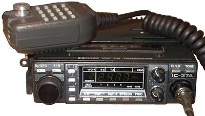
IC-37A 220 MHz Instruction Manual 2.6 MB PDF file radio photo |
|
|
IC-47A/E UHF Mobile Service Manual 2.9 MB PDF file |
|
|
IC-125 VHF Radio Telephone Instruction
Manual 1.2 MB PDF file A 5-channel diode-programmable transceiver that supposedly can be converted to operate in the amateur band by replacing two PLL crystals. Donated by Greg Beat. |
|
|
IC-125/T/TM VHF Land Mobile Radio Telephone
Maintenance Manual 6.5 MB PDF file The full service manual for the above radio. Donated by Greg Beat. |
|
|
IC-208H two band Mobile Instruction Manual 3.3 MB PDF file |
|
|
IC-208H two band Mobile Service
Manual 4.3 MB PDF file The service manual has a mis-print. On page 5-2 the resistor in the jig cable should be sized at 22 K ohm, not 2.2 K ohm. Even the Icom Knowledge Base Article on the topic has it wrong. You can download a fixed copy of the above file here as a 4 MB PDF file. |
|
|
IC-3200A/E dual band Mobile Service Manual 3.8 MB PDF file |
|
|
IC-3220A/E/H dual band Mobile Service Manual 2.7 MB PDF file |
|
|
IC-435 UHF mobile info package (sales flyer, schematic, programming) 2.1 MB ZIP file |
|
|
IC-706 Service Manual
4.4 MB PDF file Includes options UT-102 and AT-180. This is the HF radio that also does 6 meters. When coupled to a high-end repeater controller that understands what a HF remote base is (like an NHRC-10, an Arcom RC210 or similar capability controller) this makes a dandy HF remote base. Just watch the pre-emphasis and de-emphasis! Note that the Icom command language in the 706 microprocessor has a firmware bug: The 706 series will not let you set the VHF / UHF CTCSS encoder frequency from the serial port. There is a workaround for this that the NHRC-10 repeater / remote base controllers have as a built-in feature: you pre-program 32 (or whatever number you need) memory channels with the some dummy frequency (like 29.600, 52.525 or 146.520) and with the 32 (or whatever) CTCSS tones. Then to set the target frequency frequency just recall the appropriate tone-coded memory to the VFO dial (which sets the frequency and the tone), then change the dummy frequency to what you actually want to use. |
|
|
IC-706MKII Service Manual 3.5 MB PDF file This is the later 706 HF radio that also does 6 meters and 2 meters. The same firmware bug that affects the CTCSS frequency applies; use the same procedure. |
|
|
IC-706MKIIG User Manual
2.1 MB PDF file This is the most recent 706 HF radio that also does 6m, 2m and 440 MHz. I do not know if the CTCSS frequency firmware bug exists in this model, probably does. |
|
|
IC-706MKIIG Service Manual
12.7 MB PDF file This is the most recent 706 HF radio that also does 6m, 2m and 440 MHz. |
|
|
Don't overlook the IC-706MKIIG CTCSS deviation mod above - stock the radios had low CTCSS deviation, KCØLL fixed it. |
|
|
IC-756 Service Manual 6.5 MB PDF file |
|
|
IC-900A/E Mobile Service Manual 9.8 MB PDF file |
|
|
IC-901A/E Mobile Service
Manual 9.7 MB PDF file Includes options UT-40, UT-48, EX-766. |
|
|
IC-900-901A/E Data Structure 82 kB PDF file |
|
|
IC-2100H 2m Mobile Instruction Manual 790 kB PDF file |
|
|
IC-2100H 2m Mobile Service Manual 3.5 MB PDF file |
|
|
IC-2100H 2m mobile schematic package
2.4 MB PDF file Popular with the Packet / APRS community. Also see the IC-2100 modification file above. |
|
|
IC-7000 Service Manual 11 MB PDF file |
|
|
IC-F110S, 111S, 121S and IC-F210S,
211S and IC-F221S Service Manual 5.0 MB PDF file This contains two manuals: the first is the 8-channel 136-174 MHz VHF transceiver (pages 1-37) and the second is the 8-channel UHF transceiver (pages 38-74). The UHF model comes in two splits: 400-430 MHz and 440-490 MHz. |
|
|
IC-F111, 121 (VHF) and IC-F211, 221 (UHF) Instruction Manual 759 kB PDF file from Sean Smith VE6SAR |
|
|
IC-F111S, 121S (VHF) and IC-F211S, 221S (UHF) Instruction Manual 758 kB PDF file from Sean Smith VE6SAR |
|
|
IC-H16 and IC-U16 Owner's Manual 3.8 MB PDF file The owner's manual for the commercial version of the IC-02 and IC-04 (no programming info). |
|
|
IC-H16, IC-U2, and IC-U16 Instruction Manual 2.6 MB PDF file Seems to be a better scan of a different version of the above manual. |
|
|
IC-H16, IC-U16, IC-U2, IC-V100, IC-U400,
IC-V200, IC-U200 and the IC-V201 Programming information 1.8 MB PDF file Includes EX-494 programming keypad. |
|
|
IC-H16 VHF Handheld Service Manual
2.6 MB PDF file Includes schematics for CM7 and CM8 battery packs. |
|
|
IC-H16T VHF Handheld Service Manual
3.8 MB PDF file This is the later "T" version |
|
|
IC-H16 MK-II VHF Handheld Service
Manual 10.1 MB PDF file This is the later "Mark 2" version that was never imported into the USA. It's a totally different radio than the H16. |
|
|
IC-PS30 13.8V 25A Power Supply Instruction Manual 332 kB PDF file |
|
|
IC-R1 Wideband Handheld Receiver Instruction Manual
6 MB PDF file Includes info on BP-81/82/83/84/85/90 battery packs. |
|
|
IC-R10 Communications Receiver Instruction Manual 1.2 MB PDF file |
|
|
IC-R100 Communications Receiver Instruction Manual 2.2 MB PDF file |
|
|
IC-U16 UHF Handheld Service Manual
2.4 MB PDF file Includes schematics for CM7 and CM8 battery packs. |
|
|
IC-W2A / W2E Handheld
Service Manual 1.8 MB PDF file Includes option UT-63. |
|
|
IC-W2A / W2E Handheld schematics
only 514 kB PDF file To expand the receiver frequency range of the IC-W2A to 118.00-170.00, 322.00-513.00, and 800.000-970.000, do the following: Hold down the Light, B, and # keys while turning the power on. That's actually a four button sequence, since the power on function is controlled by a keypad button. |
|
|
IC-W21AT / ET Handheld Service Manual 4.2 MB PDF file |
|
|
IC-W31AT / ET Handheld Service Manual 2 MB PDF file |
|
|
IC-W32AT / ET
Handheld Instruction Manual 735 kB PDF file Includes info on BP170/171/172/173/180 battery packs. |
|
|
IC-W32AT / ET Handheld Service Manual 10.8 MB PDF file |
|
|
BC-35 Desktop Battery Charger Manual
with schematic 763 kB PDF file For BP2/3/4/5/7/8 battery packs. |
|
|
BC-35 Manual, a little
over half the size, no schematic 409 kB PDF file For BP/2/3/4/5/7/8 battery packs. |
|
|
BC-35 Schematic Diagram Vertically
oriented for printing 121 kB PDF file The BC-35 is the drop-in rapid charger for the ICM-5, IC-M11, IC-M16, IC-U16, IC-2GAT, IC-02AT, IC-2AT, IC-32AT, IC-4GAT, IC-04GAT, IC-04AT, IC-4AT, IC-12GAT, IC-03AT, IC-3AT, IC-IC-H2, IC-H6, IC-H12, IC-U12 plus the Radio Shack HTX202 and HTX404. |
|
|
Fixing a design bug in the BC-35 charger by Mike Morris WA6ILQ |
|
|
Data sheet on the rechargeable battery packs
for the IC-2/3/4 and IC-02/03/04 series handhelds 64 kB PDF file This data sheet covers the "amateur grade" BP-2, BP-3, BP-4, BP-5, BP-5A, BP-7, BP-8 and BP-70. Except for the BP-4 they are recharged in the BC-35 charger mentioned above (the BP-4 is a holder for ten AA penlight cells). |
|
|
Data sheet on the rechargeable battery packs
for the IC-H16, IC-U16 125 kB PDF file This data sheet covers the "commercial grade" CM-5, CM-7, CM-8, CM-12, CM-96 series. The trailing B (as in CM-7B) indicates black plastic, a trailing G (as in CM-7G) indicated gray. No trailing letter (as in CM-7) indicated dark gray. All except the CM-12 series are recharged in the BC-35 charger mentioned above (the CM-12 is a holder for ten AA penlight cells). |
|
|
CM-7 battery pack schematic (also
applicable to the BP-7) This is the high power ("12 volt") pack that has an interesting design - since the BC-35 is effectively an 11v charger designed to charge 9.6v batteries this battery pack uses an internal relay to switch two 6v cell groups in parallel for charging and in series (12v) for operation. |
|
|
CM-8 battery pack schematic (also applicable to the BP-8) |
|
|
RP-1210 10 watt 1200 MHz Repeater Service
Manual 6.5 MB PDF file The 1210 has a copper faced front and can only do a segment of the band, and changing the segment requires changing an internal crystal. |
|
|
RP-1220 10 watt 1200 MHz Repeater Instruction
Manual 1.6 MB PDF file The 1220 is the all black-faced unit and it does the full range. |
|
|
RP-1220 10 watt 1200 MHz Repeater Service Manual 4.7 MB PDF file |
|
|
RP-1510 25w VHF Repeater Operations
Manual 3.9 MB PDF file (older version) Includes DIP switch frequency setting chart. |
|
|
RP-1520 25w VHF Repeater Instruction Manual 3.8 MB PDF file |
|
|
RP-1520 25w VHF Repeater Service Manual 4.2 MB PDF file |
|
|
RP-1620 50w VHF Repeater Instruction Manual 2.1 MB PDF file (newer version) |
|
|
RP-2210 25w 220 MHz Repeater Operating and Service Manual 12.8 MB PDF file |
|
|
RP-2210 25w 220 MHz Repeater Operating
and Service Manual 5.1 MB PDF file A later version that's less than half the file size. |
|
|
RP-2210 220 MHz Repeater Frequency Switch Chart 35 kB XLS (Excel) format |
|
|
RP-4020 UHF Repeater Instruction Manual
1.7 MB PDF file Courtesy of Sam Skolfield KJ6QFS Note that the "service" manual below does not have any info on how to set the RF frequency and tone frequency DIP switches! This manual does! I suggest that you print the three pages of Section 4 and stuff it inside the repeater cabinet. |
|
|
RP-4020 UHF Repeater Service Manual
3 MB PDF file 10, 25 or 50 watts, depending on the model / version. |
|
|
RP-4520 UHF Repeater Service Manual
3 MB PDF file 10, 25 or 50 watts, 5 kHz or 2.5 kHz deviation depending on the model / version. |
|
|
UR-8050 UHF 45W Repeater Service Manual 650 KB PDF file |
|
|
Repeater EPROM Coding Information
43 KB PDF file donated by Skipp Has coding information for CW ID and various timers. |
|
|
ID-RP2010V / ID-RP4010V / ID-RP1200VD Repeater Instruction Manual 1.82 MB PDF file A local group asked me to research how to use one of these as a plain analog repeater with an external controller. This manual is useless for interfacing this repeater to an external controller… |
|
|
IC-RP2010V VHF Repeater Service Manual 33.5 MB PDF file Again, no mention of an external controller… and it's 144-148 MHz only. The local Civil Air Patrol group WAS interested in this unit for a few hours… |
|
|
ID-RP2010V / ID-RP4010V / ID-RP1200VD Settings Guide 3.1 MB PDF file Apparently this unit is designed for use only as a singe D-Star repeater or as a member of a D-Star cluster. I'd like to find out I was wrong. |
|
|
ID-RP2010V / ID-RP4010V / ID-RP1200VD Multiple Repeaters Addendum 5.8 MB PDF file Looks like doing anything but D-Star or in-cabinet analog / conventional repeat can't be done. |
|
|
FR-3000 / FR-4000 photo 177 KB This is a marketing photo of a tabletop model from the Icom web site, we'd appreciate a front and a rear photo of the rack mount version. |
|
|
FR3000 (VHF) / FR4000 (UHF) Series Brochure 234 KB PDF file |
|
|
FR3000 (UHF) Service Manual (dated July 2003) 8.1 MB PDF file |
|
|
FR4000 (UHF) Service Manual (dated July 2009) 16.42 MB PDF file This is just an addendum, anyone have the actual service manual for the FR-4000? |
|
|
FR4000 PA Replacement (dated 2008) 152 KB PDF file |
CY5000 / CY6000: (Uses the FR5000 / FR6000 module internally)
|
|
CY5000 / CY6000 Instruction Manual (dated 11-2009) 1.93 MB PDF file |
FR5000 / FR5300 / FR6000 / FR6300:
|
|
The FR5000 / 5300 covers 136-174 MHz in one frequency range.
The UHF FR6000 / 6300 are made in multiple ranges.
The range information appears on one of the screens of the programming software, and is encoded as
the last digit of the FCC ID number – it will be a 1 for low range and a 2 for high range. The first two digits
of the serial number also has that information: FR6000: 400-470 MHz: 01, 14, 41, 63 450-512 MHz: 11, 19, 51, 67 FR6300: 350-440 MHz: 22 or 62 400-470 MHz: 11, 12, 13, 17, 18, 51, 52, 53, 57 or 58 450-512 MHz: 31 or 71 450-520 MHz: 32, 34, 72 or 74 |
|
|
The FR-5000 / 5100 / 5300 / 6000 / 6100 / 6300 units use the OPC-1784 DC Power cable (Icom part number 8930017530).
This is the same power cable / connector as the IC-7100 / 7300 / IC-7400 / IC-7600 and IC-9700 HF radios and there are several aftermarket manufacturers of those power cables. Even Amazon has DC power cables for the that product line.
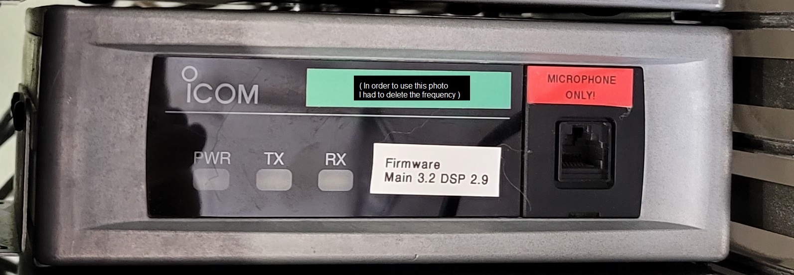
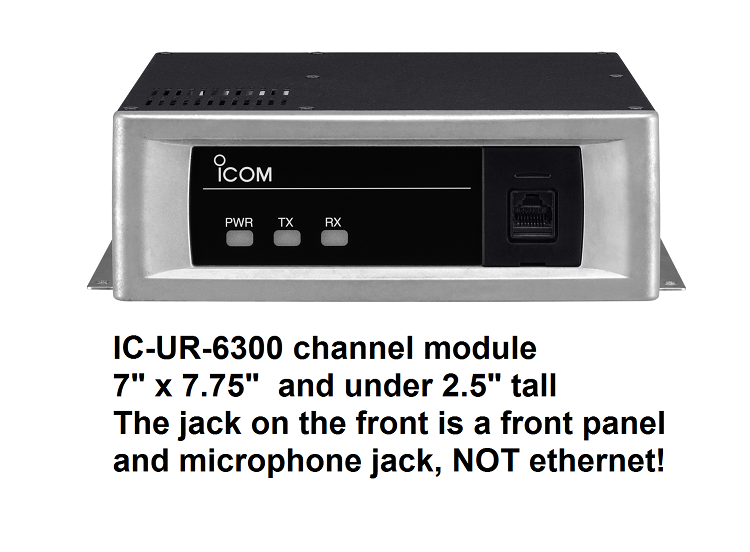
(note that the Icom uses a different part number for the amateur IC-7000, IC-7100, IC-7300 and IC-9700 DC power cable - it is OPC-2361, but it's the same. If you want to make your own DC power cable the radio end connector on the power cable and the pins are made by JST Sales America Inc. as the model VLP-04V (plug) and VLR04V (receptacle). Digikey carries the VLP-04V connector body (P=plug) and the SVT-61T P2.0 connector pins (you'll need 4). Or if you are like me you'll need 6 (you'll mangle a couple as you learn how to get the crimper to do the pins just right). If you damage the CAB-1116 power pigtail (the part hanging out the back of the "channel module", Icom part number 8920000830) the relvant part numbers are VLR04V connector body (R=receptacle) and the SVM-61T-P2.0 connector pins (again, you'll need 4). Thanks to Fred at Icom America support for the above information. Note: JST America is also the manufacturer of the 2-pin power connector used on the Kenwood TKR / NXR series repeaters and some of the TK-series and NX-series of LMR mobiles. Some of the material in this article will be of interest. (all of the above links are off-site pointers, each will open in a new browser tab) |
|
|
FR-5000 / 5300 / 6000 / 6300 Accessory Connector Pinout 378 KB PDF file This is the female DB-25 connector on the back of the module. Pin 20 is no connection on the FR5300 and FR6300 model. |
|
|
A brochure called an "FFB" - "Feature, Function, Benefit" by the marketing people 125 KB PDF This was a trade show handout. No tech info. |
|
|
FR5000 / FR6000 Product Brochure (dated 2018) 1.05 MB PDF file |
|
|
FR-5000 / FR-6000 Instruction Manual 570 KB PDF file |
|
|
FR-5000 / FR-5100 Service Manual 25.5 MB PDF file |
|
|
FR-5000 / FR-5100 Service Manual 3.61 MB PDF file |
|
|
FR-5000 Service Manual Addendums 8.34 MB PDF file |
|
|
FR-5000 / FR-6000 Configuration Guide 414 kB PDF file |
|
|
FR-5000 / FR-6000 Programming Guide 414 kB PDF file This is relevant to the FR-5100 / FR-6100 / FR-5200 / FR-6200 export models and the FR-5300 / FR-6300 second generation models. |
|
|
FR-6000 / FR-6100 Service Manual 9.6 MB PDF file Anybody have the manual for the FR-5000 / FR-5100 ? |
|
|
FR5300 / FR6300 Instruction Manual 1.2 MB PDF |
|
|
FR5300 / FR6300 Error Messages 121 KB PDF Also applies to the FR5000 / FR6000. |
Back to the top of the page
Back to Home
This page originally posted on 14-Oct-2004
Text, artistic layout and hand-coded HTML © Copyright 2004 and date of last update by Mike Morris WA6ILQ
This web page, this web site, the information presented in and on its pages and in these modifications and conversions is © Copyrighted 1995 and (date of last update) by Kevin Custer W3KKC and multiple originating authors. All Rights Reserved, including that of paper and web publication elsewhere.