Motorola Index
Back to Home
Compiled by Mike Morris WA6ILQ.
With thanks to Eric Lemmon WB6FLY for
his help on some chassis numbers
|
Mitrek Index Motorola Index Back to Home |
Decoding Mitrek Model and Chassis Numbers Compiled by Mike Morris WA6ILQ. With thanks to Eric Lemmon WB6FLY for his help on some chassis numbers |
|
Comments and additional material are welcome
(even "Hey - you've got a typo at..." messages)
In this article I'm attempting to help identify the model and chassis numbers of Mitreks that are good for both repeaters and for links. I've deliberately left out the 800 MHz and 900 MHz radios since I have no manuals or hands-on experience with them other than discovering that they are a single-channel-element-per-frequency design with an automatic and unchangeable 45 MHz offset between the receiver and transmitter (the IF frequency is the offset) and if I remember correctly they are repeater user radios only - they cannot do simplex.
This web page is intended to be use by folks that have some familiarity with Moto model numbers. All of the Motorola model numbers from the Mitrek and earlier vintages are in a standard predictable format that tells the frequency band, power level and options of the radio. Please see the general "Figuring out what you have" page linked off the main Motorola page for the basic info. I am going to assume that you are familiar with that web page as I continue here - all that is on this page is Mitrek-specific information.
The Motorola Mitrek series radios are very desirable for building repeaters and link radios despite the fact that the early versions are almost 20 years old...
As far as using a Mitrek in amateur repeat or link service, remember that the Mitrek mobile transmitter was not designed to be a 100% duty cycle transmitter. In fact, Motorola states in the manual that the Mitrek is a 20-25% duty cycle radio. This means that they were designed to transmit for no more than 20 to 25 seconds out of each 100 seconds. Mobile radios inherently have undersized heat sinks, so to keep the heat rise down make sure you keep the output power at no less than half of the rated output (the lower the better, but Mitreks get spectrally dirty and squirrely if run too low). Obviously the lower the power on the same sized heat sink means the low power ones are preferred for repeat / link service - even a low power radio at half power is enough to drive an external amplifier to whatever power level you can afford. And point-to-point links can use directional antennas... 5 watts into a 10 dB yagi gives the same performance as 50 watts into an omni with a lot less RF power involved, which means less DC power which means a smaller DC power supply and a lower AC power bill. The lower RF power also means you need less isolation in the antenna system, which translates into less spacing between receive and transmit antennas (or less duplexer) is required...
If you need a Mitrek manual please see this "How to Order Parts and Manuals" web page. The low band, high band and UHF radios are pretty much the same in the non-RF areas, but the RF sections are different enough that you can't do much if you don't have the right manual... (besides, you'll need the right manual when it comes time to tune it up)
As long as your are ordering manuals, you will want to order the
Mitrek tuning tool set, part number 6682977K01 (unless you have a huge
collection of diddle sticks - I have the standard 20-year collection that
fills a large wooden cigar box.... even a piano tuner's wand for doing
the old solenoid-tuned wide-spaced UHF Motracs). The real Mitrek
tool is (as of May of 2004) only $2.92 and breaking a slug with the wrong
tool is not worth three dollars.
(Update January 2006: It's now $4.20, still cheap compared to a cracked slug)
Personally, when I start playing with a new radio I buy two identical tuning tools. The first gets used, the seond gets placed in an envelope in the tool box (if it didn't come in an envelope I put it in one) with the radio name and the tuning tool part number on the envelope. When I break the first tool I unwrap the second and keep on going, but the empty envelope goes in the pocket that has the house keys. When I get home I reach into the pocket for the keys and find an instant reminder to order another tuning tool.
Unfortunately the "Mitrek Plus Supplement", part number is 6881046E05 no longer available (but it available for download). The Plus series, according to the manual's introduction, "is a mobile radio intended for use in critical applications. It is similar to the basic Mitrek radio with enhanced specifications in three categories, (1) reduced transmitter distortion, (2) increased receiver selectivity, (3) increased audio power output with reduced distortion." The first and second are definitely attractive to repeater and link operations in the amateur radio world..., the last makes sense in a public safety environment - you'd want to be able to hear and understand the dispatcher when you're going 90+mph with the siren going...
The additional selectivity comes from adding a 5th 2-pole crystal filter, labeled as Y204 on the main circuit board, physically right in front of L206. The main boards were apparently designed for it all along, the early radios had a jumper (J201) in place of it.
The additional audio power output comes from:
1) using different (more powerful) audio PA devices.
2) doubling the value of the two large electrolytic capacitors (physically
located on the interconnect board) in series with the speaker to 1,000uf.
3) using larger diameter speaker leads in the control cable.
4) a better speaker.
The reduced transmitter and receiver distortion is accomplished by a few component changes (interstage audio coupling capacitors, etc) and tuning with an audio distortion analyzer - the hardware is the same, the basic tuneup procedures are the same, they just do the fine tuning at the top of the peak or the bottom of the dip with the distortion analyzer. The old Heathkit distortion analyzers are on eBay all the time and you might want to consider picking one up. Get a manual also for the operational information... A lot of equipment can be used without reading the manual, an audio distortion analyzer fits into the area between "almost" and "not really".
There are no external markings on the Mitrek mobile chassis indicating a Plus configuration over the standard configuration - and if you don't know exactly where to look for Y204 - that extra crystal filter - on the main board then the Plus radios can only be identified by the chassis number. The presence of the 1,000uf capacitors on the interconnect board is not always indicative... I've found the larger caps on interconnect boards in radios that didn't have the additional crystal filter. More detais on the Mitrek chassis and model numbers web page and on the Mitrek Interfacing web page.
The "Plus Supplement" also notes that the Mitrek is an all-metric radio - don't casually mix the leftover screws into your parts bin.
A friend of mine told me that all the "Plus" changes were rolled into the manufacturing about the time the "B" series came out. I have no way to verify that.
| ||||||
Motorola made some Mitreks with a bulged top lid that either:
Motorola also made the "Super Consolette" - a tabletop base station that was available with either a low power or a high power 12vDC supply mounted internally. This base station had a regular mobile radio chassis mounted internally and that chassis was totally complete except for a missing model number / serial number tag. I have actually converted a 470 MHz base into a 52 MHz base in under 15 minutes by doing no more than pulling one radio chassis and mounting another. The consolette cabinet was essentially a pretty box containing an AC power supply chassis (and there were five different ones to chose from), the guts of a control head, plus some other options, such as a DC or tone remote, a battery-backup option on the internal power supply, channel-scan and a number of other options. However the radio chassis that Moto shipped inside the table-top base cabinets had different chassis numbers than the otherwise identical mobiles. Go figure - the only difference I can see is that the consolette chassis didn't have a model / serial tag - just a stamped chassis number where the tag would be. I've also seen full duplex Consolettes, and consolettes converted into desktop repeaters (there's a extra antenna jack hole aready punched and hidden behind a label, and enough room under the radio chassis for a flat-pack duplexer, or even a second radio chassis - as long as there is no wireline remote cards installed in that space).
More information on the Mitrek-based "Super Consolette" is at the consolette page.
NOTE: Out of a couple dozen units I have found two Super Consolettes that had a 10.8 MHz IF frequency! I don't know if this was a factory option that never made it into the manuals or if these were field converted (both came from locations that had two Consolettes side by side on a desktop or tabletop). The consolette book I have in my file cabinet does not list a 10.8 MHz IF as a factory option. If you suspect, even in the slightest, that your Mitrek chassis might have been a second station at a site at any point in it's career CHECK THE IF FREQUENCY before you order the receive crystals. Just check the part number on the side of any one of the IF crystal filters. There is a list of 10.7 MHz and 10.8 MHz IF filter part numbers in the Mitrek Interfacing writeup on this web site. My older eyes need a dental mirror and a magnifying glass to do that - your mileage may vary.
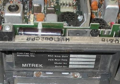
Motorola radios have two sets of identifying numbers: the model number and the chassis number. In the photo below you can faintly see the T44JJA-3000DK on the model number section of the nameplate and the HUE1082CPR chassis number stamped on the chassis lip. Yes, the "U" has a scratch through it and looks strange in the photo.
The low band book I have does not include the T71 models in it - they jump from T61 to T81. Yet I have seen Mitrek mobile radios with a T71 model label at two different hamfests, and the chassis number was that of a T81 model. Strange.
In the option code the extender option is available only in the low band radios. Other product lines (like the MICOR) had high band extenders, but the Mitrek didn't.
The rest of the option code digits are very specific to the product line. My Mitrek manuals list 000 and 900, and an email from VE1II provided the 800 code:
Bruce Harvey VE1II's email described some 12 frequency Mitreks that were made with a domed lid that held a board with the additional channel elements. The suffix on his radio is 1800B, with the "1" indicating carrier squelch, the 8 indicating 12 frequency, and the B indicating the chassis revision.
Except for the 12 frequency Mitrek mobiles the 000 and 900 means nothing as all the radios were the same internally. The 000 means that the radio was paired with a single frequency control group and the 900 means it was paired with a four-frequency control group. In other words the single frequency / multiple frequency difference was in the control head, the control cable (three extra wires), and the number of channel elements that were shipped with the radio.
The first letter of the option code suffix is the production line version or revision indicator. The Mitrek started with the A version and the first change bumped it to the B version. I have seen A, B, C and D version Mitrek low band radios, B version high band radios, and C, D and E version UHF radios. There are probably other versions out there. Every Mitrek Plus radio I have seen has a version codes greater than "B".
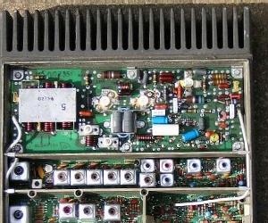
Mitrek chassis numbers are in the format of three or four letters, four digits and a letter. The first two or three letters in a Mitrek are always "HU" or "MHU". The next letter tells you the band. Next there are 4 digits that are the actual chassis number. The trailing letter tells you the chassis version. You will find the chassis number stamped in black ink just inside the radio on the top of the metal case rim above the latching handle and under the leading edge of the lid - see the photo at the beginning of this article. You will want to take a copy of the tables below with you when you go hamfesting... I personally have a copy in my Palm Pilot.
NOTE: I have no other information on any chassis numbers not listed below - everything below came from my Mitrek manuals or from contributed information. Missing information is marked with a "??". If anybody has additional chassis numbers to add, please send them to me but please include at least the model number, and a physical description (long chassis or short chassis, frequency range, 4-freq or 12-freq, with or without duplexer, with or without preamp, with or without extender (low band only), the TX power level, etc) - in other words, enough info that I can figure out what you have well enough that I can add it to the list.
Chassis numbers starting with:
If you have a MHUF / HUF chassis radio that has only one row of channel elements the odds are that you have a 800 MHz or 900 MHz radio (the elements will probably be number KXN1103A or B). I am not including any information on the those units below as I have no manual(s) on them. If anybody has a spare manual and wants to send it to me I'll write something up. At least xerox the model number and option tables and send them to me.
In the tables below "Reverse Engineered" numbers are those that appear in the field but are not in any manual. If you find one and can figure it out, send it in and I'll add it.
| VHF low band radio chassis numbers | |||||
| Chassis number | Frequency range MHz |
Power (watts) |
Extender option |
||
| Mitrek mobile |
Mitrek Plus mobile |
Consolette base * |
|||
| HUB1001B | HUB1043C | HUB1003C | 29.7 to 38.999 | 60 | No |
| HUB1011B | HUB1053C | HUB1013B | 29.7 to 38.999 | 110 | No |
| HUB1002B | HUB1044C | HUB1004B | 39-50 | 60 | No |
| HUB1012B | HUB1054C | HUB1014B | 39-50 | 110 | No |
| HUB1021B | HUB1063C | HUB1023B | 29.7 to 38.999 | 60 | Yes |
| HUB1022B | HUB1064C | HUB1024B | 39-50 | 60 | Yes |
| HUB1031B | HUB1073C | HUB1033B | 29.7 to 38.999 | 110 | Yes |
| HUB1032B | HUB1074C | HUB1034B | 39-50 | 110 | Yes |
| The early low band manual I have does not list any chassis with preamps - in fact the manual does not mention preamps at all. Like the UHF chassis list below, the chassis number would be different if the preamp was present. | |||||
| "Reverse engineered" low band chassis numbers | |||||
| Chassis number | Frequency range MHz |
Power (watts) |
Extender option |
RX preamp |
Information from |
| HUB1072C | 39-50 | 110 | Yes | No | Paul N1BUG |
| VHF high band radio chassis numbers | ||||
| Chassis number | Frequency range MHz |
Power (watts) |
||
| Mitrek mobile |
Mitrek Plus mobile |
Consolette base * |
||
| HUD1001B | HUD1053C | HUD1003B | 136-146 | 40 |
| HUD1002B | HUD1054C | HUD1004B | 146-174 | 40 |
| HUD1011B | HUD1063C | HUD1013B | 136-146 | 60 |
| HUD1012B | HUD1064C | HUD1014B | 146-174 | 60 |
| HUD1032B | HUD1074C | HUD1034B | 146-174 | 75/90/110 |
| HUD1031B | HUD1082C | ?? | 136-146 | 75/90/110 |
| As in the low band table above, the early high band manual I looked at does not list any chassis with preamps - in fact the manual does not mention preamps at all. The chassis number would be different if the preamp was present. | ||||
| "Reverse engineered" high band chassis numbers | |||||
| Chassis number | Frequency range MHz |
Power (watts) |
RX preamp |
Information from |
Additional Notes |
| HUD1052C | 146-174 | 40 | ?? | Eric Lemmon WB6FLY | Has the early front end casting, but has the extra crystal filter, larger speaker audio capacitors and machine-inserted jumpers (zero-ohm resistors). |
| UHF 403-420 MHz and 450-512 MHz radio chassis numbers | |||||
| Chassis number | Frequency range MHz |
Power (watts) |
RX preamp |
||
| Mitrek mobile |
Mitrek Plus mobile |
Consolette base * |
|||
| HUE1001B | HUE1071C or HUE1073C |
HUE1003B | 406-420 | 30 | No |
| HUE1005B | ?? | HUE1007B | 406-420 | 30 | Yes |
| HUE1002B | HUE1072C or HUE1074C |
HUE1004B | 450-470 | 30 | No |
| HUE1006B | ?? | HUE1008B | 450-470 | 30 | Yes |
| HUE1011B | HUE1081C or HUE1083C | HUE1013B | 406-420 | 50 | No |
| HUE1015B | ?? | HUE1017B | 406-420 | 50 | Yes |
| HUE1012B | HUE1082C or HUE1084C | HUE1014B | 450-470 | 50 | No |
| HUE1016B | ?? | HUE1018B | 450-470 | 50 | Yes |
| HUE1031B | HUE1116C or HUE1118C | ?? | 403-420 | 75/100 | ?? |
| HUE1032B | HUE1092C or HUE1094C | ?? | 450-470 | 75/100 | ?? |
| HUE1033B | HUE1093C or HUE1095C | ?? | 470-494 | 75/100 | ?? |
| HUE1147A | HUE1157B or HUE1159B |
?? | 470-512 | 30 | ?? |
| HUE1153A | HUE1161C or HUE1163C | ?? | 470-512 | 50 | ?? |
| HUE1156B or HUE1158B | ?? | 494-512 | 75/100 | ?? | |
| "Reverse engineered" UHF chassis numbers | |||||
| Chassis number | Frequency range MHz |
Power (watts) |
RX preamp |
Information from |
|
| HUE1082CPR | 460-470 | 50 | no | Eric Lemmon WB6FLY | Has the later front end casting, the extra crystal filter, larger speaker audio capacitors, and a timeout timer. |
Notes:
1) The Consolette base chassis numbers came from a revision "O"
manual. High band preamps and higher-numbered chassis were not in the
manual. Nor were they in the "O" high band mobile manual I looked in. The only
major difference between a consolette base chassis and a mobile chassis is that the consolette
base chassis seems to be missing the serial number tag.
2) The 75 and 100 watt high band chassis are the same. Only the setting of the power
output control is different. The same holds true for the 75, 90 and 110 watt UHF
radios.
3) The factory preamp was not that good - if your Mitrek didn't have one don't bother trying
to find one. An Anglelinear preamp is much,
much better.
For UHF amateur radio repeater purposes we are primarily interested in the 450 to 470 MHz range radios. The 406-420 MHz radios make good 420-430 MHz link radios, and are highly prized. Several folk I know are using Mitreks for link radios in the 420-440 MHz range of the UHF band. They report that most every 450-470 MHz Mitrek they've tried has had good receive and transmit performance as low as 435 MHz, sometimes 433 MHz. However if you are planning to use a Mitrek in the 420-430 MHz range you really need to look for a 406-420 MHz chassis. On the other hand the 470-494 MHz, 494-512 MHz and 470-512 MHz radios make pretty good doorstops, especially the high power ones.
One trick on determining the split of Mitreks:
Look at the top right of the photo below... see the number stamped on the inside
of the chassis (pointed to by the white line, next to the right edge of the
transmitter channel element)? That's the PA deck number... see below:
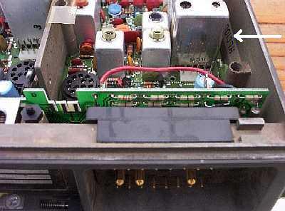
As mentioned above, if the last letter is a B, it's low band, a D it's high band, if
it's an E it's UHF.
Here's the entire list:
| Low Band PA Decks | |
|---|---|
| Low Power: | HLB1001 = 60w 29.7-38.999 MHz |
| HLB1002 = 60w 39-50 MHz | |
| High Power: | HLB1011 = 110w 29.7-38.999 MHz |
| HLB1012 = 110w 39-50 MHz | |
| High Band PA Decks | |
|---|---|
| Low Power: | HLD1001 = 40w 136-146 MHz |
| HLD1002 = 40w 146-174 MHz | |
| Medium Power: | HLD1011 = 60w 136-146 MHz |
| HLD1012 = 60w 146-174 MHz | |
| High power: | HLD1031 = 75/110w 136-146 MHz |
| HLD1032 = 75/110w 146-174 MHz | |
| UHF PA Decks | |
|---|---|
| Low Power: | HLE1001 = 30w 406-420 MHz |
| HLE1002 = 30w 450-512 MHz (in two different ranges of main boards - one for 450-470 and the other for 470-512) |
|
| Medium Power: | HLE1011 = 50w 406-420 |
| HLE1012 = 50w 450-512 MHz (again in two ranges) | |
| High power: | HLE1031 = 60w/75w/100w 406-420 MHz |
| HLE1032 = 60w/75w/100w 450-494 MHz (in two different ranges of main boards - one for 450-470 and the other for 470-494) |
|
| HLE1033 = 60w/75w/100w 494-512 MHz | |
When you buy your Mitreks, look for ones with the channel elements in them. These are little flat plug in aluminum modules that have the crystal and the oscillator circuit in them. If you have a choice be sure to grab a Plus radio (look for the later front end casting) with the elements in it! More info on this is on the Mitrek / MSR2000 Channel Elements page and on the Mitrek Interfacing web page.
Note that the channel element part number label and frequency label is one and the same. If it is missing, make sure you verify the channel element is operational in the band you want... I learned this the hard way - I once purchased a low-band Mitrek that came with a pair of UHF elements that had the frequency tags very carefully removed...
Good luck and after you get your Mitrek going please drop me an email and let me know how things went. Sometimes I wonder if anybody reads these missives to the masses...
Contact Information:
The author can be contacted at: his-callsign // at // repeater-builder // dot // com.
Back to the top of the page
Up one level
Back to Home
If you see something above that is vague, missing (or outright wrong), please let me know! It's input from the readers that make these writeups better - I've probably either totally missed or shortchanged topics and /or subtopics that really need to be covered.
Artistic layout and hand-coded HTML © Copyright 2005 and date of last update by Mike Morris WA6ILQ
This web site, and the information presented in and on its pages is © Copyrighted 1995 and (date of last update) by Kevin Custer W3KKC and multiple originating authors.