Up two levels
Back to Home
(of any type)
By Mike Morris WA6ILQ

|
Up one level Up two levels Back to Home |
Interfacing the Motorola Mitrek Mobile Radio To A Repeater Controller (of any type) By Mike Morris WA6ILQ |
|
Comments and additional material are welcome
(even "Hey - you've got a typo at..." messages...
Note: If you decide to print this file to put in your Mitrek manual make sure that the circuit diagrams below show up in a monospaced font (like Courier) if you want to see them properly. I used an exclamation point as a vertical line since the actual vertical line character (upper-case backslash on USA keyboards) is one of the first ones replaced by a local language character in non-USA keyboards and as a rule I try to make my writeups as international-compatible as possible.
This writeup, written in 2003, discusses how to modify any common Motorola Mitrek mobile two-way radio to add connections for a generic repeater controller - it does not matter if it's an NHRC, an Advanced Computer Communications (ACC), an S-Com, an ICS, a Link/RLC, a homebrew controller, or an IRLP computer interface board. These radio modifications are completely frequency independent - all they affect are receiver and transmitter audio connections and the control signals (push-to-talk, COR, PL decode, etc).
This modification set was originally developed by necessity for a dual UHF radio configuration (one radio for receive, the other for transmit) that implemented one end of a full duplex point-to-point link, but will work on any dual Mitrek configuration, a regular single Mitrek mobile radio, a duplexed Mitrek mobile, a tabletop base (Motorola marketing dubbed it the "Super Consolette"), a tabletop base converted into an intermittent duty low power repeater or a Mitrek used in mobile extender usage.
And here's the disclaimer.
The circuits and techniques described in this writeup worked for us and scratched our itch. As with everything in the hardware side of amateur radio (i.e. experimental electronics), someone else always has a better way of doing it. If you do, please cut and paste the appropriate section of this article text into an email, make your changes to it, and email it to us so we can update this web page with the better method.
I started this mod writeup as a set of handwritten notes on ruled notebook paper in the back of my Mitrek 3-ring binder as I read through the Mitrek manual. Then I got my hands on some surplus Mitreks, and Googled every mention of "Mitrek" and "modify" or "modification" or "repeater" or "remote base" on the internet and printed every article. Then using the schematics from the manual I reverse engineered every published mod to see what it did, and on some I tried them out - for example audio mods were tested using an Hewett Packard 200CD generator swept from 100 Hz to 5 kHz and an old Heathkit distortion analyzer. This writeup is the result of my experiments and experiences.
All of the work described here was done in a negative ground environment. The Mitrek mobile radio itself is designed for operation in either a negative or positive ground environment, but if you are using this info to help you build in a positve ground environment please realize that you are plowing a new field and are on your own. In all my years of working on commercial two-way radios I can count the number of positive ground installations I've been involved with on one hand and have multiple fingers left over.
The reason I used Mitreks in my system was that the Mitrek is an excellent performer, readily available, inexpensive at US$10 to $30 (because everybody wants synthesized radios like Maxtracs or GM300s where the Mitrek uses crystals - in fact it was the last crystal controlled mobile that Motorola made), and it is easy to work on (it uses through-hole components instead of surface mount). And if you do blow one up you are not out a lot of money.
I used dual radios in my point-to-point link since we wanted a full duplex link and you can't full duplex 406‑420 MHz Mitreks and keep them clean. My initial implementation used two 450‑470 MHz identical Mitreks tuned to the regular user input and output frequencies of the far-end repeater (443 MHz and 448 MHz), later replaced by Mitreks on real link frequencies (420.xxx one way and 439.xxx the other way... The 450 radios will make 439 easily, but not much below 435 (varies with the radio) so the 420 radios are required for the low end frequency of the link pair).
This is a "cafeteria collection" of radio modifications - you can pick and chose which ones you want to implement and no one mod is dependent on any other mod. If you are going to use two identical radios to implement a repeater or a full duplex link as we did in the beginning, I suggest you make the mods to both radios leaving half of each radio idle so that if something dies and you are in a bind you can simply find out what killed the radio, swap the two radio chassis and be back on the air, then at your leisure swap out the half-dead radio with a good spare. Note that this means that to implement your first one-way point-to-point link (with any radio - not just the Mitrek) you need to buy at least four radios... one for transmit from site #1, one for receive at site #2, one for a shelf spare, and one to blow up while getting familiar with the radio (and then to use for spare parts to keep the other three running). You can also make the same four radios a duplex link, as long as they aren't 406‑420 MHz Mitreks. If you are implementing your first Mitrek-based 420 MHz full duplex link you will need six... (a pair at the near end, a pair at the far end, a shelf spare and the sacrificial lamb...).
This writeup assumes a certain level of electronics and mechanical competence. It does not walk you through basic circuit construction techniques, how to add a 1:1 audio transfomer to prevent hum from a ground loop, how to solder, etc. The target audience for this writeup is a mid-level or higher repeater builder or maintenance person who is unfamiliar with the Mitrek radio and is adding one (or more) to his/her system, or exploring doing so.
In the "cafeteria collection" below there are schematics that show the interfacing components inside the radio because that's how I did mine. You can do it that way, or you can simply run the various signals to the connector pins directly and have the interfacing circuitry in its own box outside the radio housing. I mention this alternative because it was pointed out to me after this writeup was done that having the circuits outside allows one to have spare radios available with a lot less time spent inside each radio. And if someone wants to make up some blank PC boards for sale (or with all the interfacing circuitry preinstalled) I'll be glad to add a link / pointer to them on this page.
There is some deliberate repetition in this text - please excuse that as you read it, but since I wrote this document as a "cafeteria collection" a few things need to be mentioned in each relevant section. Even with this separation into individual modifications I recommend that you read this entire document all the way through at least once before you heat up the soldering iron.
Make sure that you have a correctly working radio, set up on the frequency of interest before you start the mods. Examine the radios carefully looking for leaky (physically) capacitors, etc. As Neil McKie WA6KLA (SK) once told me about repairs to remote base stations or repeaters, "better on the bench than at the site". You don't want to start modifying a radio, and when it's done discover it's not working, and you don't know if the problem is in the radio or the modifications. And if you are going to do multiple mods, test all functions of the radio after each mod is completed.
I guarantee that you will also find typos, and at no extra charge. A lot of these 65+ pages were done late at night after everyone else had gone to bed. I don't mind emails pointing them out, either. And to update one of my late fathers's old jokes, the new PC keyboard can't spell any better than the old one (he was licensed in Colorado at age 10 or so, let it lapse when he moved to Toronto, then relicensed in the late 1970s in Los Angeles as WB6SOX (my mom was WA6SOX)... he was an old time two-finger-typing newspaperman and a professional photographer for over 50 years... the original joke referred to when he upgraded his office from an Underwood mechanical typewriter to a Smith-Corona portable electric typewriter (complete with a power carrige return!) in the late 1960s and then again to a dual pitch IBM Selectric in the late 1970s. He used to joke that the new typewriter couldn't spell any better than the old one.
The modifications described in this document are generic and nothing in the repeater controller needs to be adapted to the radio, with one exception: if you plan on using the the stock Mitrek carrier squelch to drive the COR / COS / carrier detect line (the signal to the repeater controller) then the controller has to be able to mute the audio coming in from the receiver (the repeat audio)... the old ACC RC-series controllers couldn't do that - they relied on the receiver squelch circuit to do the audio muting or using the not-too-well-documented mod of installing an audio delay board and strapping its reset line to the COR signal. Both the Scom (now ICS) and Arcom audio delay boards were specifically designed to do the same trick in almost any controller, even an ACC. This article covers that situation. Yes, either the Arcom board or the Scom board (now sold by ICS) will replace the ACC delay board just fine. If you use the Link-Comm RLC-MOT board to add a MICOR squelch to the radio (highly recommended) then even this concern is eliminated.
The interfacing modifications and methods described here have been personally tested by the author on three different controllers. One of the test bed controllers was a home-brew Z80‑microprocessor-based unit, the second was a home-brew PIC processor, and the third was an Scom 7K. Emails have reported that this information has been used on several single simplex radios (used as remote bases), several duplexed radios (used as repeaters or as duplex point-to-point links), several dual radio combinations (used as point-to-point links) including the one described in this article, and at least two full duplex tabletop base stations (used as tabletop repeaters), and with controllers by Arcom, Creative Control, Computer Automation ("CAT"), Link (RLC-series), Pacific Research and NHRC, so I am confident that there are no hidden problems in these procedures.
Note that everyone who plans on using a Mitrek (especially UHF) in repeater or link service should read (and then re-read) the excellent Cactus Radio writeup on these radios located at http:// www.cactus-intertie.org/LA/tec_not5.pdf. In fact, click on it now and go read it and save a local copy.
I keep all of my Mitrek manuals in a 4-inch 3-ring binder and also included are documentation sheets on my mods plus printouts of various Mitrek related web pages. You should print the Cactus Radio writeup, read it, 3-hole punch it, and put it into → your ← Mitrek binder - it is a very well done writeup and is full of excellent technical info. There is one conflict between Cactus's writeup and what I have done here, they bring repeat audio out on the connector pin that I use for the PL decode logic level, but please read both sets of info and make your own choice on signal routing. If you have or are working on a UHF Mitrek I especially call your attention to page four of the Cactus writeup concerning the transmitter tuneup precedure and capacitor C‑800L (that's C-eight hundred-L). I lost two UHF transmitters before I discovered that quirk... So unplug the PA deck from the exciter before you start the tuneup. More on this later.
I recommend that you read this entire writeup completely (at least once). If you have already read through this and are returning to reference a certain section you can jump ahead to any section using these jump links:
These mods were developed using a pair of T34JJA 30 watt (low power) UHF Mitrek radios as test beds. The radios started out life as mobiles on a 464 MHz and 469 MHz commercial frequency pair (chassis numbers HUE1074C and HUE1082C). You can look up a chassis number or model number and see what it translates to on the model and chassis number lookup list. If you have a Mitrek chasssis number that is not listed there please send me full information so I can add it. Please don't email me asking about any chassis number not listed there - all the info I have is already up on the web page. Note that many of the Mitrek chassis are very similar - for example, the same high power chassis can have any of eight different chassis numbers depending on if the receiver preamp was factory installed or not, and if the output power control variable resistor was set to 60, 75, 90 or 100 / 110 watts during production line final test.
When I started this writeup I had low band, UHF and consolette (tabletop base station) manuals in the file cabinet, and before web-ifying this writeup I compared them to a friend's high band manual, mainly to make sure the component designators for the resistors, capacitors, jumpers, etcetera that I mention here were not different. Since these mods only affect the audio and squelch circuits they should transfer over to other bands (excluding 800 MHz as I have no manual) with no problems, but they have not been tried on actual low band or high band hardware (yet)
June 2003 update: I have since received emails from four different folks that have converted high band radios using this information and they state that everything matches).
Get a manual! I repeat - Get a manual! They
aren't expensive!
This document is complete as I can make it as far as how to connect a
Mitrek to a repeater controller, but is not a substitute for a real
manual - and you will need one anyway for the schematics, board
layouts (in color), and to tune up the radio. See
the Mitrek Index web page for a list
of manuals. You can call Motorola Parts at 800-422-4210 and
they will be happy to take your credit card or ATM card info and ship
you a manual. You can also watch eBay and the other auction web
sites for Mitrek manuals. Some are out of print, some are still available
from Motorola, at about US$30 each.
The Mitrek "Super Consolette" tabletop base radio has its own supplementary manual: 68‑81040E80. You don't need this manual to do any of the mods listed here, but if you end up with a tabletop Mitrek base it's very, very nice to have, especially if your unit has any options like DC (or AC) wireline remote control, VU meter, battery back up or channel scan (yes, Moto offered a scanning base station). Note that you also need the appropriate mobile manual (low band, high band, UHF, 800 MHz) to go along with it as the Mitrek tabletop base is simply a pretty black box that contains the power supply, the volume and squelch controls, the frequency switch, a speaker, a 1:1 audio transformer (between the Mitrek chassis and the speaker) and a mobile radio chassis. And if you find one with the higher power (i.e. the larger) power supply then you can run a low power tabletop repeater. The chassis even has a hole for a second antenna jack pre-punched (on some it's hidden behind a black caution label). This web page has more details on the "Super Consolette".
As long as your are ordering manuals, you will want to order the Mitrek tuning tool set, part number 66‑82977K01 (unless you have a huge collection of diddle sticks - I have the standard 20-year collection that fills a wooden cigar box.... even a piano tuner's wand for doing the old solenoid-tuned wide-spaced UHF Motracs). The real Mitrek tool is only US$2.92 (as of May 2004) and cracking or breaking a slug with the wrong tool (trust me - you WILL do that with a Radio Shack tuning tool) is not worth three dollars.
(Update: January 2006... It's now $4.20, still cheap compared to a cracked slug - and tuning tools break at the most inopportune times - I suggest that you order two, and keep the second in the wrapper in your kit. When you break #1, unwrap #2 and stuff the wrapper in your pocket, then use #2 to finish the job. When you get home and empty your pockets you will find the wrapper and that will remind you to order #3... or even #3 and #4.)
As long as you are ordering tuning tools, Moto came up with a Universal Tool later on. you will want to order the 6684387C01 Universal Tuning Tool from Motorola Parts (800-422-4210) at about $ 6.00 each. This tool is a "must have" for anyone working with GE or Motorola radios, since it has 0.075" and 0.100" hex on one end, and a thin steel blade on the other, which satisfies all tuning adjustments on MASTR II, Exec II, MVP. MICOR, Mitrek, MSR2000, etc., etc. It has a nice large gripping area for fine control. The only thing I have done to improve it is to add a piece of tape around the tool and stuck to itself to make a 1/4 inch long "flag". When the instructions call for "2 turns" or "3 and 1/2 turns" the flag makes it easy to hit the turns count exactly. Plus it keeps the tool from rolling off the bench.
The Mitrek Plus supplement is 68‑81046E05 and is definitely worth getting if you can get one... it includes the mods for using a Motrac / Motran / Mocom 70 control group with the Mitrek. Unfortunately the last time I called they were out of stock and not planning to reprint them. So we scanned one and put the PDF on the main Mitrek page.
For more information on manuals and how to order them, see the "How to order manuals or parts from Motorola" web page that can be reached from the main Motorola page. The "Figuring out what you have" page can also be useful.
Another note... the manuals are not consistent on the option boards: the UHF book that I have (68‑81045E75‑A) is the only Mitrek manual I have in my collection that has documentation on all three PL and DPL boards - the HLN4020 single or dual reed-type PL board, the HLN4181 "reedless" (also known as the "tone-element") PL board and the HLN4011 Digital PL (DPL) board. And the late UHF book - the 68‑81045E75‑B does not have the later HLN4181 (reedless) board in it! (at least my copy didn't). The 4181 schematic is downloadable from this web site.
The ‑A revision highband book I looked at does not have the HLN4020 reed-type board schematic. There may be a newer revision out there.
The ‑O original low-band book I have does not have the HLN4181 reedless PL board or the DPL board documentation. There may be a newer revision out there.
Note also that the Mitrek is an all-metric radio - don't casually mix the leftover screws into your parts bin.
Now I'm going to define some terms that I'll use in the rest of this writeup:
Lastly, be aware that the same jumper number can appear in multiple places - there can be a JU3, for example, on the main board, another JU3 on the interconnect board, a third JU3 on the PL board and maybe a fourth JU3 inside the control head. I've been very careful in this writeup to specify where a specific jumper is when I reference it, but keep this in mind, especially if you are reading someone elses writeup.
CAUTION: DON'T LET
THE SMOKE OUT !
The radios that preceeded the Mitrek in the Motorola mobile product
line mostly used push-pull audio PA decks and audio output transformers,
and drove the speakers as a hot wire to ground. The Mitreks, and
many later radios eliminated the audio transformer and they run the the
speaker as the push-pull load directly ... both sides floating off of
ground. This quirk is significant on your workbench: any audio
test equipment that connects to the speaker (such as you would use to
make a quieting measurement) must be on the far side of a 3.2 ohm
or 8 ohm 1:1 audio transformer. Motorola has a low-power
one as part number SLN6435 in their test equipment catalog (being "test
equipment", it's high priced at about $80), and they also include a
cheaper but higher audio power one in every tabletop base station (part
number 25‑80188B01, about $35 in late 2006) since common wireline
remote controls expect ground-referenced audio to drive the remote
sepakers. You can order either one as a spare part, or you can
get one from a web-based car stereo seller or at a local high-end car
stereo shop (many dash-mount radios expect floating speakers, and many
trunk mount audio amplifiers have gounded inputs). In a pinch
you can put a 2 watt resistor of any value from 8 to 16 ohms on the
radio as a load, and use a 600 ohm to 600 ohm line transformer between
the radio and the test equipment. Note that the audio bandpass
characteristics of that isolation transformer will have to be wider than
the audio frequencies you hope to pass through the radio.
In short, if you ground one of the Mitrek speaker leads, the odds are excellent that you will let some of the magic smoke out of your radio. So use an audio isolation transformer to prevent this - just put the transformer between the radio and any load that isn't an ungrounded stand-alone speaker. If you are looking to buy an audio isolation transformer, check put the car stereo shops in your area - sometimes they are marketed as "audio ground loop eliminators", or as "balanced to unbalanced adapters" - but look carefully as some of them are at 600 ohm impedance levels. Ideally you want one that is at 8 ohm levels at a watt or two of audio... (the audio level alone precludes using a transformer salvaged from a old modem or PC sound card). There are also ones designed to work at millivolt levels - they are a collection of resistors and capacitors. Always check the schematic - you want a transformer-based one that has no DC path from either input lead to either of the output leads. You may already have something that will work - if your junk box includes two identical audio transformers that have an 8 ohm secondary (no matter what the primary is, as long as both transformers are the same) then you can use the pair to make a single substitute 8 ohm to 8 ohm audio isolation transformer. Just tie the primaries together and use the secondaries of the two transformers as if they were one 8 ohm to 8 ohm transformer. And some times you can recycle something - the most flexible audio isolation transformer I ever found was an aircraft radio power transformer from the 1940s - the two separate 6.3 volt windings worked fine as 8 ohm windings, the 110/120 volt winding worked fine as a line level connection, and the 400 Hz design worked just fine from 250 Hz to over 3500 Hz.
Since a repeater or a point‑to‑point link is a single frequency beast the four frequency select leads plus the "SP" (spare) lead in the cable (pin 18 - the middle big pin) are available for reuse as input and output pins. Note that there is a 0.01 µf bypass capacitor between the F1 lead (pin 7) and ground (at C602). If you are going to reuse that pin, you might want to remove C602, depending on how you plan to use it. If you decide to yank it, look for it right next to the Frequency #1 transmit channel element. It's interesting that the F2, F3 and F4 lines do not have similar bypass caps.
There are two versions of the Mitrek: the early "Mitrek" and
the later "Mitrek Plus", however you can't tell which one you
have without looking at the radio's interior or looking at the
chassis number. The differences are fully documented in
the Mitrek Plus supplement manual I mentioned above and among
other things the "Plus" radios have a better front end physical
design, extra IF filtering and some filtering chokes on the control
cable pins. The Mitrek Plus really is the preferred radio
when you go hunting for Mitreks. Not that the original
Mitrek isn't a fine radio, just if you have the opportunity to
paw through a pile of radios it makes no sense not to pick the
better / nicer ones...
GENERALLY, the "A" series is the "Mitrek", the "C" and later are
"Plus", and somewhere in the "B" series the transition took place.
But look for the RCA plugs and the extra crystal filter first
(see later in this text).
To determine which version you have you will have to do one of the following:
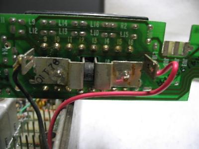
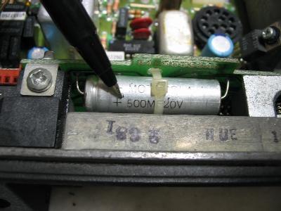
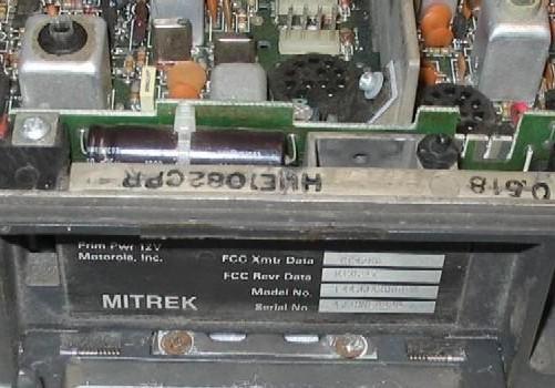 Photo 1: In this photo you can see the HUE1082CPR chassis number stamped on the front lip of the chassis. On this particular radio the "U" looks strange in the photo because it has a screwdriver scratch through it. |
 |
 |
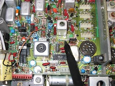 Photo 4: This is an early Mitrek and is shown without the PL board in place. The pen points to the jumper that replaces the filter (this is a carrier squelch radio - no PL board - note the red connector at the bottom left - that is where the PL board plugs in. And as mentioned elsewhere in this writeup, the red plastic body on the connector identifies the good / later plating.) |
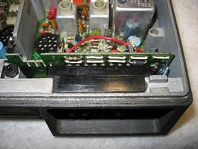
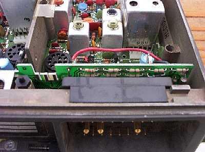
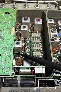 Photo 5: This is a later Mitrek Plus - the black pen points to the extra crystal filter - You want the radio(s) with the extra filter. If you need to add Y204 to a radio it's Moto part number 48‑84396K02. |
 |
 |
 |
 |
 The small board visible behind the interconnect board is the optional timeout timer. If you accidentally sit on the microphone it drops the PTT after 3-4 minutes and generates a really loud and obnoxious tone through the radio speaker for as long as the PTT button is depressed. |
The Bottom Line: If you have a choice when you select a radio, pick a Plus radio by the chassis numbers that are on the Mitrek Chassis and Model Numbers web page, but if you don't have that list with you (I have it in my Palm Pilot) by all means pick the radios first with the the RCA connectors on the front end / exciter filter assembly. The second item to look for is the Y204 extra IF crystal filter - but if it's not there is can be added easily.
Channel Elelements: Get at least one set of channel elements with each radio - and really, really try and get the original elements - and then test the radio using a dummy load and a calibrated signal generator before you make any modifications. You don't want to spend a lot of time converting a radio then find out it's dead, and you can't tell if the problem is in the original radio or in your conversion. If you can't get the original elements, then try and get ones that are close in frequency for testing and can later be recrystaled to your needs. Make sure that the elements you do get are the proper ones... one of my six meter radios came with UHF elements in it ‑ and I suspect the eBay seller obviously knew they were the wrong ones because he had carefully removed the element model number / frequency stickers. Note that the UHF GMRS service requires 0.0002% tolerance. If you end up acquiring an ex-GMRS radio you might want to put the high-accuracy elements aside for recrystalling on your repeater or link frequencies. And note that the crystals are cut differently between the 0.0002% and 0.0005% elements - a crystal cut for a 0.0005% element and mounted in a 0.0002% element will never get close to frequency (and vice versa).
The Mitrek and MSR-2000 use the same elements, as described on the Mitrek / MSR-2000 channel element page. You can change the crystals in the elements yourself, but it's better if you have the rock chippers do it. I suggest you read the article titled "Why should you really spend $50 to re-crystal a channel element or ICOM" on the Tech-Info page at this web site. While on the topic of crystals, the transmitter uses 12 MHz rocks (with a x3 multiplier on low band, a x12 multiplier on high band / VHF, and a x36 multiplier on 450 / UHF). The receiver uses 48 MHz rocks and low injection (on VHF the calculation is (channel frequency‑10.7 MHz)/3, on UHF replace the /3 with /9). Remember that like most Motorola radios in a Mitrek the first tripler is inside the channel element. I've used 30-year-old scanner crystals tack-soldered into a receive element for a simple bench receiver tuneup (it doesn't matter if the 146.76 MHz scanner crystal is more than 30 kHz off frequency when all you want to do is see if the receiver works or not), but never for permanent use. I've also used an element as a buffer for an RF signal generator to get a head-start on tuning a receiver from 460 MHz down to 439 MHz before the recrystalled channel elements arrived (don't forget to compensate for the tripler in the element... in most cases you will need to set the generator to 3 times the actual crystal frequency that it is replacing).
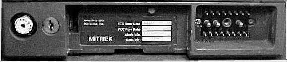 Photo 10: The front panel of a Mitrek mobile. Visible is the antenna connector, the mounting tray lock, the model/serial number tag and the control connector. Above the number tag is the spring-loaded top cover release, it looks like a nut driver would be used to turn it, but in reality it's a pushbutton. The key is the standard Motorola mobile radio key - a Chicago Lock and Key H2135. For more info on two-way radio keys visit the keys page. On the particular radio shown in the photo the fold-down handle is missing. |
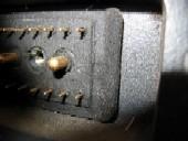 Photo 11: Don't be surprised if some radios have a foam gasket on the control connector. This was very common in dusty and humid areas. |
If you are picking radios and heads out of a pile to build a repeater or a single frequency link pick a single-frequency head with the monitor switch and be sure to pick out a multifrequency cable. Moto shipped one of four different cables with each Mitrek... a "single frequency" cable (that was missing condictors 6, 8, 9 and 10) and the "multi-frequency" cable with those and in high power or low power. The only difference between the low power and high power cables was the diameter / gauge of the big red and black wires to the battery). When you go looking for cables look for white, grey, blue and black wires (labeled on the control head end with the numbers). Also make sure that you have a pin 18 - it is a black-grey wire.
By the way, you will want to print the jumper table below and stuff it into your Mitrek manual as I've never seen anything listing the interconnect board jumpers in ANY of the Mitrek manuals I've seen, even on Moto's schematic of the interconnect board (the ones I have show no jumpers or chokes, just direct connections). I put this list of jumpers together as I traced out the interconnect board as I modified my link radios.
|
||||||||||||||||||||||||||||||||||||||||||||||||||||||||||||||||||||||||||||||||||||||||||||||||||||||||||||||||||||||||
A note on control cables...
A lot of Mitreks were installed in 18-wheel trucks. Some of those
control cables end up on the surplus market wired for positive gound. Because
manufacturers (Mack, Kenworth, Peterbilt, etc.) had not standardized the
polarity of their tractors when the Mitrek was introduced, it was common for
Mitrek cables to be modified in the field from negative to positive ground
use. As a result, part numbers stamped or printed on cable assemblies
may not correctly reflect the polarity for which they have been wired. It
is best to refer to the factory negative ground versus positive ground cable
diagram in the manual BEFORE you touch that used cable. (thanks to KI4BQQ for the
reminder)
Power Connections:
In a normal mobile installation pin 19 is hooked to the positive
side of the vehicle battery through a large diameter cable and a
big fuse - and the fuse is usually placed under the hood near the
battery. Both constant and ignition switched power
is run to the control head via relatively small wires (#18 or #20 ga). In
a normal mobile installation the always-hot green wire on pin 19
allows the receiver to be run with the ignition key off, and the
switched DC on pin 20 requires the key to be on to enable the
transmitter.
Normal mobile installation:
                                     thick wire
Pos --- Big Fuse ----------------------------------------------------- Pin 19 of
12v     Amperage depends on                                            the control
        the transmitter power                                          connector
        level of the radio.                                             (big pin)
        See the manual for                                             (PA deck +V)
        the value.

Battery                               thick wire
Gnd ------------------------------------------------------------------ Pin 17 (big pin)


                                       inside the control head
                                       !---------------------!
                                       !                     !
                                    control                  !
Local                                head                    !
Gnd --------------------------------Pin 17                   !
(local to the                          !                     !
control head)                          !                     !
                                       !           /         !
Constant +12 from                   control       /         control     control
underdash fuse box                  head         /!         head        connector
(e.g. the battery  ---- 7A fuse ----pin 19 -----O !  O---+--Pin 4 ------Pin 4
side of the clock                      !          !      !   !          (receiver power)
fuse)                                  !          !    J O   !
                                       !          !    U !   !
                                       !          !    1 !   !
                                       !          !/   0 !   !
Switched +12 from                   control       /    1 O  control     control
underdash fuse box                  head         /       !  head        connector
(e.g. the battery  ---- 7A fuse ----pin 20 -----O    O---+--Pin 12 -----Pin 12
side of the broadcast                  !    double pole      !          (transmit enable)
radio fuse)                            !    power switch     !
                                       !   (part of the      !
                                       !   volume control)   !
If you choose to use a control head there is an already-existing jumper (JU101) option inside the head (left open by default) that shorts pin 4 to pin 12. If you use JU101 you can ignore control head pin 20.
If you are not going to use a control head (for example, mounting the radio on a rack panel, with the controls mounted to the rack panel or in in the lid of the radio), or if you want very simple wiring, we can consolidate and simplify the power wiring as per the schematic below (using the power switch on the power supply as the on/off switch):
                        thick wire       Control connector
Pos --+-- Big Fuse ----------------------Pin 19 (PA deck and transmitter)
12v   !
      !                 thin wire
      +- 5a or 7a fuse ---+--------------Pin 4 (receiver power)
                          !
             thin wire--> !
                          !
                       \  O  This transmit enable switch can be installed in the
                        \    body of the control head if you like. Find the pads
                         \   labeled JU101 on the control head PCB and use them
                          O   for the switch.
                          !
                          !  However keep reading - there is a better way to do
                          !  it: short JU101 (or jumper pin 12 to pin 4) and
                          !  relocate this switch in series with pin 13
                          !  (PTT) - this is shown later on in the PTT section.
                          !
                          +-------------------Pin 12 (transmit enable)

                                      +-------Pin 6 (frequency select logic)
                                      !
                         thin wire--> !
     thick power wire                 !
Gnd ----------------------------------+-------Pin 17 (radio ground)
The size (amperage) of the big fuse depends on the band and power level of the radio and is covered in the Mitrek manual. By the way, the receiver and transmitter enable pins (pin 4 and pin 12) draw very little current.
The size of the wire you will need for the "thick wire" connections above is dependent on the current flow and some basic electrical theory. Large diameter cables have less resistance, and E=IR. Low current means the voltage dropped across the power supply cables is minimal. Now when you keep the same power supply cable in the circuit (R remains constant), and you attempt to transmit (draw lots of current through the battery cable) the E (the voltage) dropped across the cable goes up and the voltage at the transmitter goes down. The transmitter (not just the Mitrek - any mobile radio) does not like low voltage at all. It gets squirreley if it works at all. Basically, for a low power radio (T2xJJA, T3xJJA or T4xJJA model numbers) the smallest you want to use is 12 gauge wire, and 10 gauge for any higher power radio (the T5xJJA, T6xJJA, T7xJJA, T8xJJA series). Use the next larger size wire for any run over 10-12 feet. You want a minimum of 13 volts DC across pins 17 and 19 of the radio while under full load.
Some folk run the hot side of the 7a fuse to pin 19... I don't like to do that because if the big fuse blows for some reason it will kill the receiver as well. You can run the 7a fuse either to the positive 12v directly or through the big fuse, whatever works easier for you. In my case I was dedicating an Astron power supply to this double-radio assembly plus I was using a control head so I added a large in-line fuseholder for the PA deck power (radio pin 19) plus a small fuseholder for everything else. I put both of the fuse holders in the cable harness that coupled both radios to the control head and the power supply. A diagram of the power wiring is later on in this writeup.
Control Head Connections, and how to make it work without one...
If you are not using a control head you can connect your own speaker, volume and squelch controls as follows (don't forget to ground the Frequency 1 channel element pin inside the radio - read further on for notes on JU611 - look for "Duplex mods for the Mitrek"):
        interconnect board and ! control !
        control connector      !  cable  ! control head
       !-----------------------!---------+------------------+
       !                       !         !                  !
        +!!C1
radio ---!!----------Pin 3 ----------------pin 3--+--Pin 29--
main     !!                                (in)   !  (out)     \
board                          !         !        !            to speaker
                               !         !        +--Pin 31    note that both
                               !         !           (out)     sides are hot!
        +!!C2                                                 /
radio ---!!----------Pin 5 ----------------Pin 5-----Pin 32--
main     !!                                 (in)     (out)
board                          !         !

radio---------JU13---Pin 15 ---------------Pin 15-------------------+
main          L15    Volume                on head                  !
board                wiper     !         !                          !
                               !         !                          !
        +!!C3                                                       !
radio----!!---JU10---Pin 11 ---------------Pin 11---+-----+         !
main     !!   L11    Buffered              on head  !     !         !
board                audio out !         !          !     !         !
                  (unsquelched)!         !          \     \         !
                               !         !    3.3k  /     / 10k     !
                               !         !    1/4w  \     \ 1/4w    !
                               !         !     or   /     /  or     !
                               !         !    1/2w  !     ! 1/2w    !
                               !         !          !     !         !
                               !         !          !     !         !
                               !         ! 25k pot  \     \ 25k pot !
                               !         ! Squelch  /     / Volume  !
                                                    \     \         !
radio---------JU12---Pin 14 ---------------Pin 14-> /     / <-------+
main          L14    Squelch               on head  \     \
board                wiper     !         !          !     !
                               !         !          !     !
                               !         !          !     \ For this
                               !         !          !     / resistor
                               !         !          !     \ see text
                               !         !          !     / below
                               !         !          !     !
                               !         !          !     !
radio----------------Pin 2-----------------Pin 21---+-----+----------Pin 27--+
main                 Audio                 on head                  on head  !
board                ground    !         !                                   O  /
                               !         !                        Hangup box   /
                               !         !                        (mic clip)  /
                               !         !                /                  O
         1.8k                                            /                   !
radio--+--R---JU14---Pin 16 ---------------Pin 16-------O  O---------Pin 24--+
main   !      L16    PL/Carrier            on head   "Monitor"      on head
board  !             Squelch   !         !          switch inside
       !             select    !         !         the control head
PL     !             (gnd for  !         !     (PL / Carrier squelch select)
board--+             receiver
                     PL mode)
The actual Monitor switch mounted in the Mitrek control head is DPDT, and the second pole is used with other options like channel scan, 2-tone decode, or PAC-RT remote extender (mobile simplex repeater). All six switch connections are brought out to pads on the control head PC board.
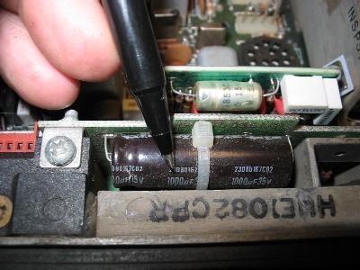
Capacitors C1, C2 and C3 are located on the interconnect board. C3 is either 4.7 µf or 10 µf depending on the vintage of the radio. If you are going to run your Mitrek as a mobile and you find a 4.7 µf cap in your radio as C3 I suggest you change it (or just parallel another one across it) as the higher value improves the receiver audio at really minimal cost. C1 and C2 are 500 µf in the early Mitrek, 1,000 µf in the later Mitrek (if you have 500 µf caps don't bother changing them unless you are putting the radio in mobile service and need lots and lots of speaker audio - like in a fire truck... In a repeater, in link service or as a mobile in a regular passenger vehicle, don't bother).
The lead for pin 16 is not required in 95% of the amateur repeater or link applications - most repeater controllers use separate carrier and PL decode connections rather than one line and a carrier squelch / PL select line. Most radios in repeater or link service usually sit in carrier squelch mode forever, and the repeater controller does all the work in selecting PL or Carrier squelch mode by selecting either the carrier squelch or PL decode line, or ANDing them together. If you end up needing an extra wire in the control connector (like when you want to run both extender on/off and PL decode on a low band radio) you can cut the JU14 / L16 jumper (disabling the carrier / PL switch on the control head) and solder to the pad on the interconnect board that connects to pin 16. Then tie into pin 16 by the head.
The resistor in the bottom lead of the volume control is in most control heads - it is there so that the regular commercial 2-way mobile radio user cannot turn the receiver volume down to zero. In my case, I shorted it out as I was going to be installing the Mitrek link radio at a site where there are many racks of radios, and I did not want anybody in the room to be listening to the conversations on the system. Make your own choice, but if you are going to be inside the head for some other reason, why not ?
If you are trying to build up a minimal system you could mount two trimpots for the volume and squelch pots inside the radio and tie them to the radio side of JU10 / L11, JU12 / L14, JU13 / L15 and to ground. Doing so, however would free up pins 14 and 15 which could be used for other things, at the possible expense of not being able to bench test the radio with a standard cable and head. Or you can mount mini-pots (the ones with 1/8" diameter shafts) inside the control plug shell. If you are going to mount the volume and squelch controls any distance from the radio remember that Moto uses a braided shield around the conductors connected to pins 11, 14 and 15 on the control cable connector, with the shield hooked to pin 2 on the radio end (audio ground) and pin 21 on the control head end.
Don't even try to try and make it work without some kind of a squelch pot - the squelch circuit uses high frequency audio noise from the discriminator to close the squelch when no signal is present. The squelch pot supplies a variable level of discriminator audio to the squelch circuitry. When a signal is present, (up to full-quieting...) the high frequency noise goes down in level to the point of going away completely, and the squelch opens. Without the pot, no audio arrives at the squelch circuit, and without any high frequency squelch noise audio the squelch opens just like it should (because it is assuming a signal is present).
The stock Mitrek volume and squelch pots are audio taper 25k ohms which is not a common value in the electronic component world (especially in the surplus world) - the nearby common ones are 10K and 50K (personally I've used both 10K and 50k pots in several receivers and not noticed any difference). The standard grey Mitrek "clamshell" control head and white MICOR control head uses PC board mount pots with shafts and knobs, and the "ACM" (short for "Alternate Control Module") head uses PC board mount thumbwheel pots. If you are going to mount the controls on a rack panel and you want to be precisely correct in value then you need to locate an old Motrac, Motran or Mocom-70 mobile control head to scavenge the panel-mount 25K pots from. DO NOT try to use the earlier radio's head directly on the Mitrek without modification as the older radios had different control head wiring (and one of the differences was a grounded speaker connection, where the Mitrek runs both sides of the speaker hot to ground). If your old Motrac, Motran or Mocom-70 head came with the palm microphone you can scavenge it and the mic jack and use it on the rack panel as well.
Adding chokes in the leads to the outside world:
If you are going to use a Mitrek that does not have the chokes on the
interconnect board in a repeater system please consider replacing the
jumpers with chokes in the 5 or 6 leads that you use as interface
connections to the outside world. Just take common 1/4w or 1/2w
carbon resistors and use them as coil forms, wrap them in one layer of 24,
26 or 28 gauge enameled wire (three layers if you feel energetic) and solder
the wire end to the resistor lead close to the resistor body. Stretching
the wire slightly before you wind it helps it lie flat (see the trick below),
and a drop of varnish, hot-melt glue, or even clear fingernail polish on the
starting end of each layer helps hold it in place while you wind the rest of
the coil, then another drop on the tail end holds it in place while you solder
the end. Some clear heat-shrink tubing over the entire resistor will
finish the job. As long as the resistor value is several hundred ohms or
more the actual value doesn't matter as the choke will short it out. Personally,
I use whatever value I can get cheap at the surplus store. At the time
I was interfacing the link radios to the controller (i.e. doing the mods
that resulted in this writeup) the local store had 1/4w 10K and 1K resistors
at 25 cents a dozen, and 1/2w 2.2K resistors at a penny a piece. A
free source of enameled wire is the deflection yoke from an old TV
set. Stretch it by clamping one end in a bench vise (or wrapping
a few turns around a fence post or your car's trailer hitch) and string
off 10 to 15 feet of wire and lean back with your whole body
weight... you will feel the wire stretch a little - that's all
it takes. Then wind the choke with the stretched wire and it will
lie flat as you do so. My dad (WB6SOX) taught me this trick - he
claimed to have learned it from a Western Union telegraph lineman in the
1920s to 1930s as they ran the telegraph lines along the road in front
of the family farm outside Cripple Creek, Colorado.
If you decide to improve the RF filtering of a Mitrek and you intend to do all of the mods listed here you will need to replace the jumpers with chokes at pin 1, 7, 8, 9, 10, and 18. The simplest way to add them is to cut the jumper on the connector side of the board, melt the solder and remove the two wire ends, suck the remaining solder out, and install one leg of the choke into the hole that connects to the connector pin, but install it on the side of the board facing inside the radio. Note that three of the jumpers (at JU6 / L7, JU7 / L8 and JU16 / L19) are buried under one of the large speaker coupling capacitors - you will need to temporarily lift one end of one or both cap(s) to access the jumpers.
As long as you are inside the radio lift off the PA deck cover and do a visual check of the tantalum electrolytic bypass capacitors on the positive 13.8 volt supply rails - and use a good magnifying glass and good lighting. Replace any that look suspicious. The failure mode is that they go down in value or open up, and either can allow spurs and grunge... A second problem is that some radios didn't have enough driver stage bypassing. If you still have spurs (rare) add a large value cap on the driver stage +12v lead. Another Mitrek failure mode is intermittent connections in the preselectors, and the Cactus writeup mentioned above has the cure for it, as well as WB4HFN's web page... see http://www.wb4hfn.com/Modifications/MT2311.
In the rest of this writeup I am going to assume that you are either modifying a Mitrek Plus radio (with the factory inductors on the interconnect board) or you have replaced the above mentioned JU6 / L7, JU7 / L8, JU8 / L9, JU9 / L10, JU15 / L18 and maybe JU5 / L1 jumpers with homebrew inductors...
I'm also going to assume that if you are going to use PL, and that you have a factory PL board in the radio. Unless you need simultaneous decode and encode a used HLN4181 is much cheaper than a TS-64 and besides it was made for the Mitrek. These days it makes zero sense to not have a PL decoder, even if you are going to run a carrier squelch repeater. Besides, you can program any decent repeater controller to require PL to do any DTMF commanding. In addition, there are too many times where it would be nice to have the ability to select the other mode. If you don't have a HLN4181 then buy one from a used equipment vendor like Telepath in San Jose, Air-Comm in Phoenix, or C. W. Wolfe in Montana.
UPDATE 2022: All three companies are no more... The name Telepath still exists and they are still a radio company, have a web site but it's a different company.
I have another web page here at www.repeater-builder.com that shows how to make your own TLN6824 PL tone elements for the HLN4181. If you do dig a Com-Spec TS‑32 out of the junk box this web page on connecting the TS‑32 may help. If you use a TS‑64 here's the Com-Spec TS‑64 instructions for the Mitrek.
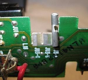
Don't forget to jumper the select line for the Frequency 1 channel elements to ground or you will be scratching your head while you look at a very dead receiver and transmitter. The easiest way to do this is to cut or remove (if present) JU601 and JU610 and insert JU611 (it's near the receiver channel elements, there is a photo below, and when inserted enables both the F1 receive and transmit channel element). Note that JU611 grounds the F1 lead on the front panel connector (pin 7) that we will be using for something else in the next step, but we can fix that very easily.
PL Encoder control
This modification works on both the reedless and the reed
board. Lift the radio side of L6 on the interconnect
board. The radio side is grounded by JU611 so lifting
it is necessary. This disconnects the main board which
disconnects the aforementioned C602 0.01 µf
capacitor. Install a 12v reed relay with the contacts
across JU2 of the HLN4181 or JU3 of the HLN4020 PL board, and
the coil hooked between +12 and the now-floating JU6/L7
end. Ground pin 7, the F1 pin, to close the relay. Select
the normally open or normally closed contacts depending on what the
normal state of your encoder will be... On both of the PL boards
shorting the jumper kills the encoder tone, and in my case I used the
normally open contacts since I wanted the idle state of the relay to
be the PL encoder on. I did not use an open collector transistor
instead of the relay contacts for this because using a reed relay was
easier, faster, simpler, provided an absolute zero-ohm ground (the
less resistance you have, the better the tone cutoff) and in my case
the encoder off function is only used for a few hours once or twice
a year (so I definitely wasn't going to wear out the relay). I
was also doing this conversion on a rapid deadline - from concept to
installation of fully operational hardware in a few weeks, and on
this particular project I used proven circuitry as much as possible
to minimize any R&D and debugging time. We also had the concern
that the equipment was going to a limited access site - not only did
we have to do it quickly but the finished equipment had to be
ultra-reliable. Note that if your controller does not have a
back-EMF snubbing diode on the digital output make sure you add one.
If I was going to do it all over again, I'd use a FET instead of the
reed relay and that would allow me to key the PL encoder with the main
channel receiver COS signal without worries of a worn-out relay. You'd
need a FET with low "on" resistance, and the source and drain leads
would go in place of JU2, with the gate lead through a resistor to
the F1 pin. Or I might use an opto-isolator between the F1 pin
and the FET... Several manufacturers make FET-output optoisolators,
so there is second sourcing. In other words, don't use
single-manufacturer-sourced parts unless you really have to and
have sufficient spares on hand.
PL Decode
All connections between the radio and the PL board are made through the 9-pin single-in-line connector header which looks like a vertical brown line in right edge of the photos below. The holes in the board provide access to tuning adjustments in the receiver. The three boards are completely interchangeable except for the setting of the encoder level pot on the board. |
||
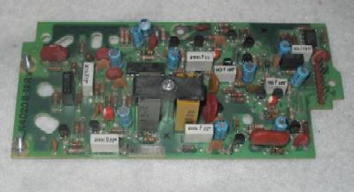 Photo 11: The HLN4020 reed-type board. |
||
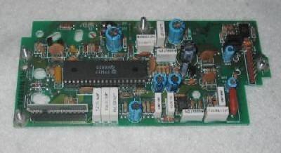 Photo 12: The HLN4181 reedless board. |
||
 Photo 13: The HLN4011 DPL board. |
||
While perusing the schematic of the HLN4020 reed board I did notice one nice feature: it can be jumpered to use one reed for common encode/decode or two reeds for split tones. I've not seen that feature in any other reed-based PL board. When two reeds are used the encode reed is on the left of the hold-down bracket in the above picture with the decode reed on the right, when one reed is used it goes in the encoder socket and two jumpers are added. The necessary jumpers are documented in the later schematics of the board (they are not included in the board revision D schematic but they are there are on the revision F schematic). An early board can be jumpered for a single reed using the info from the later schmatic.
For more information on the HLN4020 dual-reed board, the HLN4181 reedless board and the tricks they can do, plus information on how to build your own TRN4224 tone elements please see my HLN4181 web page.
The rest of this section is focused on the HLN4181 "reedless" tone PL board since I had seven radios with five HLN4181s, and only one of the HLN4020 reed board and one HLN4011 DPL board. Working for NASA for six years taught me that you don't put equipment into mission-critical service (i.e. on a mountaintop) that you do not have known-good and ready-to-go spares for on the shelf. Service trips should be limited to swapping entire units out, not fixing them on site (unless that is the absolute last resort)... especially if it takes you a couple of driving hours to get to the start of the twelve mile long dirt road, and another hour or two in 4-wheel-drive to get up to the radio site... and that's in good weather. Naturally Murphy's Law says that things will fail (locking every transmitter on - even the links) during a five-day-long snow storm that starts the week after the road washes out in the biggest rainstorm in twenty years...
The HLN4181 reedless board can be set up in several ways... The
normal configuration of jumpers (and the most useful one) is listed in the
table below... The board can NOT run simultaneous encode and
decode - the encode portion generates the PL tone continuously and the PL
decode output goes active when the PTT line goes active. I initially
wrote this writeup in 2002, and at time thought that the board would work
as a duplex (i.e. simultaneous) encoder-decoder, but never tested it
as I always used two radios, one for transmit and the other for
receive. It wasn't until 2006 that someone told me that a
duplexed radio would not run in PL when using the HLN4181 board as
both the encoder and decoder.
I haven't tried this, but looking at the schematic suggests that you could
cut the trace from pin 4 to E2 to lock the board in receive mode, and use
an external encoder. Or if you don't have a HLN4181 just
use a Com-Spec TS-64 (which does do simultaneous encode and decode). And you can use the '64 info
to interface a TS-32 if that's all you have.
| HLN4181 Reedless Mitrek PL Board Factory Jumpers | ||
| Jumper JU- |
Normal setup |
Function |
| 1 | OUT | Normally used to couple the internal PL tone encoder to equipment outside the radio |
| 2 | OUT | Disables the internal encoder when in place |
| 3 | IN | In to couple internal encoder to the transmitter modulator (and remove JU7) |
| 4 | IN | Install for "AND" squelch (and remove JU5) |
| 5 | OUT | Install for "OR" squelch (and remove JU4) |
| 6 | OUT | Install to disable PL decode (receiver carrier squelch only mode) |
| 7 | OUT | In to connect external encoder (fed from
control connector pin 18) to transmitter modulator (and remove JU3) |
| 8 | OUT | In to disable the encoder's reverse burst |
| 9 | IN | When installed couples receiver discriminator audio into the PL decoder. Note that some early revision boards do not have a JU9. |
| If your HLN4181 board has JU1, JU6
and / or JU7 in place, remove all of them. If
you want your PL decoder to work then JU9 must be
installed. If you want the PL encoder to work then JU3 must
be installed and JU2 must be removed. If you are in a situation where the local speaker will be used and in a PL environment then in most cases you want JU4 in place and JU5 out... AND squelch is much, much more pleasant to listen to than OR squelch. JU4 and JU5 are redefined if the radio has the HLN4119 "Busy Light" option (very rare)... for more information see the footnotes on the receiver and control head schematics in the manual. The radios that do have the busy light option must be paired with matching control heads (the "busy light" heads have an 8-pin IC installed into the only IC position on the circuit board inside the head). |
||
A PL decode signal is available at the collector of Q1 of the HLN4181 PL board, which is available at one end of the JU6 jumper. This transistor takes the PL decode signal from the custom chip and inverts it before sending it to the audio mute transistor (located on the main board). I used a length of insulated wire to run that signal over to the end of the JU1 jumper that feeds pin 1 of the 9-pin connector that connects the PL board to the interconnect board of the Mitrek. The connections are pretty obvious when examining the schematic, and are easily traceable when looking at the actual circuit board.
You will need a monospaced font (like Courier) to view this diagram properly.
    +12v
     !           add this jumper
     R 94k   +----------------------------+
     !       !                            !
     +-------O -JU6- O--        --O -JU1- O---+------+
     !         (out)                (out)     !      !
 Q1  C                                        !      !
 --B                  to other  --O -JU7- O---+      !
     E                circuitry     (out)            !
     !                                               !
    gnd                                              !
               HLN4181 PL board                      !
                                                     !
                                                     !
+--------------------<<------------------------------+
!                 9-pin PL Board
!               connector P3 pin 1
!
!                        L18
+---O --JU3A-- O------O -JU15- O---Pin 18 of the control connector
      (added)            (in)      CTCSS Decode out
                                   (to repeater controller CTCSS decode in)

             Interconnect board
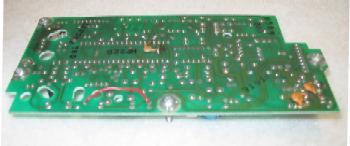 Photo 14: This is what the JU1 to JU6 jumper looks like. I installed it on the foil side of the board since that's what you see first when you pop the lid on the radio. You can also install it on the component side of the board. |
Note: On the interconnect board make sure that jumper JU3A is installed, and that JU3B and JU3C are out. This connects the PL decode indication on pin 1 of the PL board connector to pin 18 of the control connector - requiring nothing more than a funny jumper on the PL board and a short jumper on the interconnect board. Normally pin 18 is used to bring the tone from an external PL tone encoder (mounted in the control head) into the PL board - here we're using it to route the PL decoder logic level output to the controller by the same path. I've seen other Mitrek modification web pages that use pin 18 for other things such as transmit audio or COR, but I much prefer using it for the PL decode logic level -- it's just a "cleaner" mod (and besides there are four more frequency select pins available for the other signals).
 WRONG ! |
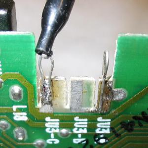 |
| Photo 15: Above is a picture of JU3A and how the Mitrek designer at Moto expected you to jumper it. It's a cute, inventive and resourceful idea but those 1/4 inch tab connectors fall off in mobile service, even if you squeeze them very tightly and push them on with pliers. | Photo 16: Personally, I bend up a piece of bare copper wire into a hairpin and solder one end to one side of the board and the other end to the other side (the right side wire in this picture is the actual JU3A tone decode jumper). I leave an air gap under the loop so I can clip an EZ-Hook™-style test lead to it. I also install a wire on the left side simply as a handy ground point (one side of JU3C is ground) for a VOM or an oscilloscope probe (the left hand wire in the photo). |
Note that this voltage from the collector of Q1 is not a true high or low logic level - it will drive the PL decode input of most repeater controllers just fine, but if you need a signal that goes all the way to ground - for example to drive a LED (perhaps in a control head) you'll need to add a driver transistor. The version below provides an open collector output for the PL decode signal. If the upper transistor has enough gain the lower transistor may not be needed (see above for the rest of the details).
    +12v
     !                     --O -JU1- O--------->>--- CTCSS Decode out
     !                         (out) !      P3 pin 1
     !                               !
     !                          +----+
     !                          !    !
     !               100k       C    !
     R 94k    +--------R----- B      !
     !        !                 E    !
     +--------O -JU6- O--       !    !
     !         (out)            !    C
 Q1  C                          +--B    two 2N4401, 2N3904, 2N2222, etc
 --B                                 E
     E                               !
     !                              gnd
    gnd              (available at several locations, one of which
                      is one side of JU2, another is test point E3,
                      a third is pin 9 of the PL board connector)

              HLN4181 PL board
My first version of this setup used the plain JU-1 to JU-6 jumper described above, and drove an Scom 7K directly (the Scom uses 2vDC as the threshold between the inactive and active states). I added the transistor driver for the PL decode LED inside the control head. My second version (above with the two transistors) was used on a home-brew controller that needed a PL decode signal that went all the way to ground. The two transistors drove both the controller and a LED just fine.
    +12v (junction of L3, C43 and R45)
     !
     +-----R-------+                --O -JU1- O--------->>---- CTCSS Decode out
     !    see      !                    (out) !      P3 pin 1
     !    text     !                          !
     !         +---------------------------------+
     !         !                                 !  6N135
     !         ! LED                     photo-  !  Opto-isolator
     !         ! emmitter             transistor !  with open
     !         ! side                     side   !  collector
     !         !                                 !  output
     R 94k     +---------------------------------+
     !             !                          !
     !             !                          !
     +-------------O -JU6- O--               gnd
     !               (out)
 Q1  C
 --B
     E
     !
    gnd              HLN4181 PL board
If I were to do this over today I'd use the circuit above - I'd use the existing transistor on the PL board to drive the LED side of an open-collector optoisolator such as the 6N135 (effectively shunting the 94k resistor to the point that it pretty-much drops out of the circuit). The resistor in series with the LED side (the one shown without a value) would have to be selected to pass enough current to turn on the opto-isolator's LED fully on without going into overcurrent (check the spec sheet for the optoisolators LED). The use of the optoisolator makes this circuit pretty universal.
Note that in the circuits above that the new CTCSS output is independent of the audio mute circuitry - the new CTCSS output is just a logic level indication as to if there is a proper tone present or not. I just leave the receiver in carrier squelch mode forever. The COS output indicates if the channel is busy or not, and the CTCSS output indicates if the channel has the proper tone or not. The repeater controller combines the two signals and the audio muting is done in the repeater controller.
If your target environment is IRLP, then note that the IRLP interfacing board does not have separate PL and COS inputs - it has only one input (and the default is active low, but can be jumpered for active high). In this case, you would hook the Mitrek COR signal (actually the audio mute line) to the IRLP COS input and use one of the three AUX outputs (each uses a 6 amp FET) to drive the PL / Carrier select line. Or the FET can drive a reed relay whose contacts are hooked to the PL / Carrier line. Then you can modify the IRLP custom decode script file so that you can use touchtone commands to switch the appropriate AUX lead on and off, selecting PL or Carrier squelch. I suggest using AUX3 as AUX1 is frequently used as an auxiliary PTT control in the IRLP system.
Using a separate PL encoder with the
HLN4181
The design of the reedless board uses the encoder as the frequency
reference for the decoder function, and as such it can't run split
tones (i.e. different encode and decode tones). If you need
to run simultaneous split tones in a single duplexed radio you will
have to add a second device, either a PL encoder or decoder. Having
done both, I can tell you that it's much easier to add an encoder. I've
used home-brew twin-T oscillators since HT200 days (which worked surprisingly
well when built with metal film resistors and polystyrene caps),
Cetec-Vega 188's (very small, the tone is selected by varing a 20-turn
trimpot), Com-Spec SS-32s, TS-32s, SS-64s, and TS-64s (the SS-nn is
the encode-only version of the equivalent TS-nn product). The
TS-32 series does not have
reverse-burst (unless you add an RB-1) board, the TS-64 does. There
is more information on the SS32, TS32, SS64, TS64 and RB-1 on
Com-Spec web page here at
Repeater-Builder. While the Cetec-Vega 188 is a discontinued
product it is an encoder-only, is fully documented on the "Other
Manufacturers" web page at this web site, and is simple enough
that you could build it from the documentation. If you use
a 10 or 20-turn pot and good quality resistors and capacitors then
it will work as well as any Com-Spec encoder.
Or you might have an alternate tone source - for example the Scom 7330
has a three excellent CTCSS encoders built in, one for each radio port.
The hookup of an add-on encoder is fairly simple:
Connect the audio output of
the separate encoder here ---------------------------+
                                                     !
And the associated gnd                               !
to here, ---------------------------------------+    !
or or to one side of R2                         !    !
or to test point E3                             !    !
or to P3 pin 9                                  V    !
                                               gnd   !
                                                     !
Control                              P3              !   R27
connector    L18                    Pin 1            V   22K
Pin 18 ---O -JU15- O-----O -JU3A- O--<<---+--O -JU7- O----R--+
            (both jumpers are on          !    (out)         !
            the interconnect board)       !                  !
                                          !                  !
                                          !                  !
      +----------------------------+      !                  !
      !        added jumper        !      !                  !
      V                            V      !                  !
  ----O -JU6- O--        --O -JU1- O------+                  !
        (out)                (out)                           !
     PL decode from previous section                         !
                                                             !
                                                             !
   alternate insertion point for PL encoder ---+             !
                                               !             !
                                               !             !
         R25 4.3K      R25 4.3K                V             !   C24
 -----------R------+------R------------O -JU3- O-------------+----C---  to filtering
audio from         !               (normally in but          !  1.0 µf  then to
internal PL        !               but remove it when        !          transmitter
encoder        Thermistor          using a separate          !          modulator
                   !               encoder - see text)       !
                   !                                         O <-- Test point E1
                   !
                   R  R29
                   !  6.2k
                   !
                   +-----O <-- Test point E3
                   !
                   +-----O <-- Pin 9 of PL board connector P3
                   !
                  gnd
Note that JU3A is on the interconnect board and JU3 is on the PL board. JU7 is normally used with applications that used external PL encoders built into the control head - these fed the PL tone in starting at control connector pin 18 then going through JU15, JU3A and JU7.
If you mount the new encoder inside the radio you can use pin 18 as the COR output lead or anything else. The internal +9vDC from the stock PL board can power it, and use the Frequency 1 line to switch it on and off.
Before connecting the new encoder leave JU3 on the PL board in place and make sure JU7 is out. Then key the transmitter and measure the existing encoder's audio level (AC voltage) at test point E1 and write it down. Now remove JU3 and connect the new encoder's audio output to the R27 side of JU7. Ground can be acquired from one side of R2 nearby, from one side of JU2, from test point E3 or from pin 9 of P3 (the 9-pin connector to the interconnect board). Depending on what DC supply voltage your new encoder requires you can find filtered +12v on the wide trace that connects L3, C43 and R45, or you can get regulated +9.1v from the trace that ties pins 31 and 6 of the 40-pin chip together, or from the solder pad shown in the photo below. With the AC voltmeter back on E1 you can now set the level of the replacement encoder to match the original encoders output. If you are running separate transmit and receive radios you can also locate the external encoder outside the radio and use the interconnect board JU3 and PL board JU1 and JU6 and JU7 jumpers in the transmitter radio like they were intended... Note that the above implementation will not have reverse burst, as that is generated inside the HLN4181 board's custom chip. If you need reverse burst you can use the external PL encoder that was designed for the Mitrek or MICOR "System's 90" control head setup (they show up on ebay from time to time), or a Communications Specialists RB-1, or the TS-64 encoder that has it built in. Here's Com-Spec's own writeup on the TS-64 for the Mitrek. It's not oriented to using it as an encoder-only, but the encoder and reverse-burst hookup is quite relevant. The older TS-32 will work just as well, but it does not have reverse burst (unless you add an RB-1, or build your own clone of it).
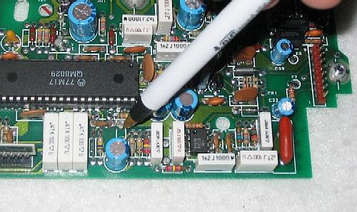 Photo 17: You can find +9.1v DC to power the external PL encoder in the empty solder-filled hole just above the pen (which slipped just as the flash fired...) |
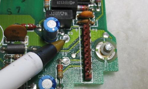 Photo 18: Test point E3, pointed to by the pen, can be used as the ground connection for your PL encoder. |
Repeat Audio In
Bringing transmitter audio (i.e. repeat audio) into the radio from
the outside world is simple because the Mitrek is a true FM radio
and the actual modulation is done inside the channel element. All
we have to do is to tap the modulation line going to the row of transmit
elements and and insert our audio. There is an easy way and a right
way... Both take a 10 µf audio coupling capacitor and
connect it from the control connector's frequency 4 select pin through
the RF protection choke to the modulation line of the transmitter channel
elements (pin 4). The difference is where we tap into that modulation
line.
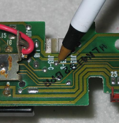 Photo 19: The easy way is to just patch a 10 µf capacitor onto the interconnect board between JU9 / L10 and this plated through hole. |
>----------------------------------------O -JU3A- O--+--O -JU15- O---Pin 18 of the
9-pin PL Board                              (in)     !     L18       control connector
connector pin 1                                      !
                                      +--O -Ju3B- O--+  <-- Moto uses this jumper to feed an
                                      !     (out)           external PL encoder (tied to pin 18)
Transmit       JU9/L10       10 µf    !                     into the radio modulator
audio in        choke        -! !+    !
>-------------()()()()--------! !-----O <-- plated-through hole
control head               ^  ! !     !     on interconnect board
connector pin 10           !          !     right below and in between
(Frequency 4 select)       !          !     JU3B and JU3C.
                           !          !
                           !          +--O -JU3C- O <--- this is where I grab my VOM
lift the main-board side --+          !     (out) !      or oscilloscope ground
of the choke and connect              !           !
the new capacitor to it)              !          gnd
                                      !
                   interconnect board !
                       ==============================
                           main board !
                                      !      O "Point B"
                                      !      !
                                      +------+---- to transmitter modulator
Note: do not use a tantalum cap in the above schematic,
they are bad news when used as audio coupling capacitors.
The better way to insert repeat audio into the transmitter is to run one end of that same coupling capacitor to the main board. Find "Point "B" on the schematic and then on the main board near the mic audio circuit, look around Q1004, R514 and R501, it can be a little hard to find without a photo (which I've provided below)... The "Point B" is preferred as connecting the capacitor there bypasses the connection beteween the interconnect board and the main board, which according to the Cactus writeup mentioned above "has been found to be the cause of intermittent and high resistance connections". They aren't kidding. The main board to interconnect board connectors were a weak point in the Mitrek until Moto changed the connector plating metalurgy... read on...
Milt N3LTQ pointed the following out to me in an email:
On the Mitrek interconnect board take a look at the color of the plastic on the pins that connect the interconnect board to the main board in the radio. If the PL connector plastic is WHITE, get a book and order out a new set of main board-to-interconnect board pins and sockets. If the PL connector plastic is RED in color you already have the new version connectors (the plating metalurgy is different).Take your time and carefully remove the old connectors and replace them. Sacrifice the old connectors rather than risk damaging the board traces (one way is to saw the plastic apart with a circular saw blade in a Dremel Moto Tool). The new connector metallurgy will fix many intermittent problems.
...the problem was bad enough that Moto came out with Field Modification Kit, part number RPX4277A (which is no longer available), however the new PL board connector (red plastic, 9-contact J3) is part number 0980140H02, at about $3.50, and the new main-board to interconnect-board connector (white 25-contact J10) is # 0980140H03, about $6 for a pack of two.Thanks to Eric for the kit number, the connector part numbers and prices.
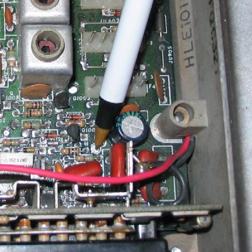 Photo 20: The right way is to inject it into test point B, pointed to by the pen. Don't be surprised that the hole in the PC board is big, it's sized for a push-on-pin. |
This is the right way:
Transmit       JU9 / L10              10 µf
audio in        choke                -! !+
>-------------()()()()----------------! !-------- connect to
control head               ^          ! !         "Point B" on
connector pin 10           !          new         main board
(Frequency 4 select)       !       capacitor      (see text)
                           !
lift the main-board side --+
of the choke and connect the
new capacitor to it
Important! Note that the transmitter audio injected at the modulation line by either method shown above is NOT pre-emphasized by the transmit audio circuits in the radio before modulating the transmitter. If you need pre-emphasis (most do) you need to do it to the audio before it hits point B. The AP‑50 board sold by Repeater-Builder does this quite nicely.
You may find that the local mic audio is a little low when the radio's deviation pot was set properly and the repeat (transmit) audio level out of the controller is adjusted properly. This is dependent on the output impedance of the audio source (the repeater controller). Sometimes, as in my case, it's "fixable" if the person "close talks" the microphone (with the lips just barely clearing the mic grille) and speaks at a level just a little above normal conversation level. As often as I go to a hilltop site and need to use the link radio's local microphone I can live with having to close-talk and "speak up" a little (it is perfectly acceptable for test use). If you find it a problem, just add a series resistor between the repeater controller output and the "Point B" (i.e. raise the controllers output impedance), then tweak up the audio level from the controller to compensate.
Comments on the stock Mitrek Receiver Carrier Squelch
Modern FM radios utilize a noise operated squelch which works by
measuring the amplitude of the discriminator white noise at the
audio frequencies above the frequency range used by the human
voice. Speech lives in the range from 250-300 Hz to a certain point,
above that is all noise. The cutoff frequency between what is
considered voice and what is considered squelch noise is critical - too
low and the squelch will chop on higher pitched voices, too high and
there won't be enough high frequency noise to work with (the top
frequency of the available noise is controlled by the high frequency
knee of the IF bandwidth curve).
Imagine a bench setup with an RF generator connected to the receiver antenna connection, the squelch is wide open, and an AC voltmeter is connected to an audio dummy load hooked across the the speaker leads. Set things up with the generator cranked to minimum, and the AC voltmeter is showing a volt or two of noise. As you slowly increase the level of an on-channel dead carrier, the level of squelch noise quickly lowers with just a little bit of signal. If you reduce the carrier level the noise comes back up. Receiver sensitivity is measured this way, look for the "20 dB quieting" measurement in a radio specification sheet (and some point-to-point links - especially voting receiver links - need 30, 35 or even 40 dB of quieting). The noise operated squelch circuit takes this high frequency AC noise, amplifies it and rectifies it into a DC voltage that varies with the noise level (this is the Received Signal Strength Indicator (RSSI) voltage that folks pick up and send to an analog metering input on several brands of repeater controllers). When this DC voltage drops below a specific threshold (set by the squelch control) the speaker unmutes (i.e. squelch open), and as it rises above the threshold the speaker mutes (squelch closed). Most modern radios use two different thresholds (the difference is called the squelch hysteresis amount), a slightly higher one for squelch open, and a slightly lower one for squelch closed. Using two voltages improves how the user perceives the squelch action: once the squelch opens the signal can drop back past the squelch-open threshold level and then drop a little more before it closes.
Many people are dissatisfied with the stock Mitrek squelch, especially if thy have ever been exposed to a MICOR or a GE MASTR II. The typical complaint is that that the squelch threshold level (to stop the white noise in the speaker) is much lower than the level required to eliminate the random "cracklies" caused by on-channel noise spikes. In other words to get a totally quiet receiver the Mitrek squelch control has to be set much higher than the initial squelch-closing threshold - in some cases turning the squelch control all the way to the top isn't enough.
The reason for the poor performance of the Mitrek carrier squelch circuit is inherent in the overall design. The entire circuit uses only only five transistors, one of which is the main audio mute transistor. The Mitrek was designed in an era where the use of PL or DPL was universal, and carrier squelch had gone by the wayside. It really looks like the Motorola designer didn't put much time or thought into it, almost seems to have been included as an after thought... probably knowing that it wouldn't be used much... it's just a very simple noise operated squelch.
In contrast, Motorola put a great deal of effort into the previous generation radio - the MICOR. They had to since the use of PL and DPL had not become universal at the time of its design. In short, the MICOR was the high water mark for carrier squelch (noise squelch) circuit development... it just works better than anything else on the air. The heart of the fabulous MICOR carrier squelch circuit is a single custom IC chip which contains over a hundred transistors that implement a complete bi-level or switched hysteresis squelch system on a single chip. Unfortunately this part is obtainable only as a spare part from Motorola or by carefully scavenging it off of a MICOR audio-squelch board (and it's not socketed). Note that the circuit could be added to any model radio - even the infamous Modar Triton / Metrum II. In fact, it's not hard to hook an inexpensive MICOR mobile Audio-Squelch card (available for $5 or so) to almost any radio that has raw discriminator audio and positive stable 9.6v-10v DC voltage available. A 10 K, 25 K or 50 K squelch pot completes the circuit (if you are interested in doing this, look at any MICOR mobile manual and trace the receiver discriminator audio through the audio squelch card to the audio PA transistors). The schematic of the MICOR audio-squelch card is available as a download from this web site - look on the MICOR page.
Naturally, when a need shows up, somebody fills it for a price. One vendor is Link-Comm, who makes a line of repeater controllers. One of their support products is an accessory board called the "RLC-MOT" that will add a MICOR squelch into any receiver that provides raw discriminator audio. The board will fit inside any mobile radio, is much smaller than the actual MICOR audio-squelch board, works great, makes the squelch action a lot more pleasing, and eliminates the squelch tail the stock Mitrek creates. It's also transferrable to a another receiver later on.
 Photo 21: The Link-Comm RLC-MOT module is small, only 2.5 inches by 1 inch |
The RLC-MOT interfaces with a single six pin connector:
By the way, pin 1 is a square pad, the others are round pads.
RLC-MOT pinout Pin Function 1 +11 to 15vDC at about 35ma 2 Discriminator audio in 3 Buffered and muted audio out 4 Active low COS 5 Active high COS 6 Ground
Pin 6 is nearest the corner of the board, and the trimpot adjustment screw.
The RLC-MOT uses a (20 turn!) precision trimpot for an on-board squelch control, has a LED that lights when the squelch is open, and also has an audio level pot on board. You can demount the trimpot and run leads to a front panel pot if you desire. Note that the audio level pot is a single turn pot and has no stops, so adjust with care.
If you are using an RLC-MOT module and need a de-emphasized repeat audio output you can take advantage of the fact that the option of de-emphasizing the audio was designed into it from the start - just add a capacitor across R9 on the module itself. There are solder pads for it already in place (labeled C18). They are small and you will have to use a very small cap and a very small soldering iron, and work quickly and carefully but they are there. Depending upon the audio response you'd like to see, the cap should be somewhere between .0075µf (breakpoint at about 200 Hz) to .022µf (breakpoint at about 75 Hz). While you can tailor it to suit your desires of low-frequency response the lower you go in frequency the less "effective gain" you will achieve due to the modification of the buffer/amp circuit's frequency response. A 0.01µf cap will give you a breakpoint of 150 Hz, which is a good compromise, or if you want to use a lower PL tone you might want to go to a 0.015 cap. The RLC-MOT is available from RLC Controllers for about US$60 (at the time of this writing). Yes, I know, you spent less on the entire Mitrek mobile radio - but if you blow up the Mitrek you can move the RLC-MOT to a follow-on radio (the author has added one to a Kenwood, to a Motrac, to a MASTR II and, as a joke, to a 1950's Sensicon-A tube-type receiver, which even today, over 50 years after it was built, is still one outstanding performer... and moving it to 220 MHz is simple - just apply a short across each of the tuned lines at the right point, change the crystal and peak the front end!!).
The audio feed to the RLC-MOT must be right from the detector, from before the de-emphasis network in the radio. It can be derived from two places: purists can take if from pin 1 of U403A in the receiver, bypassing the main-board-to-interconnect-board junction (suggested) or from the radio side of JU10 / L11 (which feeds pin 11 of the control connector).
You can mount the RLC-MOT using screws and standoffs, or with double-sided foam tape. Just make sure that you it in such a way that you can get to the squelch adjust pot (labeled R3), the audio level pot (R14) and to be able to observe the squelch open / closed indicator LED (D1).
More info on the MICOR squelch is at:
A quick-and-dirty hookup of the RLC-MOT to a Mitrek - NOT RECOMMENDED:
+-------------------+
!     Function  Pin !
!                   !
!          +12   1  !------ +12v
!                   !
!     Audio in   2  !------ See text
!                   !                         choke
!    Audio out   3  !-----------------------()()()()----< <--- repeat audio out (to controller)
!                   !                        JU8/L9    Pin 9 - Freq 2 select
!  Low COS out   4  !-----------------+
!                   !                 !      choke
! High COS out   5  ! unused          +-----()()()()---< <--- Active-low COS out (to controller)
!                   !                        JU7/L8    Pin 8 - Freq 3 select
!          GND   6  !--+
+-------------------+  !
                       gnd  <-- pin 6 or 17 of the control connector, or
                                any other internal audio ground
Here's a better way to do it:
I really, really suggest that you use the "High COS Out" signal to drive
an open collector transistor as shown below, with the collector going to
the outside world via JU7 / L8 / pin 8. Doing
this will protect the RLC-MOT module from any errors in hookup outside
the radio - I'd much rather toast a 25 cent (or less) transistor than a
US$60 module... the transistor takes the heat, so to speak.
                                          choke         pin 8
     pin 2 ! audio in                     +---()()()()-----------<
           !                              !    JU7/L8        F3 select
     pin 3 ! audio out                    !
           !                              ! <--open collector COS output...
     pin 4 ! Low COS out                  !    low when squelch open / signal present
           !                              C
     pin 5 ! High COS out ---------R--- B
           !                      3.3     E
           !                      or      !
           !                      4.7 K   !
                                         gnd
Here's the right way to do it:
If I were to do it over today I'd use the RLC-MOT to drive an open collector
optoisolator (like the 6N135), in a socket, instead of the open collector
transistor.
                                                                  choke         pin 8
                      +12-----/\/\/\/\---+              +--------()()()()-----------<
                                         !              !         JU7/L8    F3 select
                                       +---------------------+
                                       ! LED           photo !
     pin 2 ! audio in                  ! emitter  transistor !
           !                           ! side           side !
     pin 3 ! audio out                 +---------------------+
           !                             !              !
     pin 4 ! Low COS out                 !              !
           !                             C             gnd
     pin 5 ! High COS out --------R--- B
           !                     3.3     E
           !                      or     !
           !                     4.7K    !
           !                            gnd
Modifying the Mitrek so that you can hear the RLC-MOT output:
If you want you can disconnect the top end of the Mitrek volume control (as shown below) and feed audio from pin 3 of the RLC-MOT to it. This will allow you to use the Mitreks internal audio amp and local speaker to monitor the repeat audio (which is really handy while on the workbench). Just break the connection as shown below, connect the high side of the volume pot to a spare pin on the control head connector then run an extra lead from the RLC-MOT inside the radio to that pin on the head. Note that this connection expects NON-de-emphasised audio since the de-emphasis circuitry in the Mitrek is after the volume control. In other words, if you are going to do this, do NOT add the C18 de-emphasis cap on the RLC-MOT circuit board.
                                                    Break here
                                                     /
        +!!C3                                       /
radio----!!---JU10---Pin 11 -----------Pin 11---+--X--+ <---insert RLC-MOT audio here
main     !!   L11    Buffered          on head  !     !
board                audio out                  !     !
                  (unsquelched)                 \     \
                                          3.3k  /     / 10k    This resistor
                                          1/4w  \     \ 1/4w   can be jumpered
                                           or   /     /  or    if you insert the
                                          1/2w  \     \ 1/2w   RLC-MOT audio at the
                                                /     /        top (above)
                                                !     !
                                                !     ! <---or leave the top of the resistor
                                                !     !     above alone and break this
                                                !     !     connection and insert the RLC-MOT
                                                !     !     audio at the top of the volume
                                                !     !     control
                                                !     !
                                       25k pot  \     \ 25k pot
                                       Squelch  /     / Volume
                                                \     \          to pin 15 on
radio---------JU12---Pin 14 -----------Pin 14-> /     / <------- head then to
main          L14    Squelch           on head  \     \          pin 15 on radio
board                wiper                      !     !
                                                !     !
                                                !     \ This resistor can be
                                                !     / be jumpered - see the
                                                !     \ text in the Control Head
                                                !     ! Connections section above
                                                !     !
radio----------------Pin 2-------------Pin 21---+-----+
main                 Audio             on head
board                ground
Using the receive audio stage as a monitor amplifier:
Simply connect the top of the volume control to an SPDT switch,
with one side to pin 3 of the RLC-MOT, and the other to the
repeat audio input (i.e. the audio from the controller to the
transmitter). You might have to add a trimpot on one side
to make the audio levels equal... The ability to monitor
the transmitter audio lets you hear what the users are hearing - the
repeated audio complete with the controllers courtesy beep, the
identifier, etc. and will reveal any mismatched audio levels (for
example, between the identifier, the DVR playback level and the
user audio). As said above, that there is a de-emphasis
stage downstream from the Mitrek volume control and trying to
monitor additional audio sources that have already been de-emphasized
will sound really bad... See the articles on pre-emphasis and
de-emphasis on the Tech Articles page.
from channel element pin 4 buss----cap to block DC---+
                                                     !
                                                  insert
                                                  trimpot
                                                 to ground
                                                   here
                                                 if needed
                                                (to adjust
                                                audio level)
                                                     !
                                                     !
                                                     O
                                                      <---o---- to volume control high side and
                                                     O          then to the de-emphasis network
                                                     !
                                                  insert
                                                  trimpot
                                                 to ground
                                                   here
                                                 if needed
                                                (to adjust
                                                audio level)
                                                     !
from RLC-MOT audio out-------cap to block DC---------+
                               (if needed)
I've also seen asystem that had a MICOR repeater and several
Motrac / Motran receivers used as link receivers. The toggle
switch above was replaced by a multi-position rotary switch, with position
1 as the exciter audio, position 2 selected the repeater receiver, the
next two positions selected the audio to and from the IRLP node, the next
two selected the audio to and from the remote base, the next four selected
the audio to and from the two link radios and the rest selected the audio
from the voting receivers. Note that this selector system requires that
the audio be all de-emphasized or all "flat"... otherwise your monitoring
system can get to be more complex than the repeater... simplest way is to
tap the monitor audio after the de-emphasis network in each receiver.
Carrier Operated Relay (COR)
Carrier Operated Switch (COS)
Carrier Detect (CD)
Channel Busy (CB) (you choose the term you prefer)
So what is COR / COS /CD / CB ?
This is a logic output (a DC voltage) produced by the radio that changes state whenever the squelch is opened. This signal is required for repeater controllers and IRLP nodes to know when the receiver is receiving a valid signal. Back when radios had tubes and glowed in the dark the common technique was to add another tube that drove a sensitive low-current relay, which pulled shut when the squelch opened and dropped out when the squelch closed, hence the term "Carrier Operated Relay". One set of contacts on this relay keyed the transmitter PTT lead. A "carrier delay" capacitor kept the relay closed for a few seconds - this prevented a fluttery or weak signal from banging the COR and PTT relays to an early death, and was sometimes treated as a seperate timer stage, and referred to in the documentation as the "carrier delay timer" or the "hang-in timer". When switching transistors relaced tubes, the term became Carrier Operated Switch, or COS. Early mobile telephone systems ran carrier squelch, and every mobile unit had a light labeled "Channel Busy" on the control head (it was driven by a COR circuit). In the computer data communications world one of the standard modem status signals is CD, or "Carrier Detect". It's all the same - a signal that indicates that the channel is in use, or the receiver squelch is open.
I seriously suggest you use the Link-Comm RLC-MOT board (as described above) to generate the COR signal and repeat audio outputs, but if you chose not to, then generating your choice of an active-low or active-high logic-level signal that indicates open squelch isn't hard, but it does need one NPN transistor, maybe two, depending on your preferences.
To bring the COS signal outside (from either the RLC-MOT or from the added switching transistor) I lifted the radio end of JU7/L8 on the interconnect board leaving the choke between control connector pin 8 and the COS signal source.
     Original !  Added carrier
      Mitrek  !  detect circuitry
     --------------------------------
              !
              !                     Positive
              !                     DC voltage
              !                    (+5 or +12)
              !                        !
              !                        !    Leave out the 10k resistor for
              !                        !    an open collector, or connect
              !                      10K R  to +5 or to +12v if you want
              !                        !    that voltage as your high level.
              !                        !    +12 can be found on the control
              !                        !    connector pin 4.  +5 can be
              !                        !    generated by a 2-resistor
              !                        !    voltage divider.
              !                        !
              !                        !    Most repeater controllers that I have
              !                        !    worked with expect open collector.
              !                        !    Some have their own pullup resistors.
              !                        !
              !                        !
              !                        !  JU7 / L8 choke     pin 8
              !         control        +------()()()()----------------<
              !        connector       !  ^                F3 select
              !          pin 4         !  !
              !           +12v         !  +--lift this end of the
              !            !           !    choke in the radio from
              !            !           !    the existing circuitry
              !            !           !    and hook to new
              !            !           !    transistor collector
              !        10k R           !
audio    !    !            !           ! <--open collector COS out...
mute     !    !            !           !    low with squelch open / signal present
switch   !    !            !           C
Q406     C    !            +---------B
    -- B      !            !           E
         E    !            !           !
         !    !            C           !  Two new transistors are almost
         +--------R------B             !  any NPN silcon - 2N4401s,
         !    !  10K       E           !  2N3904s, 2N2222s, etc.
  R414   R    !            !           !
150 ohm  !    !            +-----------+
         !    !            !
        gnd   !            !       pin 6 or 17 of the control
              !           gnd  <-- connector, or some other
              !                    internal ground
Yes, the second transistor inverts the first and is not really needed, but I prefer open collector outputs from radios, and I prefer active-low signals between the radios and any external circuitry, especially repeater controllers. Why? well, I prefer open collectors since most controllers have their own internal pull-up resistors, and a open collector output is therefore universal - it will work with a five volt logic system, a +12 volt logic system, a relay, a LED (for testing), anything, and all with no modifications. Active low signals are easy to debug, and easy to interface - with proper design and component selection you can treat them as if they were a relay contact that goes to ground when active.
With an active low environment when the squelch is closed the transistor is switched off, the collector floats and is dragged high by the pullup resistor. When the squelch opens the open collector is pulled to ground.
Another way of explaning active high versus active low is this: Most commercial equipment has internal pull-up resistors. This forces the manufacturers to default the configuration to active low, so when nothing is connected the COR and PL inputs are inactive. When you pull them below their threshold value (towards ground) they go active.
As mentioned above, if you leave the input open the pull-up resistor causes the input to go high. If you program the input for active high and leave the input open it goes active.
Personally, because of the above reasons, I dislike active high. I recommend that first you program your repeater controller COR and PL inputs to be active low, and add a transistor inverter to your hardware if necessary.
Another benefit of active low interfacing is if a radio loses power or otherwise fails, the pull-up resistor in the controller doesn't "pull up" the dead signal to a false active, resulting in the system being keyed until the timeout timer disables the system transmitter (you DO have a separate backup timeout timer, don't you?), thereby rendering the entire system unusable. Also when you are working on the system you can do a large amount of testing with nothing more than a clip lead shorting the open collector outputs to ground without worrying that you're going to blow something up (picture a site visit some day... PL decode not working? ground the PL decode lead and see if the PL indicator on the controller front panel lights up. yes? the problem's gotta be in the decoder itself inside the receiver chassis!). Also with open collector interfacing you can shut off the system, disconnect or un-cable the bad radio/device/etc. and then turn the system power back on and everything else in the system still works because the pullup resistor in the unplugged open circuit looks like an idle signal...
If you absolutely have to use an active high signal (there are a few really simplistic controllers that don't have a active low option) just leave off the second transistor and use this:
   Original    !  Added
   Circuitry   !  Circuitry
               !
               !
               !         Positive
               !       DC voltage
               !       (+5 or +12)
               !            !
               !            !    Leave out the 10k resistor for
               !            !    an open collector (i.e. use the
               !            !    pullup resistor that is in most
               !            !    repeater controllers) or connect
               !        10K R    to +5 or to +12v if you want
               !            !    that voltage as your high level.
               !            !    +12 can be found on the control
               !            !    connector pin 12.  +5 can be generated
               !            !    by a 2-resistor voltage divider.
               !            !
               !            !       JU7/L8
               !            !       choke         pin 8
               !            +------()()()()-----------<
               !            !  ^                 F3 select
               !            !  !
               !            !  +--lift this end of the choke
               !            !     in the radio from the
               !            !     existing circuitry and hook
               !            !     to the new transistor collector
audio     !    !            !
 mute     !    !            !
switch    C    !            ! <--COS output...
Q406 -- B      !            !    transistor is switched on (collector
          E    !            !     grounded) with squelch closed
          !    !            !
          !    !            C
          +---------R---- B    NPN silicon transistor
          !    !   10K      E  as listed above
    R414  !    !            !
 150 ohm  R    !            !
          !    !            !
         gnd   !          gnd
If I were to doing this interfacing engineering over today I'd use an open collector optoisolator (like the 6N135) in a good quality socket as an output device instead of the open collector transistor. The active high or active low output signal would be determined by what poliarity signal fed the optoisolator.
Note that the above described COS circuit is in reality an open squelch detector and only works as a COS if you leave the radio's squelch circuit in carrier squelch mode. We are deriving our COS signal from the audio mute transistor and for it to be valid we must leave the receiver in carrier squelch mode. The mod above for the stock Mitrek PL board above brings the PL decode indicator to the outside world, but leaves it hooked to the main board audio mute circuit (I wanted to avoid as many circuitry mods as I could - to make the radio as "serviceable / testable" on a standard-wired test bench as possible). This means that if you place the receiver into PL mode the audio mute transistor will be controlled by the combined COS and the PL decode signals (remember the "AND" and "OR" jumpers on the PL board?), which we don't want. It is very desirable to be able to deliver separate COS and PL decode lines to your repeater controller, and depending on the capabilities of your controller you can run the system in carrier only mode, PL only mode, carrier AND PL mode, or in carrier OR PL mode. As a bonus some controllers (one is the Scom 7K) allow you to run the repeater in carrier mode while requiring all DTMF control commands to have a PL tone or DPL code - and if you want, you can have one or some commands that are carrier accessible...
If your controller uses separate COS and PL inputs then leaving your Mitrek local speaker in carrier mode is a "So what?" type of a problem... You are going to leave the radio volume control turned down to zero, and at a mountaintop repeater site nobody will be there to hear it anyway. Forcing the receiver into permanent carrier squelch mode is easily done in several ways:
Personally, I do not like option 1 - it's not idiot proof from someone
opening the rack and accidentally bumping a switch while doing something
else (been there, done that, cost an extra site trip, a whole day of driving,
$100 in gas and all we did was flip a switch). And since you never go to
a mountaintop alone it cost a second person a whole day.
I've used option 2 when I'm using stock cables (as oposed to cutting the
wire off... unplugging a wire and folding a flap of electrical tape over
the pin (or using a length of clear heat shrink) is immediately reversible,
and I like to preserve my future options).
I use option 3 when I'm building custom cables - more on that later in
this document.
For me, option 4 is not an option... I leave JU14 / L16 alone
so that on the test bench the radio still works as it was designed to,
but I'm mentioning it in case someone needs to lock a radio into carrier
squelch mode.
Some repeater controller environments, like the IRLP interface board,
only have a COS input, and you can cable it in one of two ways:
1) Cable the Mitrek's PL decode output to the IRLP COS input, which
locks the system into PL mode,
2) Cable the audio-mute-derived COS output (as described above) to
the IRLP COS input, and run a separate connection from one of the
IRLP board AUX outputs to the CS/PL select line (pin 16 of the
control connector, floating for Carrier, grounded for PL mode)
which allows you to switch between Carrier and PL mode using a
few lines of code added to the IRLP custom decode file. Personally,
I'd have the AUX output drive a reed relay or an opto-isolator
which does the actual switching from carrier to PL mode - but
it's your choice. If it breaks, you'll have to fix it,
not me.
If you use the RLC-MOT board to create your repeat audio output and COR out signals the discusion above is irrelevant as the Mitrek stock carrier squelch and receive audio circuits are completely bypassed.
If you are using a RLC-MOT and an IRLP board (i.e. separate COR
and PL decode lines) then use a logic output from the controller
(or an AUX line from the IRLP node) to:
a) drive a single-pole double-throw relay (or equivalent circuitry) to select either
the COS output or the PL decode output, or...
b) drive a single-pole double-throw relay (or equivalent circuitry)
to ground or float the pin 16 CS/PL select line.
Alternative Carrier Operated Relay circuits
and points
Quite a few of the other Mitrek modification web pages tell you to
use test point 'E' in the radio, or to take a COS signal from U401,
pin 4, or from the PL board.
I'll describe those here...
I tried all the methods listed above (plus several more), and if you are bound and determined to use the internal carrier squelch (instead of the RLC-MOT) then simply taking the DC voltage off the emitter lead of Q406 with a simple transistor inverter worked the best for me. It's simple, reliable, is guaranteed to work with any of the three PL / DPL boards (or none, if you can get by with a carrier squelch system), it interfaces with +5v or +12v logic, and the rest of the radio has no idea it's there. As my dad would say, "It's ideal. It just plain works."
After this web page went up I received an email from a friend that basically stated "Point 'E' works just fine for me. Just connect a 15k ohm resistor to point E and use it like this:" (his schematic below, you can add the extra inverting transistor generate a low going output signal - or even use a 6N135 optoisolator - as described above).
 Original       !  Added
 circuitry      !  circuitry
----------------------------------
                !
         +9.5v  !
           !    !
           +-----------------+
           !    !            !    Leave out the 10k resistor for
           !    !            !    an open collector, or connect
      R430 !    !        10K R    to +5 or to +12v if you want
      82K  R    !            !    that voltage.
           !    !            !
           !    !            !    COS signal to controller
           !    !            +--- Your choice of +5v, +9.5v or +12v
Motorola's !    !            !    Signal is high with squelch open / signal present...
point 'E'  !    !            C
    -----> +---------R----- B
           !    !   15K      E
     Q406  C    !            !
     ----B      !            !    Transistor is almost any
           E    !            !    silicon NPN as listed above
           !    !           gnd
           !    !
           !
           !
           ! <------I picked my COS transistor driver
           !        signal (above circuit) from here
     R414  !
     150   R
     ohms  !
           !
          gnd
The final word: I still suggest abandoning the stock Mitrek carrier squelch and using the RLC-MOT board for your repeat audio out and COR / COS / CD / Channel Busy generation. And please use a buffer transistor or opto-isolator between the RLC-MOT and the outside world.
Repeat Audio Out
Repeat audio out is actually pretty easy - just use a
Link-Comm RLC-MOT board (described in the squelch / COS
section), especially if your controller does not do the
audio muting for you, like the ACC RC-85 and RC-96 models (which you
can get around by strapping the reset line of the audio delay module
to the COS line).
I will repeat myself here because I've had several emails complaining that the repeat audio ouput as describes here blows noise: the stock Mitrek does not squelch mute the buffered audio at the top of the volume and squelch pots (pin 11 of the control cable) - you must do that in your repeater controller or add a Link RLC-MOT board. As mentioned elsewhere in this writeup the Mitreks audio gate / audio mute point and PL filter are after the volume control.
Opinionated comment:
I do NOT like methods that take audio out of the repeater receiver in such a way that the repeat audio level varies as the receiver's local volume control is adjusted. It is my personal opinion that the repeater receiver volume control should be used for the local speaker volume, period. Building systems according to this rule adds one more level of "idiot-proofness". The method described below does just that. Another trick I've used on battery powered or solar powered repeaters is to replace the local volume pot with one that has a switch, and then use the switch to remove DC power from the unused / un-needed receiver audio stages... if you aren't going to use power-hungry stages on a 24x7 basis then power them off.
If you have a situation where you have to take it audio after the volume control then use a screwdriver adjust volume control and an L-Pad on the speaker.
If you decide to "roll your own" instead of using the Link RLC-MOT board, it is a simple process, just add a 10 µf cap inside the radio between the discriminator audio buffer to pin 9 of the control connector. Note: do not use a tantalum cap here, they are bad news when used as audio coupling capacitors.
Here's the quick way - all of it is on the interconnect board:
From audio             +!!        choke     Pin 11    (Buffered audio out
circuitry -----------+--!!--------()()()-----< <----- to control head volume
inside radio         !  !!      JU10 / L11            and squelch controls)
                     !  C3
          (see text) !
                     !    Existing radio circuitry (C3 is located on the
                     !    interconnect board, and is either 4.7 µf or 10 µf
                     !    depending on the vintage of the radio)
      - - - - - - - -!- - - - - - - - - -
                     !
                     !    Added circuitry
                     !
                     !
                     !
      anything from +!   <-- IMPORTANT !!! Note the polarity shown, and read the text below !!!
       10 to 20 µf, ---
       at least 15v ---  <-- add this cap inside the radio
     preferrably 25v !
                     !
                     !
                     !
                     !
                     !     choke        Pin 9      Non-deemphasized audio
Lift this side ----> +----()()()---------< <------ out to the controller
of the choke             JU8 / L9       Freq 2     (about 1.8 to 2.0 volts
from the stock radio                    select     peak-to-peak)
circuitry
Here's the right way (which bypasses the occasionally flaky main-board-to-interconnect-board connector): Take the audio from pin 1 of U403A (which is an 8-pin opamp). If you want to use shielded cable like RG-174U (I would) you can find ground on pin 4 of the same chip. Note that pin 1 has about 600mv of audio on top of about 5.5v of DC on it.
>From U403 Pin 1 ----+
                     !  Existing radio circuitry (main board)
      - - - - - - - -!- - - - - - - - - -
                     !
                     !  Added circuitry same as above
Note that in the two diagrams above the audio to the controller IS NOT de-emphasized, but in most cases it is not a problem as many controllers offer de-emphasis internally. If yours does not, we can fix that with an AP‑50 board from Repeater-Builder (see the web page at this repeater site), or with a resistor and a capacitor:
                     !
                     !  Existing radio circuitry as above
                     !
        - - - - - - -!- - - - - - - - - -
                     !
                     !
      anything from +!   <-- IMPORTANT !!! Note the polarity shown, and read the text below !!!
       10 to 20 µf, ---
       at least 15v ---  <-- add this cap inside the radio
     preferrably 25v !
                     !
                     !
                     \
                     /  15K ohms, a magic value, do not substitute,
                     \  5% or better
                     /
                     \
                     !
                     !
                     !     choke         Pin 9      De-emphasized audio
                     +----()()()----------< <------ to controller
                     !   JU8 / L9        Freq 2     (must be a high-
                     !                   select     impedance input)
                     !
                    ---  0.1 µf, a magic value, do not substitute and
                    ---  do not use a tantalum cap.  And if you can
                     !   get one, use a high quality, tight tolerance
                     !   cap - especially if you are going to cascade
                     !   multiple links.
                     !
                     !
                    gnd  <---  pin 2 of the control connector (audio ground)
                               or pins 6 or 17 some other internal ground
On the other hand, in the diagram above the audio to the controller IS de-emphasized. The overall audio level will also be lower than without the de-emphasis circuitry. Note that if you are going to use an RLC-MOT squelch board you need to connect it PRIOR to the de-empahsis network. For more information on the "magic values" in the schematic above and how to calculate them, see the excellent article on the topic by Matt Lechliter W6KGB on the topic. Note that inexpensive caps can have tolerances as poor as -80%/+150%, and I personally have measured a cap that was labeled 0.01µF and measured as 0.024µF. You do not want a cap that poor in this circuit! A -80% or a +150% (or worse) cap would really mess up your de-emphasis curve!!! Bypass or coupling caps are not as sensitive (if the value is "enough", it doesn't matter if it is 150% or even 250% of the design spec). So in this area, spend a little extra and use a new, GOOD quality low-tolerance cap. Don't overheat it as you solder it in to the circuit - that can change the value drastically. And if your site experiences wide temperature swings use caps that are not temperature sensitive.
In the above diagram note the polarity of the coupling capacitor. The radio side will be about +4.5vDC. If the "destination" of the signal (usually the repeater controller input) is at a lower voltage, then the + side connects as shown. If the destination is a higher voltage, then you need to flip it around. My trick in situations like this is to temporarily replace the cap with a 10 µf nonpolarized cap and measure the DC voltage across it, and then install the final cap with the polarity as needed. Or just start with a nonpolarized cap in the beginning.
In the above diagram the repeater controller must have an input impedance greater than 150k (calculated as 10x the 15K resistor above). High impedance inputs can be RF sensitive, make sure you use shielded audio cable for this connection - I use RG-174 coax (the real mil-spec, not the junk sold as "RG-174 TYPE" or "RG-174 LIKE") as audio cabling in my repeaters. It's regular 50 ohm coax, and while it is RF lossy at VHF and UHF frequencies (would you believe almost 10 dB per hundred feet at UHF?) it's perfectly OK at audio. Besides it's not expensive, it's readily available, small, has a tight shield and is very flexible.
Note that the Mitrek has a PL filter on the PL decoder board, unfortunately it is positioned in the receive audio stream after the volume control and it is an untuned notch-type filter. Ideally it would be a high-pass band-limiting filter located before the volume control so that the repeat audio would have the PL filtered out, but it's not. Several folks have tried to use the internal filter in repeat or link service, and the performance leaves a LOT to be desired. The overall consensus is that it's not worth even trying. Some folk disable the on-board PL filter to eliminate any modification of the received audio - just remove C38 on the HLN4020 or HLN4181 PL board. It's the same capacitor on both boards. If you need a high-pass PL filter it's easy to add an outboard PL filter between the Mitrek receiver and the controller. There are two on this page. If you want to you can place the filter in the audio line in place of JU10 / L11 on the interconnect board, or externally between the radio and the repeater controller. If you place the PL filter at the JU10 / L11 point you will want to relocate the repeat audio output pickoff point to a point after the filter. And if you are looking for a good high pass filter, the article at http://www.scomcontrollers.com/downloads/ctcsssreject&hpfilters.pdf may be of interest.
Push-To-Talk / PTT
As I said earlier, I prefer active low, open collector outputs, and
that includes on PTT lines and digital output lines from repeater
controllers. Why? Easy to debug, and easy to interface - with
proper design and component selection you can treat them as if
they were a relay contact that goes to ground when active. Also
if the controller loses power or otherwise fails, the floating (or
otherwise pulled high) PTT line from the controller doesn't look
like a falsely asserted output, resulting in the system being keyed
until the backup timeout timer disables the system transmitter (you
DO have a separate backup timeout timer, don't you?).
The stock Mitrek design offers both keying types: ground-for-active-PTT and positive-voltage-for-active-PTT. The wiring can be done on the cable side of the control connector (which I prefer), or inside the radio (if you modify the radio for positive keying that makes it very difficult to bench test the radio with a standard cable and control head). For negative keying (ground the PTT lead to transmit), just tie pin 12 to +12v (which can be found on pin 4 which is switched power to the receiver), and ground pin 13 (the actual PTT lead from the control head). If you see other writeups mention jumpers added to the interconnect board connector (P10/J10, located at the front, center of the radio), from pin 1 to pin 25, that's equivalent to jumpering the contol connector pin 12 to pin 4 (i.e. applying +12v to pin 12) of the control cable connector. Grounding the PTT lead (pin 13) and pulling pin 12 high to +12 is the positive keying technique. Trace it out in the schematic from your manual, and then play with it on the bench - it's pretty obvious.
If you find that pin 12 is always high, and you are using a control head, look to see if JU101 inside the head is jumpered: it's an option jumper that shorts pin 4 to pin 12 and the factory default has it OUT (i.e. missing).
Personally I wire my custom Mitrek control cables like this:
Pos --+-- Big Fuse ---------------------- Pin 19 (PA deck and transmitter positive)
12v   !
      !
      +-- 7A fuse --------------------+-- Pin 4  (receiver power positive)
                                      !
                                      +-- Pin 12 (transmit enable positive)


Gnd ------------------+---------------+-- Pin 17 (main negative)
                      !               !
                      !               +-- Pin 6  (frequency select logic negative)
                      !
          Force TX on +----O

 center off - disable TX o <-----o------- Pin 13 (transmit PTT)

To controller PTT out -----O     3-position center-off mini-toggle switch
The toggle switch in the diagram is wired in such a way that down (the normal position) has the PTT wired to the controller, center off is PTT disable (see the writeups at this web site on checking for desense to see why this is needed), and up for a forced transmit condition (useful when testing at the repeater site). If you use a control head in your system then you can tap into the trace feeding pin 13 and the microphone jack PTT lead at one side of JU108. The switch can be mounted in the faceplate of the head and the controller PTT can be fed into the head on one of the spare pins (pin 30 is a good candidate).
Physically the system wiring can use a control head, or not. If you are not using a control head just use the diagrams as shown above for your power and PTT wiring. If you are using a head you can have the Positive 12v running to both head pin 19 and head pin 20, with JU101 in the head open. Or you can skip the connection to head pin 20 and install JU101. The control cable has head pin 4 feeding radio pin 4, and head pin 12 feeding radio pin 12. The microphone jack in the control head is in parallel with the above wiring - so the center off of the switch does not disable the local microphone PTT or audio. We use this same wiring of a center off switch on every transmitter in our system, one switch per transmitter.
For what it's worth, the actual switch we used for this is the C&K T201-KHZQE, however any center-off mini-toggle would work. The "K" in the part number is a locking handle that you have to slightly pull outwards before you can flip it - this prevents bumping it and leaving the transmitter locked on after you leave the site.... yes, it's happened. And more than once (it got to the point that we would joke about "conducting another transmitter heat rise test"). It's really, really annoying to leave the site, spend an hour driving 12 miles down a 4x4 road and then have to turn around and go back up just to flip a switch back to the "normal" position... After it happened the first time (about 1972) I scored a sample of an SPDT Alco / Alcoswitch (later Augat, now Tyco) locking toggle switch at the WestCon electronic components trade show a few months later. I showed it to the group members at the next group breakfast and the members started haunting every electronic surplus store in the 300-mile long tech corridor from San Diego to Santa Barbara looking for locking mini-toggle switches of any type. About a year later we scored a box of 50 of the C&K equivalent at a dollar each. We've used them in our repeaters since, and are almost out of them and are now looking again. The surplus switches that we found were double pole and only because it was there we wired the second pole of each switch in parallel and used them to light a "not normal" bright red LED.
In addition to "bump-proof" switches and tattletale LEDs, we have a written checklist stuck to the inside of the repeater cabinet door with a magnet - think of it as a "pre-leaving-the-site" list that lists everything to check... including things that a renter or tenant would not need to worry about, from "is the generator in autostart" to "check antifreeze level in generator radiator and water level in backup batteries" to "check date on alarm system gel-cell (every 3 years)" to "is the repeater in automatic repeat - force PTT switch in the down position" and "are the link transmitters in automatic mode - is each force PTT switch in the down position". . One member, a commercial pilot, jokes that it's the "mandatory pre-flight" checklist... using the word "flight" as in fleeing the site...
The Alco / Alcoswitch MTL206P is the same DPDT locking mini-toggle we found in surplus. The SPDT version would be the MTL106E. In both cases the L in the MTL prefix indicates the locking handle.
When Tyco bought Alco / Alcoswitch they renumbered the entire line. The new number is 3‑1437559‑5 for the MTL106E, and 3‑1437559‑9 for the MTL206P. Full specs are in this PDF catalog obtained from the Tyco web site. And Mouser stocks the switches.
Duplexing / Dual Radios / Interconnections
Duplexing a UHF Mitrek can be tricky, and in many cases is frequency dependent
(i.e. it will work on some frequencies and not on others). The
406‑420 MHz models will spur if duplexed (please read the entire Cactus
Radio document mentioned at the top of this writeup) and since I had two
Mitreks and five Mitrek Plus radios on hand for the project I elected to
just use two of the Plus radios for my full duplex point-to-point link. Using
two radios also meant that I didn't have to do the standard "duplex mod" (see
below). As my long-term plans were to replace one side of the full
duplex link with with 420 MHz radios, I had to use two radios anyway
(406-420 MHz radios for the 421 MHz side and 450-470 MHz
radios for the 439 MHz side).
One additional mod I made to the control head that when first described makes people wonder why: I shorted out the double pole power switch on the control head volume control with two individual jumpers and added a label to the front of the control head that says "Control head power switch bypassed - Use the power switch on the Astron to turn link radios on and off". Why? I made the change and added the label after I turned the volume down a little too far as I was leaving the site one Sunday night and killed the southbound link... and it was dead for a week until I could get back to the site and turn the switch back on. It was very frustrating - first drive home from work, then an additional one and three/quarter hour drive in friday night rush hour traffic just to get to the start of the 4-wheel-drive dirt road, then another hour crawling up the road to get to the radio site. Out of the truck for long enough to open the building door, disable the alarm, open the cabinet rack, rotate the control head volume control just enough to click the switch, test the link, close the rack, re-enable the alarm, lock the door, then 2 and 1/2 more hours to get back home... at ten PM.... over five hours behind the steering wheel just to flip a switch. On my next visit I jumpered the power switch out, added a green "Power" LED and added the label.... adding one more layer of "idiot-proofness". Phil Lefever, KBØNES made the point quite well in an email when he wrote: "I hate driving up the hill to fix something I could have done better the first time around". In my particular case it was not "could" but "should".
Here's a crude diagram of my dual radio cabling - it makes two Mitreks look like one single full duplex radio:
                         big wire                  big wire
                 +--------------------Big Fuse-----------------------+
                 !                                                   !
                 !          big wire                                 !
                 !  +-------------------------+                      !
                 !  !                         !                      !
 +-----------+   !  !    +-----------+        !  +----------------+  !
 !    Pin 19-!---+  !    !    Pin 19-! open   !  !     Astron     !  !
 !    Pin 17-!------+    !    Pin 17-!--------+--!Neg  power   Pos!--+
 !           !           !           !           !     supply     !  !
 !  transmit !           !  receive  !           +--------------- +  !
 !   radio   !           !   radio   !                               !
 !  control  !           !  control  !                            7a fuse
 ! connector !           ! connector !                               !
 !           !           !           !                      +--------+
 !    see    !           !    see    !                      !        ! Note 1
 !   note    !           !   note    !                +----------------------+
 !    #10    !           !    #10    !                !  pin 19   pin 20     !
 !   below   !===========!   below   !================!                      !
 +-----------+   control +-----------+  control       !  Mitrek single-freq  !
                 harness                harness       !     control head     !
                                                      ! with bypassed power  !
           to                                         ! switch and LEDs for  !
        repeater <------>>----------------------------!   COS, PL decode,    !
        controller     DA15      Ribbon cable         !   DC power and PTT   !
                                  (see text)          +----------------------+
                                                        !         !
                                                        +-- mic   +-- speaker
To connect the two radios to a single control head I started with two old Motrac cables (Mitrek, Motrac, Mocom 70 and some of the earlier all-tube vintage radios all used the same connector - some with very different wiring). I built the control harness in the drawing above by starting with two control cables that had been cut during removal - I had both ends of one cable, the other had just the radio end. I took the control head end with the numbered pin connectors and stripped off the outer jacket, which gave me some nice long pre-pinned numbered leads and then stripped the radio end connectors of all remaining wiring. This gave me two unwired female connectors, two sets of connector shells and one full set of pinned and numbered leads about 5 feet long.
For what it's worth, as of November 2009 the 19-contact front connector (the cable end) is still available from Motorola Parts for about US$10. Order part number 0980169C01. The left and right plug hoods are also available, part numbers 1582075D04 and 1582075D05, respectively, at about US$3 each. The metric-thread securing screw has been discontinued.
The new leads to the radio connectors were cut to length as I added each wire to the harness. I wired everything up using the recycled numbered leads so I had a receive radio and a transmit radio on one single frequency control head (i.e. no frequency switch)... see the detailed diagram below.
To connect the dual radio assembly to the repeater controller I cut a slot in the back of the control head to allow a piece of flat ribbon cable to exit out of the head. The actual DA-15 connector and ribbon cable I used came off of a game port connector plate from an old combination I/O card from an ISA vintage PC. I cut off the 16-pin header connector and separated the individual leads for a few inches and stripped the insulation off. To get the ribbon cable out of the head I drilled two holes with a 1/8" drill bit just far apart to clear the cable and used an old soldering iron with a looong thin concial tip that just fit into the 1/8"hole and dragged it sideways to melt the plastic between the two holes. Moto used good thick plastic, it took a while to do it and if you copy that method make sure you do it with good ventillation and some decent background music as you will get very bored watching plastic melt and flow. I don't have access to a milling machine but if you do then you could duplicate that slot much faster or even mill the proper hole and mount a DA-15F into the top or front of the head itself... above the area where the frequency switch would go is one good place... Other methods: use a RotoZip tool, or use a Dremel tool and a saw blade (or stack several blades on the Dremel arbor to get a wider slot)... or wrap the head in a soft cloth, then mount it a vise, and use a router with a thin bit.... or the really easy way: just buy a PC game port extension cord that uses round cable and cut the cable in half a foot or so from the female end. Then wire the DA-15 female pigtail into the control head (through an easy-to-drill round hole). Then use the longer male end on the repeater controller.
The overall radio-control head harness consisted of all the pinned cable leads that were required plus the two large power cables, all tied together with a piece of 3/8 or 1/2" (I forget which) spiral harness wrap (from the local auto parts store) that started with the power wiring and the transmit radio control connector on one end, the receive radio control connector in the middle, and the control head and controller DA-15 connector at the other end. If you are not using a control head then you could mount a pair of miniature volume and squelch pots and (if you wanted) a couple of LEDs in the receive radio control connector shell itself. Or in the lid of the radio.
| The table below is the pinout of the DA-15 that goes from my dual Mitrek lashup and the controller. The first 7 pins are the same as a Link Comm controller, the last 6 pins are my own wiring, the rest are unused. I relocated the audio grounds to pins adjacent to the audio pins since the the overall construction was much cleaner. RG-174 is lousy VHF/UHF coax, but works very well as audio coax. The pinout/diagram below is just a suggestion... | ||
| 1 | Logic Gnd | DA-15 connector pinout View from the surface of the female connector that accepts the male plug, or from the wiring (back) side of the male connector. |
| 2 | Receiver PL decoder output | |
| 3 | Transmit PTT in | |
| 4 | Transmit audio in (shield to pin 11, Link-Comm has shield to pin 8 of a DE-9) | |
| 5 | Receiver audio out (shield to pin 12, Link-Comm has shield to pin 9 of a DE-9) | |
| 6 | Logic Gnd (see note 9 below) | |
| 7 | Receiver COS/COR out | |
| 8 | Reserved for future assignment / use | |
| 9 | Reserved for future assignment / use | |
| 10 | Reserved for future assignment / use | |
| 11 | Reserved for future assignment / use | |
| 12 | Audio Gnd (receiver audio shield) | |
| 13 | Link receiver power monitor (see note 6 below) | |
| 14 | Link transmitter power monitor (see note 5 below) | |
| 15 | Transmitter PL encoder enable / disable | |
Here's a pin-by-pin detail on the radio harness wiring I used - but
refer to the manual so you completely understand it before trying to
duplicate this:
Note that N = note, as in N#10 = See note #10

             Transmit     Receive     Control
             radio pin    radio pin   head pin
                  1 ------------------- 1 see N#1
     +----------- 2 ------------------- 2 see N#1&12---- DA-15 pin 10 and 11 (audio gnd)
     !<--N#14A                2 ------to pin 21 - see N#1 and N#3
     !        +-- 3           3 ------- 3 speaker   8.2k  4.7k
     !   +--->R   4 --------- 4 ------- 4 ----------R--+--R------gnd   see N#6
     !   !    +-- 5           5 ------- 5 speaker      !
     !   !        6 --------- 6 ------- 6 see N#10     +-- DA-15 pin 13 (link power on)
     !   N#2      7 ------------------- 7 see N#7 ---- DA-15 pin 15 (transmit PL encode disable)
     !   and                  8 ------- 8 see N#7 ---- DA-15 pin 7 (receiver COS out)
     !  N#14C                 9 ------- 9 see N#7 ---- DA-15 pin 5 (receiver audio out) N#9
     !           10 ------------------ 10 see N#7 ---- DA-15 pin 4 (transmit audio in)  N#9
     !       +-- 11          11 ------ 11 see N#3
     ! N#14B !   12 ------------------ 12          O---- GND from pin 17 (force TX on)
     !    -->!   13 ------------------ 13 ------O--> (center off, TX disable except local mic)
     !       !                                     O---- DA-15 pin 3
     !       +-- 14          14 ------ 14 see N#3        (PTT controlled by repeater
     +---------- 15          15 ------ 15 see N#3         controller - see N#16)
                             16        16 see N#4
Ground --------- 17 -------- 17 ------ 17 ------------ DA-15 pin 1 and 6 (Logic Ground)
                             18 ------ 18 see N#8 ---- DA-15 pin 2 (receive PL decode out)
+13.8vDC --+                       +-- 19 +12 from Astron
           !                       !
           +-- 7A fuse ------------+-- 20 +12 from Astron
           !                           21 see RX pin 2, N#3&12 ---- DA-15 pin 11 and 12 (audio gnd)
          Big             +------------22 see N#5 ---- DA-15 pin 14 (link transmit power on)
          fuse            !
       (note 11)          !         +--24 \
           !              !         !      See note 15
           !              !         +--27 /
           !    transmit  !
           !      pin     !     +----- 29 or 31               DA-15 pins 8, 9, and 10
           +----- 19      !  speaker                          are reserved for future use
           !              !     +----- 32
          8.2k  Note 5    !
           !              !
           +--------------+     NOTE - all unreferenced or not shown pins on the receiver,
           !                           transmit and control head connectors are not used
          4.7k  Note 5                 and are left floating.
           !
          gnd
Notes:
Note that some control cables have a wire on pin 7 but do not have any wires on pins 6, 8, 9 and 10 (i.e. they are the "single frequency" cables) so chose the cables that you intend to chop up carefully. I first found out about "single frequency" cables the hard way, back when I had a 4-freq 6m Motrac, a single freq 2m Motrac that I'd 8-freq'd, a 4-freq 440 MHz Motrac and a 4-freq U43MSN Motran modified for 220 MHz all crammed into my Ford station wagon... (one comment was "wall-to-wall control heads"). The 2m Motrac cable ended up with a length of 10-conductor stranded intercom cable taped to it... the conductors made up for the missing ones in the control cable plus provided selection of frequency 5, 6, 7 and 8 plus a some leads for selecting different transmit PL tones.
Duplex Mod For The Mitrek
If you chose to use one radio and duplex it, you'll need to
do these steps (do not duplex a 406‑420 MHz radio,
especially if it will be going to a hilltop!!! For the reason read
the Cactus Radio writeup mentioned above):
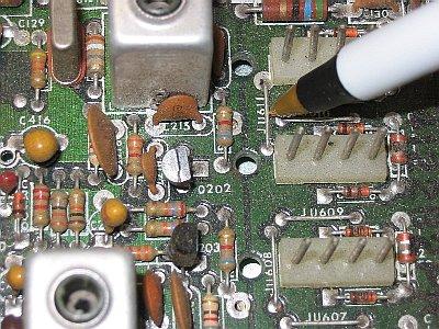
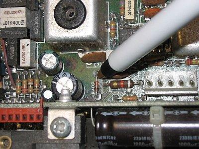
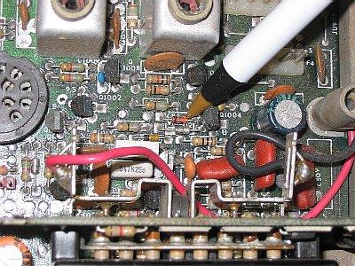
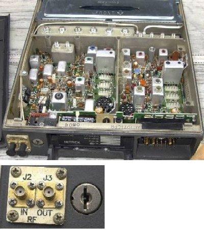
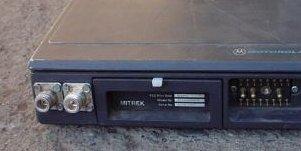
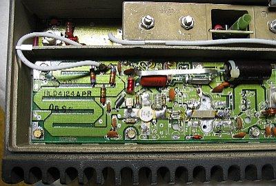
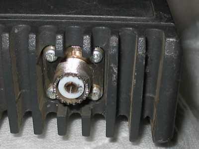
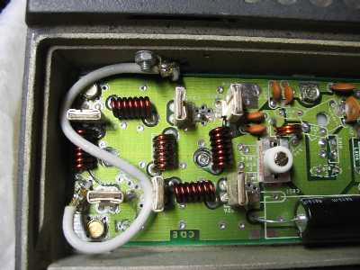
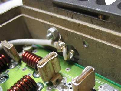
An addition to step "D-1" above that also adds a PTT indicator to the front of the Mitrek (for those folk that don't use a control head) is to cut the two antenna relay coil wires at the back of the relay (instead of disconnecting them from the main board), and then hook them to a red LED and current-limiting resistor in series, and push the LED into a snug fitting hole drilled into the front panel of the radio. The top right corner of the serial number tag is a good place for the LED - there's just enough room inside the chassis for two or even three LEDs vertically along the right side of the handle... One could be a green LED for a power indicator, a red one for PTT... (or a single two-color-three-lead LED for both). To locate the LED holes just latch the handle up and in place (as if the lid was on and the radio was in it's tray) and drill the top hole in the pocket formed by the top right corner of the handle. Watch where the metal chips go, a good start is to drill the radio front panel with the radio upside down on the bench.
Another take on duplexing by N3EUA, now KBØG, can be found at the TAPR website at
http://www.tapr.org/kb0g.html. It's oriented towards packet but it's still relevant.
UPDATE: TAPR has reorganized their web site and dropped a lot of material prior to 2020. Fortunately the WaybackMachine (archive.org) has a copy here at the bottom of the page.
Status Indicators
I used a single freq control head, and for status indication I mounted
LEDs in the top of the head for COS and PL decode. I replaced
the two incandescent bulbs in the head (power on and PTT) with green
and red LEDs just for consistency. This gave me 3 LEDs in the
top of the head: green for power, red for transmitter PTT, and a
three-wire red/green for COS and PL decode. Someday I may add
a blue LED for PL encoder disable (that feature was added to the radio
after the control head work was complete). On an incoming signal
without PL the dual LED glows green, and if PL is present it momentarily
glows green showing the presence of the carrier, and when the PL decodes
the red comes on with the green making amber to make it evident that
both are present. There is no reason I used a 3-wire 2-color LED
except that I had a few in the junk box. Two individual LEDs for
COS and PL decode are just as easy. The PL decode signal from the
one-jumper mod above (JU6 to JU1) is a logic level as opposed to an
open collector, I added an open collector driver transistor in the
head to drive the PL decode LED. I showed the open collector
transistor in the PL decode section above as that's how the most
recent radio was done.
The resistance rule of thumb for a 10ma LED is 100 ohms per volt, so a 1.2k resistor in series with each LED is just about right for 12-13v, but the value is not critical - a 1k or 1.5k will work just as well. For 20ma leds (the most common) use 50 ohms per volt, so 560 or 620 ohms is appropriate. For 2ma LEDs I use 4.7k or 5.1K... Whatever value you pick, use that value on all the LEDs so the light intensity is the same - except on the blue LED. One characteristic of blue LEDs is that most of them take a little more current for the same intensity (they are not as efficient). To compensate some manufacturers use a larger chip in the LED package, some use two chips, either way, you may have to use a little less resistance to get the blue to look right. This is one place where an old Heathkit or Eico resistance substitution box comes in handy.
Mounting
To mount the radios in the system rack cabinet I bolted together a
"sandwich" of two Mitrek mobile mounting trays and a steel rack
shelf we found in surplus. On the top of the shelf is the
transmit radio, under the shelf is the receive radio upside
down. An Astron SS-25M power supply is mounted adjacent
to the transmitting Mitrek, and a control head bracket is bolted
below to complete the assembly. The sizing is perfect,
you'd think that Astron designed the SS-25 specifically to fill
the leftover space in the rack shelf. The Astron is
mounted to the shelf with long tie-wraps that extend through
two holes drilled in the tray (at the "X" in the diagram below),
across the bottom of the shelf, around and up the right side
and back across the top of the supply. Yes, I could have
opened the Astron and drilled a couple of holes in the bottom
to mount it, but I didn't want to affect the warranty, and I
wanted to be able to swap it out without having to pull the
rack shelf out of the cabinet.
When lifting the assembly with a hand on each side the shelf started to "bow" in the middle due to the weight, so I added two pieces of right-angle steel stock, one at the front and the other at the rear of the shelf, both running the full width of the shelf. After the front angle bracket bracing was in place I found it was tall enough that I could no longer get the lower Mitrek in or out of the tray, or to access the control head controls or view the LEDs. The cure for that was to add spacers between the tray, the head, and the rack shelf. The spacers that I used are 1" long pieces of half-inch EMT conduit (only because I had a short length left over from a remodeling project) - lengths of a dowel (even a broken broom or rake handle) with a hole drilled in the center or even stacks of washers would work just as well. Next time around I'll use a stronger steel rack shelf, but we were on a deadline and were forced to make do with what we had immediately available.
The rack shelf I used has side walls that are the exact height of the Astron, and I used a couple of leftover riot handcuffs to hold it in place (the flex cuffs are essentially 18 inch long, wide, thick, extra-strong tie-wraps). The control head bracket is mounted on shorter spacers, the speaker bracket is mounted behind the control head and uses no spacers at all. The spacers between the head bracket and the shelf are just enough to adjust the volume and squelch and to view the LEDs. The speaker fits into its bracket and is held with thumbscrews - by twisting them very tight the speaker lies flat against the bottom of the shelf facing downwards and doesn't budge.
Front view:
  +------ rack mount shelf ears and mounting holes -------------+
  !                                                             !
+---+ +------------------------------------+ +--------------+ +---+
! O ! !                                    ! !   Astron     ! ! O !
!   ! ! transmitting Mitrek mounting tray  ! !   SS-25M     ! !   !
!   ! !          and radio                 ! ! power supply ! !   !
! O ! +----+--------------------------+----+ +--------------+ ! O !
+---+------!--------------------------!-----X---!----------!--+---+
        spacer - see text          spacer     spacer    spacer
      +----+--------------------------+----+ +--+----------+--+
      !                                    ! !     Mitrek     !
      !   receiving Mitrek mounting tray   ! !  Control head  !
      !   and radio (mounted upside down)  ! ! bracket & head !
      +------------------------------------+ +----------------+
Side view - control head and speaker not shown:
Front           Top          Rear
++-----------------------------\
!!                              \
!! <--rack ears                  \
!!                               !
!!===============================! <--transmitter mounting tray (facing up)
!!-------------------------------+ <-- rack shelf bottom
===  # <--spacers -----> #     === \
!    #                   #       !  <--Angle bracket, horizontal part at the top
!    #                   #       ! /
  =============================== <--receiver mounting tray (facing down)
  +-----------------------------+
  !                             !
XX!       Receiving radio       !
  !    (mounted upside down)    !
  +-----------------------------+
The XX at the front of the receiving radio represents the control cable connector and the front antenna connector.
Second Receiver Concerns
There may be times when you want to put a second Mitrek-based link into your
system, or perhaps you already have an existing radio with a 10.7 MHz IF in
your rack. If you keep the lids on your Mitreks, and practice good RF engineering
then 99% of the time this will not be a problem. The once-in-a-great-while
situation can be solved the way Moto did it in the MSR-2000
repeater. The Motorola MSR2000 and the Mitrek share a common
history. In fact you could really stretch and say that the MSR is
what you get when you mix a Mitrek mobile and a MICOR station. Or
you could say that the MSR is a MICOR repeater with Mitrek-derived RF
assemblies. While the Mitrek is a single-board "unified chassis"
design, the MSR uses separate receiver and transmitter boards, a control
shelf, and other non-mobile features. Despite this there are many
common components. One of these is the receiver IF crystal
filters. The normal Mitrek and MSR-2000 IF frequency is 10.7 MHz,
with low side injection. When there is a second receiver in the
same cabinet the second receiver IF needs to be moved to a different
frequency to avoid in-cabinet interference. If you put a second
Mitrek based link in a system cabinet and have an interference problem
you can move the IF of the second receiver by installing the MSR-2000
second IF 10.8 MHz filters, re-ordering the channel element crystal for
a 10.8 MHz IF, and realigning the receiver IF. The part numbers
for the 10.8 MHz filters are (thanks to WA6KLA for the information): Y201
is a 4884396K07 and Y202, Y203, Y204, Y205, Y206 are all 4884396K06. If
you do convert a Mitrek to a 10.8 MHz IF PLEASE leave a note inside the
radio and on the front of the radio - maybe use a big Sharpie pen on
the sides of every IF can and write "10.8 IF". The next guy who
gets to recrystal that radio will appreciate it!
But DON'T go to all the trouble of moving the IF of the 2nd receiver until
you try it in the rack. Mitrek housings are very "tight" and you may not
have any problem at all. This paragraph is here only for the 1%.
Cooling
It has been said often by others, but it bears repeating: A fan doesn't
cool anything; it simply moves air. It may not be worthwhile to install a
fan when the repeater environment is very hot - it will blow hot air on the
equipment. So chose your environment and try to provide cool(er) air for
the fan to move. At some sites I have seen racks with forced air cooling:
a blower in the bottom of the rack and vent holes in the top. The blower
sucks air in the bottom and pushes it up through the rack and out the top.
The blower is controlled by a fan control output on the controller. Some
sites are really dirty, and the blowers suck up fine dust and spread it
through the rack. At one site I saw an air conditioning filter slid into
aluminum channel bolted on the bottom of the rack (which was on 2" casters).
Cooling of the intermittent duty mobile RF power amplifier is critical if you want it to last in repeater service. One trick is to remove the silver shield covering the PA and use a hole saw to cut the top cover of the radio so that a cooling fan can blow cool air directly onto the PA output transistors. Here's a crude drawing that I hope gets the idea across:
                                  air inlet
                              ===finger guard===
                              +----------------+
                              !      fan       !
                              +----------------+                ===finger guard===
  +------------------------------!          !---------------------!            !-------+
  !  Top cover plate             !    air   !                     ! air outlet !       !
  +------------------------------!     !    !---------------------!            !-------+
  ! !                                  V                                ^            ! !
  ! !                                  !                                !            ! !
  ! !                        air flow  +--->---->----->----->----->--->-+            ! !
  ! !                                             PA transistors                     ! !
  ! +--------------------------------------------------------------------------------+ !
  +------------------------------------------------------------------------------------+
Use one hole to mount the fan and finger guard and another hole (with a second guard) for the air outlet. Make sure the guards are gounded (use star washers between them and the cover plate). If you are in a really dusty site you will want to add an air filter above the finger guard on the fan. Finger guards in a variety of sizes are available at your local PC hardware shop, or from a number of suppliers on the web. Welded wire finger guards pass more air than window screening, while maintaining shielding. Or use a piece of copper wire screening, available at most model aircraft hobby shops or from Georgia Copper. And use a good fan - cheap fans use brass or bronze bushings, cheaper fans use plastic bushings, good fans use ball bearings and are worth the extra money. Fans with needle bearings are even better (i.e. mil-spec quality) but not too common and when found are usually prohibitively expensive. Mount the fan to push air into the box rather than to pull air out of it - the push method results in better cooling.
A few tips on fans:Many fans use a driver circuit inside that can create RF hash (especially when right next to a transmitter power amplifier) - so you may want to test your fans by placing a whip antenna on a spectrum analyzer... Key up with the HT and make sure you have a single spike on the screen. Then while still watching the spectrum analyzer power up the fan and see if it is noisy by itself. If not, key up with a handheld next to the running DC fan and see if the commutator chip acts like a mixer or an intermod generator... best you find out if your fans are broad band grunge generators before you drill holes and mount them... This is especially true of those fans with temperature-controlled variable speed controls. If you have a dual band handheld run the test using both bands. If you have access to a low band or 900 MHz radio you may want to duplicate the test using that RF source as well. Why? You may be building a 2m repeater, but the rack next to yours may be a 330w or 500w paging transmitter - on anything from low band (33 MHz to 43 MHz), or high band (151 MHz to 158 MHz) or UHF 451 MHz to 473 MHz) or on 900 MHz (939-941 MHz)...
Next you need to chose between AC or DC fans? Mitrek mobiles are 12vDC radios, and the tabletop base stations are mobiles internally, and some even had a +12vDC battery backup option. Many folks build up 12vDC only repeaters, then put large battery banks on them (the "8D Caterpillar battery" lead-acid batteries used in bulldozers are favorites). Others just plan on having a AC mains powered repeater using an Astron or similar power supply and no battery. Others use an Astron with the float mod (see the Astron page at this web site) and a deep cycle golf cart battery.
There are cases where something in the transmitter is microphonic and you hear fan noise on the carrier. One way to test whether it's mechanical noise being conducted to a microphonic part or electronic noise on the power buss is to disconnect the fan power for a moment (stopping the fans from rotating (with a pencil, or even your finger) does not work as that leaves the commutator circuit operating). If the buzz stays there, it's electronic, if the buzz goes away, it's mechanical. The quick way to solve mechanical noise is to "float" the fan on rubber bushings or on rubber grommets. The right way is to find the microphonic component(s) and fix it(them).
Many DC fans are notorious for creating DC noise and sending it back up the +12vDC power lead, and if you don't have any decoupling components you will hear it in the transmit audio. Unless you are building a purely battery-run system, the simplest way to avoid fan hash on the power buss is to use only AC motor-based fans (or put the DC fans on a separate power supply - a leftover 12vDC wall transformer is a favorite).
If I am going to run the fans off the same source as the radio, my personal
rule is to always assume that the fans will add noise to the DC buss and put
a decoupling network in series with the power to each fan with a choke in series,
and both a 50 µf or 100 µf electrolytic cap and a 1000pf
or .01 µf bypass cap in parallel. See the notes above (in
the section titled "Adding chokes in the leads to the outside world") on making
your own chokes. Mount all three components right at the fan
terminals ‑ no sense in having the fan wiring act as a transmitting
antenna (which is why you do not have just one decoupling circuit - you put the
decoupling circuit on EACH fan). The reason for the small value cap is
that most electrolytics are essentially open circuits at RF. The
electrolytic cap handles the low frequencies and the small cap handles the
high frequencies. See the decoupling networks below:
                                                  +--------+
+12DC -----+-----()()()()--+------------+---------! +      !
           !     RF Choke  !            !         ! 12v    !
           !               !+           !         !        !
           !              ---(big)     ---(small) ! First  !
           !              ---(µf)      ---(pf)    ! DC Fan !
           !               !            !         !        !
           !               !            !         !        !
           !               +------------+---------! -      !
           !                            !         +--------+
           !                           gnd
           !
           !
--- if multiple fans, duplicate the decoupling circuit on each fan...
--- if the above still has noise on the DC line try this method... it
--- uses a second choke per fan, but I've never had this fail...
           !
           !
           !                                      +--------+
           +-----()()()()--+------------+---------! +      !
           !     RF Choke  !            !         ! 12v    !
           !               !+           !         !        !
           !              ---(big)     ---(small) ! First  !
           !              ---(µf)      ---(pf)    ! DC Fan !
           !               !            !         !        !
           !               !            !         !        !
           !  +--()()()()--+------------+---------! -      !
           !  !  RF Choke                         +--------+
           ! gnd
           !
           !

     To additional
     fans (if any)
If you are luckier than I was, your fan(s) is / are
electrically quiet, and you've wasted fifty cents worth of components
per fan. What's your R&D and construction time worth? Or
the gasoline to make yet another site visit because the fan puts
grunge into the transmit audio ? And if you use a thermostatic
fan (or fans), make sure you do the above-mentioned grunge test at
all the fan speeds. Just use a hair dryer to warm up the
thermostat and fake it into thinking the heat sink is hot.
Fans in general can be dirt and dust induction devices... and that can cause a few problems... depending on its composition a thick layer of collected dirt and / or dust can act as an electrical conductor or as a thermal insulator (or both), neither of which is a good thing. Unless you need forced air cooling it's a good idea to not use it. It's interesting that many Moto MSY, MICOR and GE MASTR II stations use massive vertical-finned heat sinks, and convection cooling. Even the tube type high power units (250 watt, 330 watt or 500 watt) use conduction cooled tubes and even bigger convection heat sinks. And no fans. Moto learned their lesson with the BBY squirrel-cage blowers.
A trick that can be used if you do not need a lot of air movement is to use a 24vDC fan on 12vDC, or a 240vAC fan on 120vAC. It will run fast enough to move air, and will last a LONG time.
You can also have a two-speed fan system by using DPDT switching
to convert two fans from series (slow and quiet) to parallel (fast
and loud). While DC fans are shown, the technique works with
AC mains voltage fans as well (just replace +12vDC with 120v, and
GND with Neutral). See below:
+12vDC-----+-------------------+
           !                   !
         Fan #1                !
           !                   !
           !                   !
           !                   !
           !                   !
           !         O------+  !
           !        /       !  !
           !       /        !  !
           !      /!        !  !
           +-----O ! O-+    !  !
                   !   !    !  !
                   !  GND   !  !
                   !        !  !
                   !        !  !
                   ! O------+  !
                   !/          !
                   /           !
                  /            !
           +-----O   O---------+
           !
         Fan #2
           !
           !
          GND
The above fan speed circuit is shown as a DPDT switch, but can just
easily be a DPDT relay with the coil driven by a thermostatic switch.
Design your rack mounting assembly with an eye to allowing air flow to and from the PA fans mentioned above and to keeping the rear heat sink cool... In most Mitrek systems that run a high duty cycle good cooling air flow across the rear heat sink is mandatory, and that usually means a rear fan. Personally I use two thermostat-controlled fans on the heat sink, one set 15, 20 or even 25 degrees higher than the other, and if (or when) the hotter one turns on it also turns on a digital input on the controller, which announces (something like) "over temp on south link transmitter" and changes the pitch on the system MCW ID. If the users miss the voice announcement then the change in IDer pitch gets the regular users attention within the first 10 minutes of dialing up the channel.
The hookup:
(the two capacitors and chokes per fan mentioned above are not shown)

+12v ----------+-------+----+--------+-------------+
               !       !    !        !             !
               !     first  !     second       optional
               !     rear   !      rear        resistor
            PA deck  heat   !      heat           and
              fan    sink   !      sink        "fan on"
             motor    fan   !       fan           LED
               !       !    !        !             !
               !       !    !        !             !
          /    !       !    !        !             \
         /     !       !    !        !             /
        /!     !       !    \        !             \
     +-O ! O---+       !    /        !             /
     !   !             !    \        !             !    +----------------- to controller
    gnd  !             !    /        !  200v 1a    !    !                  logic input
         !             !    \       --- diode or   !   --- 50v 100ma       (active low)
    -----)             ! optional   \ / at least   !   \ / is overkill
         )             ! resistor    V  twice as   !    V  here
  reed   )             !   and      --- large as   !   ---
  relay  )             ! "fan on"    !  necessary  !    !
   ------)             !   LED       !  to carry   !    !
                       !    !        !  fan motor  !    !
 (optional)            !    !        !  current    !    !
 Connect               +----+        +-------------+----+
 reed relay            !             !
 in place              !             !
 of antenna       thermostatic     thermostatic switch #2
 relay so            switch #1    (15-20-25 degrees higher)
 fan runs              !             !
 while                 !             !
 transmitting          +------+------+
 (a low current               !
 fan can be run               !
 directly)                  ground
While the PA deck fan motor is shown connected to the antenna relay circuit that is only an option. You may want to run the PA fan and the heat sink fan in parallel. Or you may want to run the heat sink fan off of a fan control board, and the PA fan off of a controller timer.
The thermostatic switch(es) are mounted using 4‑40 hardware. One method is to drill and tap a heat sink fin and mount them with a drop of white heat sink compound between the fin and the switch body.
The Digi-Key 317‑1094‑ND is a normally open device made by Cantherm, their part number R2005015. It closes at 50 degrees Celsius (about 122 degrees Fahrenheit) and opens around 38 degrees C (about 100 degrees F. It will run you about US$9. Use of a 120 degree device makes sure that the fan(s) do not run unless they have to, but will run to save the transmitter. There are several temperatures avaialable in the Digi-Key catalog in case your environment situation dictates a different trigger temperature,
Another method of fan control is to use a 555 (or a CMOS 555) timer chip triggered by the PTT, and staying on for a time period after unkey. This idea can be extended by adding a thermistor mounted to the heat sink (on the hottest spot) and incorporating it into the 555's timing capacitor charging circuit so that as the heat sink gets hotter the timer takes longer to shut off the fan. The idea is to design a fan control with a similar thermal profile as the transmitter's heat generating parts and the heat sink in mind, and to control the run-time of the the fan enough to extend the transmitter life while not wearing the fan out un-necessarily. If you get occasional kerchunks you can save the fan by not switching it on until the transmitter has been keyed for a finite amount of time - maybe set the threshold at somewhere between 30 seconds and a minute.
An alternate way of controlling the PA deck fan is provided by some repeater controllers: a digital logic output can be programmed to turn on with the first keyup and stay on for a programmed time period after the last transmission. Most controllers use an open collector (or the FET version) and a 5vDC relay coil to +12, with the appropriate snubbing diode is all that is necessary. If you are using AC fans then an opto-isolated solid-state-relay (SSR) can be used. As to the repeater controller programming, well, the Scom 7K programming manual gives a fan control function as one of their Digital Output programming examples. You can extend the example programming by adding a second timer before the first, and preventing the fan from turning on until the transmitter has been on for a specific minimum time (like the 30 or 60 seconds mentioned above).
Some people consider solder to be a preferred programming language - they can use a repeater fan control circuit such as this one, designed by Robert Shepard KA9FLX.
Closing notes
The dual Mitrek assembly described above is currently used as a single
channel full duplex UHF point-to-point link in our UHF repeater
system. The main repeater is on the primary port of the repeater
controller and the dual Mitrek is on one of the other ports. The
reason for the use of dual radios is that the initial implementation
used 450‑470 MHz Mitreks tuned to the regular user input and
output frequencies (443/448 MHz) of the far-end repeater. Later on
one radio on each end was replaced with a 420 MHz Mitrek. The final
configuration had both sets of radios on real link frequencies (around
420.xxx MHz one way, 439.xxx MHz the other).
Watch C800L in the PA deck as you tune up the UHF transmitter. The RF voltage across it is enough to arc over if mistuned and all it takes is one momentary "click" or "pop" to toast the transistor (yes, I've heard it - twice). And the funny thing is that it will work just fine for anywhere from a month to 6 months after the "click" or "pop", then it will rapidly die. The tuning instructions are NOT clear on this, you MUST turn the power control all the way down, and even mistune the exciter output way down before you diddle C800L the first time on the new frequency. Then once it's resonant you can start dialing the power back up. The tuning may change a little as the power goes up, just rock it VERY SLIGHTLY each direction to keep it in tune as you bring the power up in multiple steps. Don't rock it very far or you will hear the dreaded "pop".
If you do pop the PA deck, and chose not to fix it, the radio can still be used. Take the exciter output and jumper it to the RF connector that you are using for the transmitter. You will find that you have about 1 watt on channel. This is enough for a garage repeater (i.e. for controller programming testing), as a point-to-point link radio, or it can drive a MICOR or MSR2000 PA deck, or a TPL, KLM, Crescend, Henry or Mirage repeater amplifier. And if you use a continuous duty PA deck or amplifier the entire assembly will run key-down forever.
Setting the receiver on frequency can be a bit tricky as the Mitrek uses a quadrature detector rather than a ratio detector or a crystal discriminator, therefore there is no "Motorola standard metering point #4" zero-center test point. The Mitrek designers added a circuit (enabled by a jumper on the main board) to help tune with a zero-center meter, but I've found that using a SinAdder gives me better results. I first set a generator on 10.7 MHz (or 10.8) and verify the IF and detector tuning (on a radio fresh from commercial service I've never had to touch it). With the generator set to the operational frequency I use a frequency counter with the hot side of the test probe hooked to pin two of the channel element socket to set the injection frequency (just remember to compensate for the 10.7 MHz (or 10.8 MHz) IF frequency), then do the final channel element frequency set with the Sinadder.
Since both sides of the Mitrek (and several other Moto radios) speaker circuit are hot, remember that any audio test equipment (such as you would use to make a quieting measurement) must be on the far side of a 1:1 audio transformer that can handle a watt or two. Your local high-end car stereo shop or a web-based seller are possible sources of these. I personally use www.crutchfield.com for car stereo stuff - I've made several purchases there and am totally satisfied. In a pinch you can put a 8-16 ohm load resistor (use a 2-5w resistir) across the speaker leads and a 600-600 ohm transformer, or two audio transformers back-to-back or a 400 Hz aircraft power transformer - see the text above.
Remember that the Mitrek mobile transmitter was not designed to be a 100% duty cycle transmitter. In fact, Motorola states in the manual that the Mitrek is a 20‑25% duty cycle radio. This means 20 to 25 seconds maximum out of every 100 seconds. Mobile radios have inherently undersized heat sinks, so to keep the heat rise down and your transmitter alive make sure you keep the output power at no more than half of the rated output (the lower the heat produced the better, but they get dirty and squirrely if run too low in power).
Personal opinion: The manual says 20‑25% duty cycle, without a qualifier for high power models. I consider the low power radios (model numbers with 31, 32, 33, 34, 41, 42, 43 or 44) in them to be 20‑25% duty cycle, and the high power radios (those with 51, 52, 53, 54, 61, 62, 63, 64, 71, 72, 73, 74, 81, 82, 83 or 84 in them) to be a 10% duty cycle. Other folks will disagree, I have seen a 74 series with dual fans run in repeater service for several years, and that group has a weekly net that runs the transmitter continuously for 2 1/2 to 3 hours. Frankly the MICOR, MSR2000, MSF5000 or GE Master II or Master III continuous duty stations (real repeaters with BIG heat sinks) are much better suited for this job.If you have your heart set on a Mitrek-based radio then look at the MSR2000 station - it is a cross between a second generation control system card cage (based on the one from a MICOR station) mated to a Mitrek-based exciter and receiver and comes in both intermittent duty and continuous duty models. And remember, the transmitter efficiency goes DOWN with frequency: A high band transmitter runs hotter then equivalent low band transmitter of the same power output range, and a UHF one runs even hotter. A 900 MHz paging transmitter makes a better space heater than a transmitter (especially the 350 watt or 500 watt output ones).
Back to Mitrek mobiles: The low power radios (20-30 watt) are preferred for repeat / link / beacon service - even a low power radio at half power is more than enough to drive an external amplifier to whatever power level you can afford. And point-to-point links can use directional antennas... 15w into a 10 dB yagi gives the same performance as 150w into an omni with a lot less transmitter, power supply, and duplexer required... If you need a radome for antenna protection a UHF yagi will fit inside a piece of large diameter PVC or ABS waste line pipe (but the plastic CAN affect the tuning, so check the SWR before and after installing the pipe). Fiberglass pipe is preferred, but comes at a higher price. No matter what pipe you use make sure the antenna mounting can handle the "sail" effect and not twist in the wind, or bend with a load of winter ice.
Opinionated comments: (at no extra charge)
Consider doing the transmitter tuning with an eye on a spectrum analyzer - remember that a dummy load accepts all manner of frequencies without complaint, being non-resonant by design, while a tuned circuit (like an antenna or duplexer cavity) will complain about harmonic content and spurious output. To quote WB6VYX's comment on spectrum analyzers "A picture tube is worth at least 20 dB of clean..." A transmitter that is not producing clean output will not behave on a hill and sooner or later WILL cost you your site and give amateur radio yet another black eye. Analyzers are also useful in tuning a local oscillator / multipler chain - years ago I was tuning up a high band Motrac and could not get a proper peak. I plugged a Tektronix scope probe into the spectrum anayzer and poked around the problem stage and discovered that a previous stage was tuned up on the wrong harmonic. You can also use the spectrum analyzer to get true interstage peaks - on adjustments that appear to have very broad peaks on a meter you can frequently see on an analyzer a magic point within the peak where the spurious low level spikes drop sharply. This trick can do quite a bit in reducing transmitter spurious emmissions and receiver birdies. Yes, once you learn the trick you will find youself tuning receiver multiplier chains with a spectrum analyzer.
Be a good RF neighbor! After you install your radio(s) in the system rack make sure you check the output(s) with a spectrum analyzer - make sure that the transmitter is clean and by all means use a circulator followed by a good quality commercial pass cavity. The web page at N6CA's Repeater Application Note page is well worth reading. RF neighborliness is one place where the UHF MICOR mobile has it hands down over the UHF Mitrek: every UHF MICOR mobile has an internal 100w circulator, even the 25watt models.... and I have seen some MICOR UHF mobile circulators attached to some definitely non-MICOR radios... (just make sure that you follow every hilltop circulator or isolator with a pass cavity - they generate harmonics). Never, ever have a circulator or isolator directly connected to an antenna.
Contact Information:
The author can be contacted at: his-callsign // at // repeater-builder // dot // com.
Back to the top of the page
Up one level
Up two levels
Back to Home
This page originally posted on 01-Oct-2003
Good luck and after you get your Mitrek(s) going please drop me an email and let me know how things went. I've spent a lot of time on this web page and its thirty-plus revisions, and sometimes I'm wondering if anybody reads these missives to the masses...
If you see something above that is vague, missing (or outright wrong), please let me know! It's input from the readers that make these writeups better - I've probably either totally missed or shortchanged topics and /or subtopics that really need to be covered.
Text, photos (unless otherwise noted) and hand-coded HTML are all Copyright © Michael R. Morris WA6ILQ 2003 and date of last update.
This web page, this web site, the information presented in and on its pages and in these modifications and conversions is © Copyrighted 1995 and (date of last update) by Kevin Custer W3KKC and multiple originating authors. All Rights Reserved, including that of paper and web publication elsewhere.
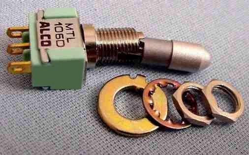