426 West Taft Ave. Orange, Calif. 92865
Phone: 714-998-3021 Fax: 714-974-3420
US & Canada: 800-854-0547 Fax: 800-850-0547
http://www.com-spec.com
| Back to Home |
Technical Information on Products by 426 West Taft Ave. Orange, Calif. 92865 Phone: 714-998-3021 Fax: 714-974-3420 US & Canada: 800-854-0547 Fax: 800-850-0547 http://www.com-spec.com |
E-mail: •
Com-Spec is also the source of the Selectone line of products.
Note: Com-Spec will sell direct
to the end user and can easily beat Hutton's, Tessco's and most others prices.
Call 800-854-0547 or 714-998-3021 from 8:00am to 4:30pm (Pacific time zone), Monday to Friday
If you have any additional info or data sheets that are not included below,
please let us know!
If you can't scan them then we can scan them and return them to you.
Compiled, HTML'd and Maintained by Mike Morris WA6ILQ
Formerly Maintained by Robert Meister WA1MIK
In June 2021 we discovered that Com-Spec is no longer selling any CTCSS encode or decode products. They have a few items on their web page but even a lot of the installation sheets have been pulled from their file system. Even the Selectone CTCSS products are listed as "Not in production" so there's a big void to be filled.
In the land mobile (e.g. commercial 2-way) world, there are (or were) three different companies that used the initials CSI. The most famous is Communications Specialists, listed above, and whose products are on this page. Then there is Connect Systems Incorporated, which made repeater tone panels for the commercial market and autopatch equipment for the amateur market. They are located in Ventura, in Southern California (their previous address, still on the title pages of some of the downloadable manuals, was in Torrance, California) and they have their own web page at this web site. The third CSI company was Communications Systems Incorporated company in Lynnwood WA, which is long out of business. That "CSI" made, among other things, the CSI-32 and CSI Super-32 repeater tone panels that are a blue-gray color. Copies of the manuals are on the "Other Manufacturers" page at this web site. If anyone has copies of other manuals we'd appreciate a chance to scan them.
The three CSI companies are not (and were not) linked in any way
(except in the minds of a few clueless customers).
Click here to jump down to the Selectone products
Com-Spec Data Sheets
Many of the Com-Spec encoder products had a low output impedance which can load down other circuitry when connected. This is not a design fault of the Com-Spec product. Depending on the application it may be necesary to add a series restor between the encoder and the destination circuitry. The value of the resistor will range from 1k to 47k depending on the application.
|
|
Com-Spec 2018 catalog 3.4 MB PDF file |
|
|
Com-Spec 2003 catalog 1.1 MB PDF file |
|
|
DCS-23 Instruction Sheet / Schematic 364
kB PDF file This is a universal DCS encoder/decoder. Think "TS-32" for Digtal Coded Squelch (DCS). The more common name is Digital Private Line (DPL), a Motorola trademark or Digital Channel Guard (DCG), a GE trademark. |
|
|
HP-1A Instruction Sheet / Schematic 200
kB PDF file This is a discontinued product. It was a stand-alone high pass audio filter board similar to the one contained in the TS-32 or TS-64 and is easily duplicatable on perfboard. |
|
|
HP-1B Instruction Sheet 108 kB PDF file This is a discontinued product and consisted of the HP-1A packaged as a hybrid chip (that was manufactured by Murata for Com-Spec), and it is no longer available. |
|
|
TS-64 - 84-7000 "Daniels" Version 635 kB PDF file This is a special version with a daughter board - courtesy Skipp May. |
|
|
ID-8 Instruction Sheet / Schematic 364
kB PDF file This is a generic CW ID board that can be added to almost any repeating radio. See the article by Jerry Matthews on the MICOR or MSR2000 pages. Also see the comparison to the HamGadgets ID-O-Matic by Robert Meister on the Technical Information page. |
|
|
ME-3 Instruction Sheet / Schematic 64
kB PDF file courtesy of Skipp This was an encode only subminiature encoder that used plug-in ceramic resonators that had two pins on the bottom an an ink-stamped tone code on the top. The PC board had a range jumper - if the unit does not produce the correct tone you need to check for the absence or presence of the jumper. There was also a ME-12 version of this that was in a plastic box with a rotary switch on the front and 12 tone element sockets inside. |
|
|
ME-3 Instruction Sheet / Schematic 180 kB
PDF file courtesy of Bob WA1MIK Larger, clearer, original scanned page, converted to PDF. |
|
|
RB-1 Instruction Sheet / Schematic courtesy
of Eric Lemmon WB6FLY The RB-1 adds 180-degree reverse-burst and delayed PTT to ME3s, TS-32s and other encoders. To change the duration of the reverse burst adjust the value of C3 or R13. Here's the same file as a 95 kB PDF courtesy of Eric Lemmon WB6FLY This is a discontinued product but it's easy to duplicate on perfboard. Also, this circuit will work in any system that uses a reed-based decoder and also with some electronic decoders. It may not function with some newer radios because some manufacturers (i.e. Motorola) use 120 degrees phase shift for reverse burst instead of the 180 degrees that this unit provides. |
|
|
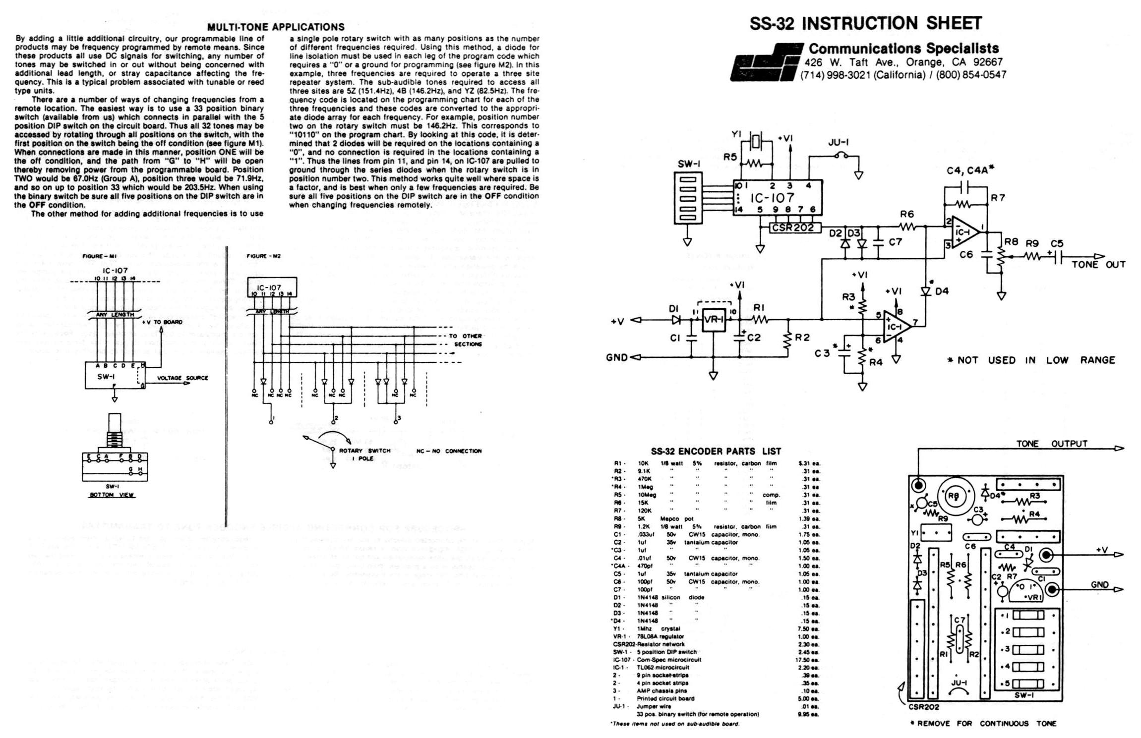
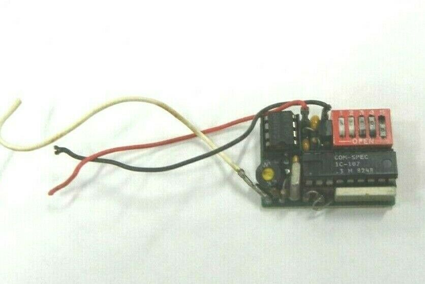
SS-32 Instruction Sheet / Schematic 360 KB JPG Encode only; IC-107 version Photo |
|
|
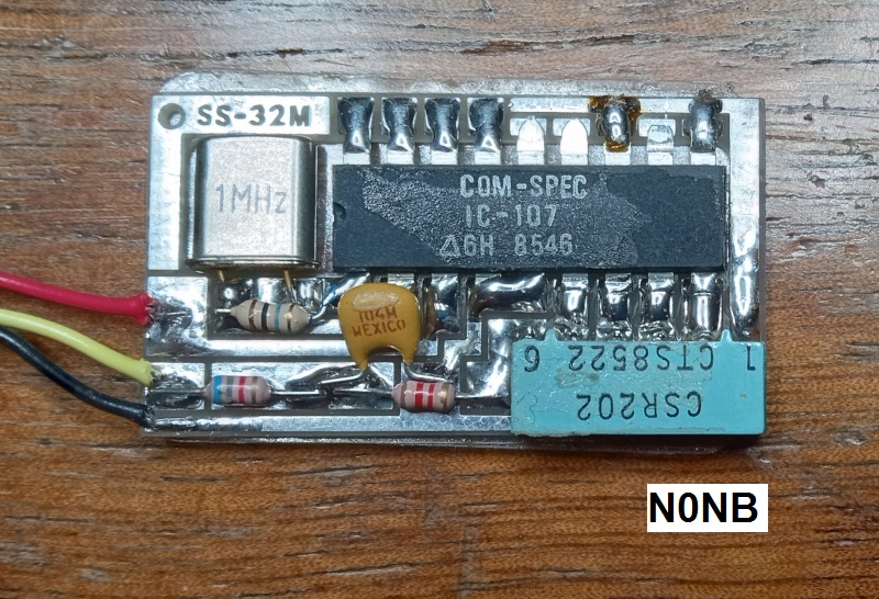
SS-32M Instruction Sheet / Schematic 1.2 MB PDF file courtesy Nate NØNB A later 4-page version
Encode only; IC-107 version Photo |
|
|
SS-32P Instruction Sheet / Schematic 216 KB PDF file Encode only; IC-110 version |
|
|
SS-32SMP Instruction Sheet / Schematic 149
kB PDF file Encode only, very small (surface mount version of the SS-32P) |
|
|
SS-64 Instruction Sheet / Schematic 288
kB PDF file Encode only, with optional reverse burst |
|
|
TE-12P Instruction Manual 220 kB PDF
file courtesy of Chuck NØNHJ Encode only. Uses 12 individual 5-bit DIP switches to select 12 tone frequencies and a rotary switch to select a particular preset tone. |
|
|
TE-16 Supplement (uses SS-64) 450
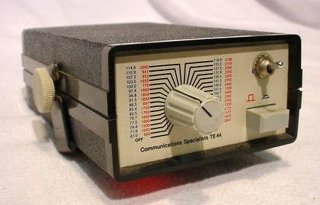
kB PDF file courtesy of Randy Johnson via Greg Beat W9GB Encode only. Uses a 16-position rotary switch to select one tone frequency pre-programmed by the factory. The TE-12P seems to be a much better deal. Perhaps the TE-16 was a less-expensive option. |
|
|
TE-64 Instruction Sheet / Schematic 819 kB PDF
file courtesy of Com-Spec Photo of a non-display unit courtesy of N7FM Photo of a TE-64D display unit courtesy of WA6ILQ |
|
|
TP-38 community repeat panel documentation: This was the predecessor to the TP-3200. The basic unit does not do digital squelch / DCS / DPL / DCG and in the beginning the sales literature said it could not be added. Later on a kit was developed that added it. The TP-38 is a handy unit that decodes any combinations of CTCSS tones and can allow your repeater to decode multiple tones. Just program it for zero hang time, then connect the PTT OUT pin to the repeater controller TONE DECODE IN pin (i.e. as if it was an external CTCSS decoder... which it is). A note from WA6ILQ: Years ago when the Los Angeles area 220 Coordination group decided that all 220 repeaters had to add PL decode a few repeater owners just added TP-38s and programmed them to decode ALL of the tones. When the keeper of the public repeater lists asked the repeater owner what tone he had chosen the answer was "Yes"...
|
|
|
The TP-3200 community repeat panel was the follow-on to the TP-38. Here's all of the
documentation we've been able to find: This unit does all 51 PL/CG/CTCSS codes and 106 DPL/DCS codes. While this is a terrific unit do not plan on using the internal IDer in amateur radio repeaters. The ID code speed is fixed at 25 WPM and can not be slowed down. It is, however a very useful unit that will allow your repeater to respond to any combination of CTCSS tones or CDCSS codes on the input.
|
|
|
TS-32 Instruction Sheet / Schematic 1.9 MB PDF file This is the full 6-page data package containing the schematic, parts list, programming instructions, power connections, receiver connections (audio muting), high pass filter connections, multi-tone information, troubleshooting, etc. IC-107 version. Note that the hangup pin must be grounded or it won't decode. This is the single most common installation error. |
|
|
The TS-32 electronics spawned several other products including several boxed products that used a rotary switch to select the tone. Some just had the switch, some also had a two-digit digital display. Here's a photo of a non-display unit. |
|
|
TS-32HB Instruction Sheet /
Schematic 262 kB PDF file 4 pages. Encode and Decode. Courtesy of Eric Lemmon WB6FLY. |
|
|
TS-32P Instruction Sheet / Schematic 239
kB PDF file 4 pages. Encode and Decode. IC-110 version. Courtesy of Chuck NØNHJ. |
|
|
The Com-Spec TS-32 and TS-64 units are full duplex, but the TX and RX tones must be the same. The PTT logic delays the release of the PTT output so the reverse burst tone is passed before PTT is released; it isn't used to change the board from one mode to another. For full-duplex operation, the "hang-up" lead needs to be grounded so the decoder logic runs all the time. Even the filters run all the time. |
|
|
TS-64 Instruction Sheet / Schematic 300
kB PDF file This is the full data package containing the schematic, tone chart, programming, etc. It can also be text searched. Additional information on the TS-64 can be found here, courtesy of Mike Morris WA6ILQ. Note that the hangup lead (the violet wire) must be grounded or the decode output (the white wire) won't show any indication. This is the single most common installation error. |
|
|
TS-64WDS Instruction Sheet / Schematic 1
MB PDF file courtesy of Com-Spec This is a new variant on the TS-64 that has some differences that make it attractive for repeater stations: it has an audio gate function. |
|
|
TS-64WDS Instruction Sheet / Schematic 978
kB PDF file courtesy of Com-Spec A newer version of the above Instruction sheet. |
Modifications
|
|
Modification of the TS-32 for shorter release time By Bob Schmid of S-Com Industries |
|
|
Modification of the TS-32 for faster response time Information supplied by Com-Spec |
Other Information
|
|
Five Position DIP Switch Table for the
TS-32 and other five-switch models By Mike Morris WA6ILQ This chart has both the "Group A" (subaudible) and the "Group B" (audible) tone tables. |
|
|
Six Position DIP Switch Table for the TS-64 and other six-switch models By Mike Morris WA6ILQ |
Hookup Information
|
|
Generic notes on TS-32 Hookup By Kevin Custer W3KKC |
|
|
TS-32 To GE Master Exec 112 kB PDF file courtesy of Com-Spec |
|
|
TS-32 To E.F.Johnson Repeater 145 kB PDF file donated by James Duram |
|
|
TP-3200 community repeat panel to Motorola MSR-2000 repeater 39 kB PDF courtesy of Com-Spec |
|
|
TP-3200 community repeat panel to Motorola MICOR station 99 kB PDF file courtesy of Com-Spec |
|
|
TS-64 to Mitrek mobile hookup 32 kB PDF file courtesy of Com-Spec |
|
|
Com-Spec also makes a little daughterboard for the TS-64 so it'll plug right onto the P908 pins in a GE MASTR II station (right in place of GEs tone board). Look for the TS-64MSTII on their price sheet. There is a modification article on the TS-64MSTII on the GE page at this web site. |
In 2000 Com-Spec purchased
![]()
and continues to support the products that were current at that time.
Clicking on the logo above will take you to the Selectone products web site.
Note: Selectone used the "DigiTone" and "SmarTrunk Systems" names on some products.
Here are some Selectone products data sheets:
...and if you have any data sheets we don't, please scan them and send them in!
|
|
Selectone ST-100 Tunable CTCSS Encoder 178 kB PDF file Donated by Eric Lemmon WB6FLY |
|
|
Selectone ST-101 Tunable CTCSS Encoder-Decoder 300 kB PDF file Donated by Eric Lemmon WB6FLY |
|
|
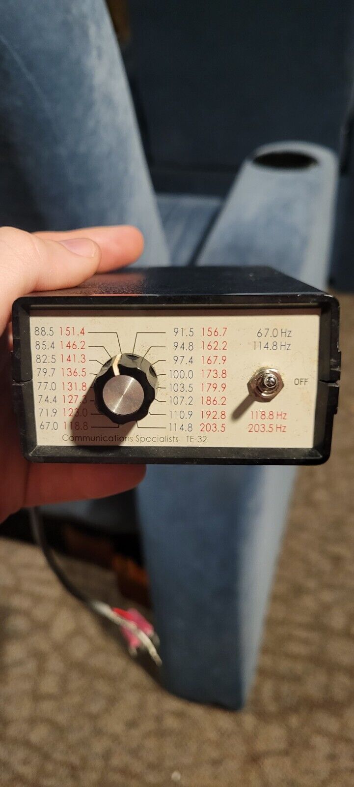
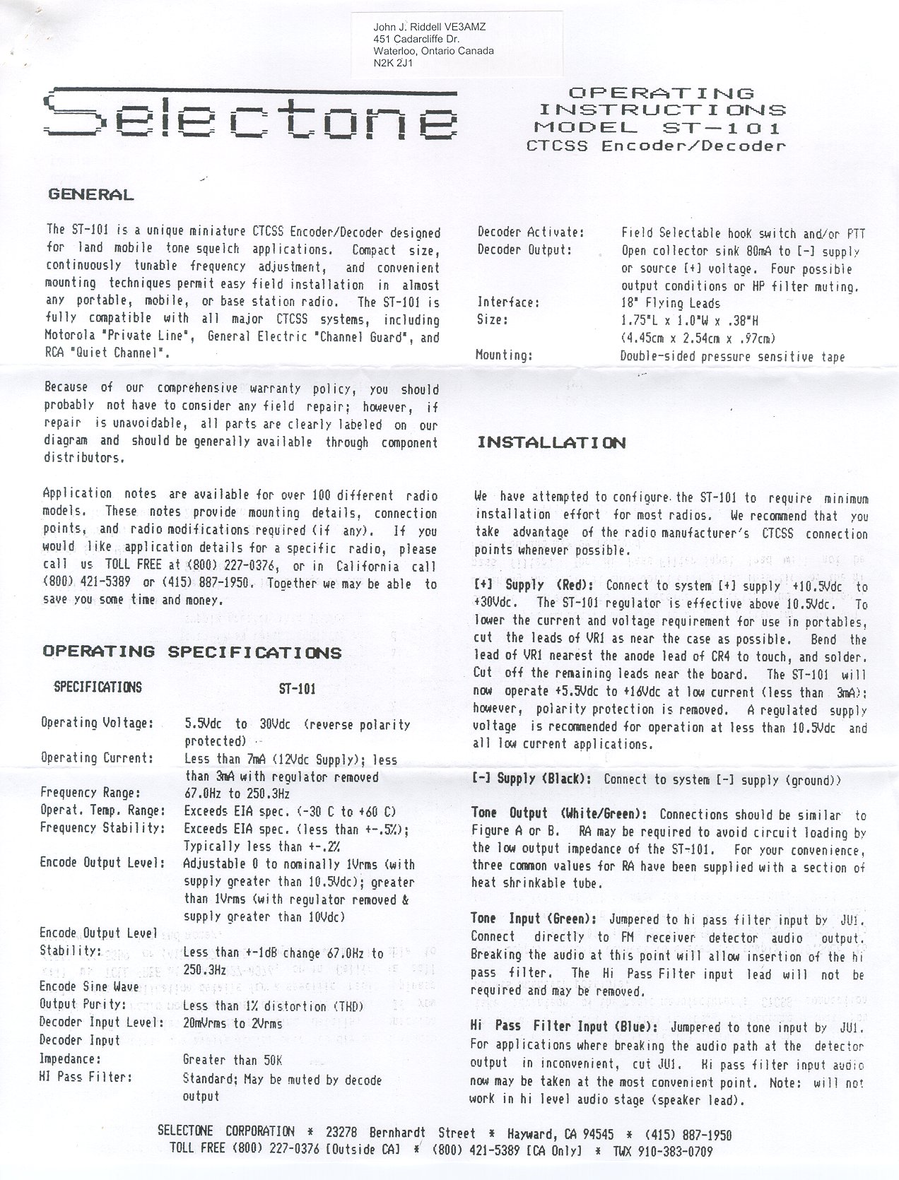
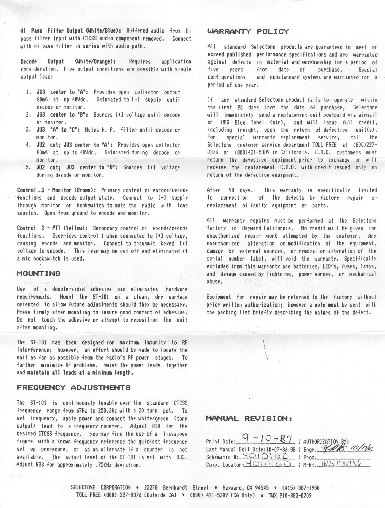
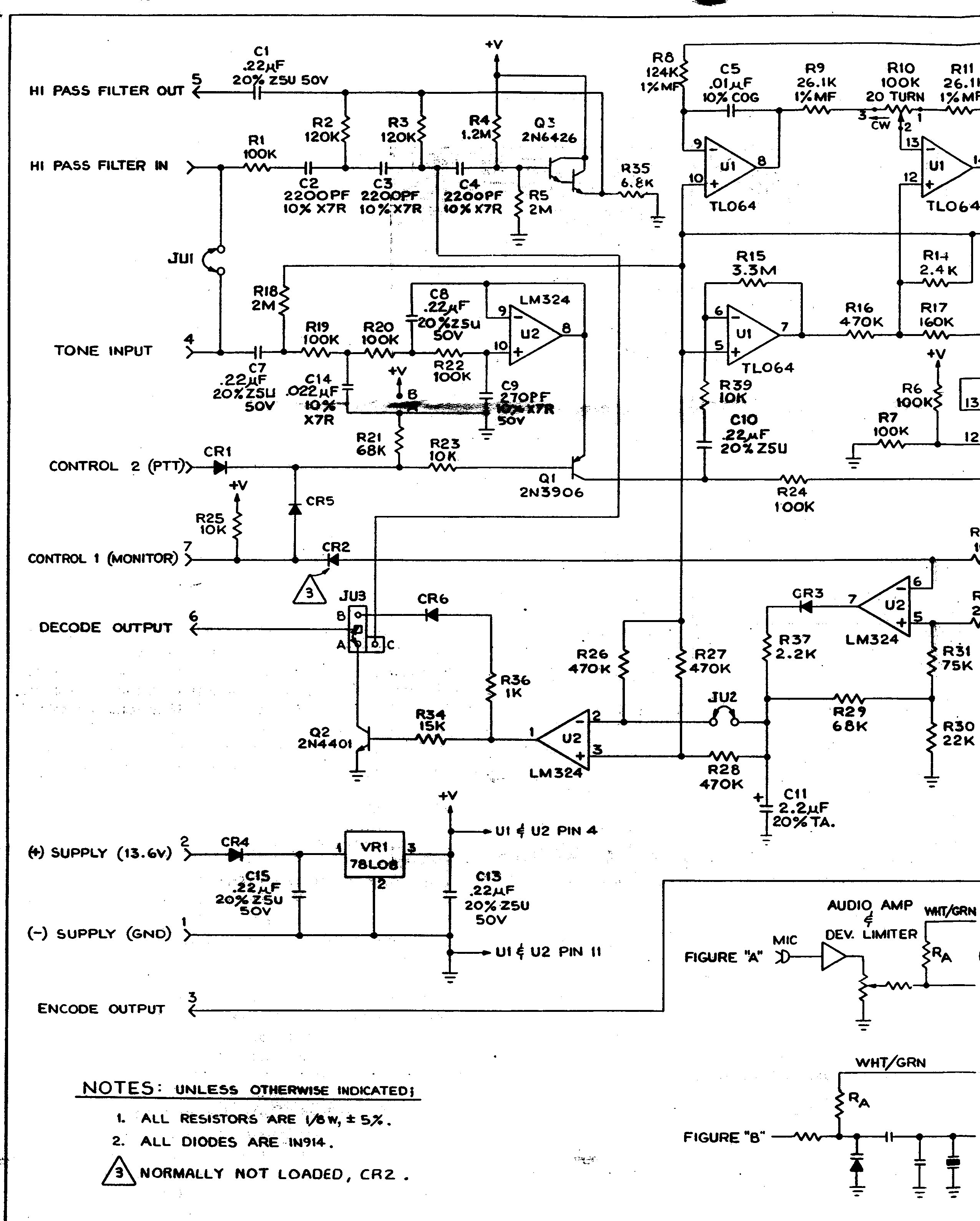
Selectone ST-101 8.5x11 format:
page 1
page 2
page 3
page 4 Tunable miniature encoder-decoder donated by John J. Riddell VE3AMZ. |
|
|
Selectone ST-104 Tunable CTCSS Encoder-Decoder 342
kB PDF file Encoder and decoder with RX PL filter. Donated by Eric Lemmon WB6FLY. Older version of the Selectone ST-104 8.5x11 format: page 1 page 2 Large format: page 1 page 2 Donated by Laryn Lohman K8TVZ |
|
|
Selectone ST-110 354 kB PDF file tunable tone encoder. Courtesy of Chuck NØNHJ. |
|
|
Selectone ST-130 122 kB PDF file DIP-switch programmable CTCSS tone encoder. Second page has a much cleaner programming sheet. This unit seems to be nearly identical to the ST-133 below. Courtesy of Norm Burton KD6AAJ. |
|
|
Selectone ST-133 140 kB PDF file non-tunable, DIP-switch programmed, encode only. MX315-based. |
|
|
MX-COM/CML MX-315 CTCSS encoder datasheet 170 kB PDF file This IC is used by several Selectone and Com-Spec tone boards. |
|
|
Selectone ST-138 124 kB PDF file This encode-decode board was used in some ACC products, and has an RX audio filter. To recognize it look for an MX-355<some letter> chip and a 6-position DIP switch. It is interchangeable with the ST-104. |
|
|
Selectone ST-139 233 kB PDF file A DIP-switch replacement for the ST-146 encoder-decoder. MX-465 based. |
|
|
Selectone ST-140 107 kB PDF file Replacement for the ST-100 encode-only unit. Tunable. |
|
|
Selectone ST-146 263 kB PDF file Replacement for the ST-104 encoder-decoder (with audio filter). |
|
|
Selectone ST-150 (1990) 750 kB PDF file A 1991 version 1.6 MB PDF file |
|
|
Selectone ST-1600 Community Repeater Tone
Panel: All donated by Wes Fay KA7UEC System Documentation 8.5x11 format: page 1 page 2 page 3 Selectone ST-1600 Schematics 8.5x11 format: page 1 page 2 Selectone ST-010 8.5x11 format: page 1 page 2 A carrier control timer module Selectone ST-012 8.5x11 format: page 1 page 2 page 3 page 4 An audio-squelch module |
|
|
Selectone ST-180: Selectone ST-180 Installation and Operation Guide 3.2 MB PDF file Selectone ST-180 Summary 1.6 MB PDF file |
|
|
Selectone ST-210 290 kB PDF
file courtesy of Eric Lemmon WB6FLY This unit is a two-tone sequential decoder, sometimes called a 1+1 decoder. This PDF covers both the ST-210A and ST-210B - there is a difference. |
|
|
Selectone ST-800 Subminiature DTMF Decoder 102 kB PDF file |
|
|
Selectone ST-809B Remote Control DTMF Decoder 189 kB PDF file |
|
|
Selectone ST-954B Programming Adapter
Schematic 38 kB PDF file This serial interface adapter is used with the ST-25, ST-50, ST-804, ST-809, ST-888, and ST-907 Product Manager programming software. |
Back to the top of the page
Back to Home
Web page design, layout, text and hand-coded HTML is copyright © March 2002 and date of last revision by Mike Morris WA6ILQ.
This web page, this web site, the information presented in and on its pages and in these modifications and conversions is © Copyrighted 1995 and (date of last update) by Kevin Custer W3KKC and multiple originating authors. All Rights Reserved, including that of paper and web publication elsewhere.