Up two levels (Motorola Index Page)
Back to Home
The HT600, HT600E, HT800, the MT1000, the MTX800, the MTX900, the MTX Classic and the P200
Written by Mike Morris WA6ILQ
Photos by the author unless noted.
Maintained by Robert Meister WA1MIK

|
Up one level (Genesis page) Up two levels (Motorola Index Page) Back to Home |
An overview of the Genesis series of hand-held radios and their accessories The HT600, HT600E, HT800, the MT1000, the MTX800, the MTX900, the MTX Classic and the P200 Written by Mike Morris WA6ILQ Photos by the author unless noted. Maintained by Robert Meister WA1MIK |
|
This page is a work in progress... If anyone has any updates - manual availablity, parts prices, etc. Or if they would like to contribute any information or photos please contact the author.
Attention eBay sellers and buyers: No matter WHAT the model tag
says, no HT600, HT600E, HT800, MT1000 or P200 will ever do the entire 30-50 MHz,
136-174 MHz, or 406-470 MHz frequency range listed on its model tag or label.
Each radio will do only a portion of that model tag frequency spread, called
a "range", "split", or a "bandsplit". This is a simple law of physics - the RF
engineering technology of the day handn't advanced to the point where the wider
splits were practical (like on the later product lines).
See additional information in the section titled "Frequency
Bands, Ranges and Splits" below.
The Motorola Genesis line of hand-held radios includes the HT600, HT600E, HT800,
the MT1000, the MTX, the MTX "Classic", the MTX800 (800 MHz), the MTX810,
the MTX900 (900 MHz) and the P200 radios plus the matching accessories (note that
Moto Marketing pulled a very bad move - they named both a Genesis-series and a
Waris-series with the name MTX900. The two radios are very, very different). The HT600E
radio is a European version of a MT1000 - as far as I know all they did was change the
label and customize the RSS programming software to European requirements (but the
MT1000 RSS works just fine). The HT800 is a European model, if my source is correct it
is an 8 or 16-channel MT1000 with a 5 Tone paging decoder added. As far as we know the
MTX, the "Classic", the MTX800, the MTX810, and MTX900 radios are all 800 MHz
and 900 MHz - at this time we have no data on them.
One Caution: The HT600 and MT1000 radios are a different voltage from some of the
800 MHz and 900 MHz radios. Some are 10v, some are 12v.
When Moto decided to sell radios through retail outlets under the Radius name they took the HT600 and MT1000, changed the color of the plastic to black, and slapped a P200 label on it - under the covers the high band and UHF P200s are pure HT600. The low band P200 is an MT1000 inside.
All HT600 / MT1000 / HT600E / P200 models are 5 kHz deviation wideband. This means that the 132-174 MHz and 406-512 MHz models will not be legal for use on Part 90 commercial, railroad or public safety frequencies in the USA as of 1-Jan-2013. The 30-50 MHz band, GMRS, MURS and amateur radio are not affected by this. Note that MURS has two wideband channels and three narrow channels. MURS is Part 95, not Part 90, and so the two wideband channels will not be going narrow on 01-Jan-2013.
Update: In April 2012 the FCC amended the mandatory Jan 1, 2013 narrowband change. The 470-512 MHz range will be allowed to operate wideband - but for an unknown amount of time. See order DA 12-642 at https://www.fcc.gov/document/waiver-narrowbanding-deadlines-t-band-470-512-mhz-licensees
Missing info: (contributions of information are welcome!)
1) MTX800, MTX810, MTX900, "Classic" radio information
2) Will the MTX900 go to 902/927 MHz amateur radio channels? If so, how?
Models and Specifications:
HT600:
As far as I know the HT600 was the first radio in the Genesis series, was sold only in
the USA, and did not come in a low band model (these are not the UK / European
HT600E radios). The later MT1000 (see below) had more memory in the microprocessor based
control board, offered up to 99 channels, MDC, and models in the 30-50 MHz range
were available. I do not know if the HT600 or MT1000 radios were made in the 66-88 MHz
range. If they were the frequency range digit in the table below would be a "2".
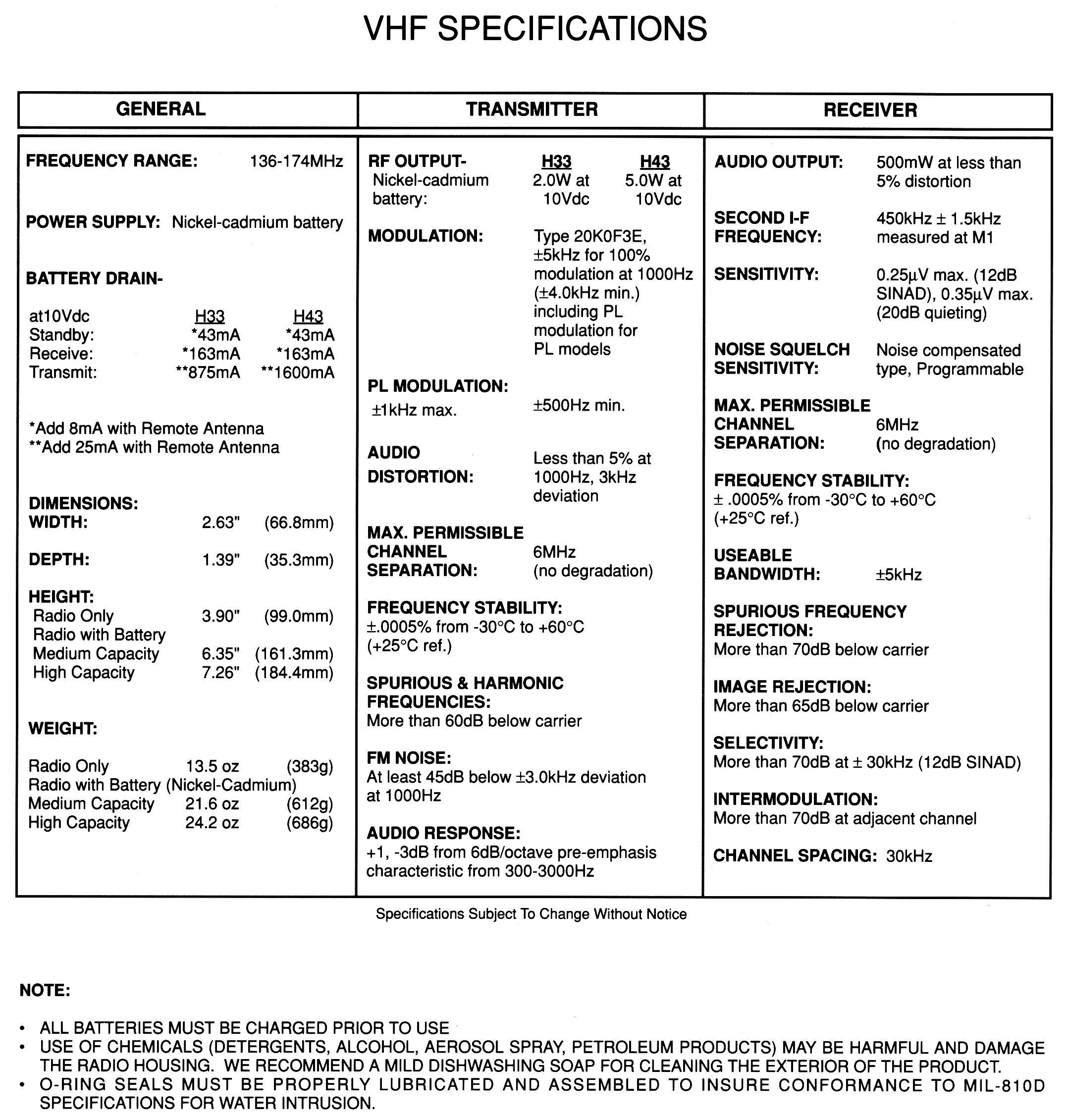
HT600 VHF Specifications page 611 KB
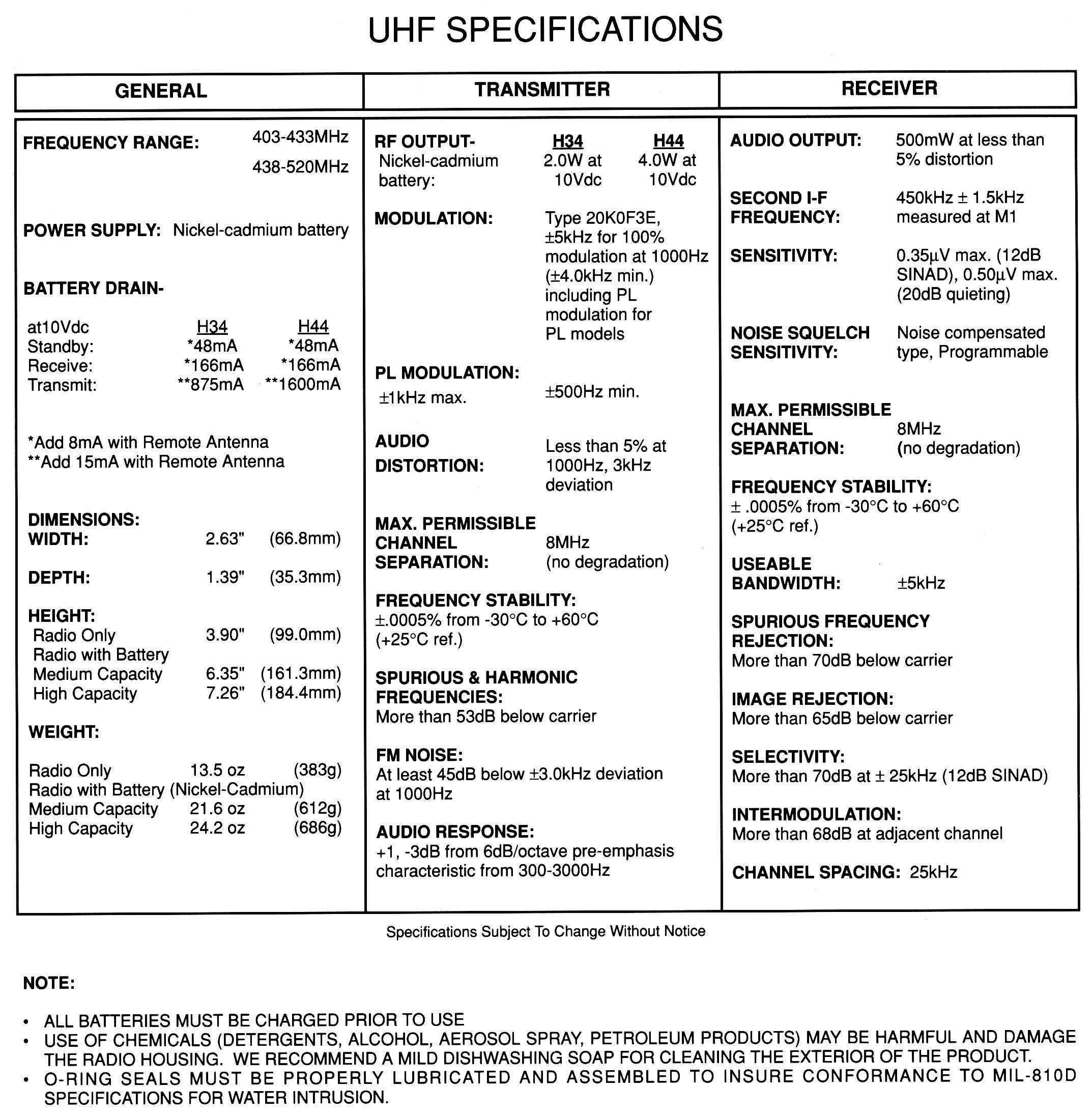
HT600 UHF Specifications page 614 KB
Original HT600 Brochure 957 KB PDF
| Sample model number: H43SVU-7160BN | |||
| H | 4 | 3 | SVU |
| Radio Type |
Transmit Power [1] |
Frequency Range [2] |
Product Line |
|
H Hand- held Z Special Product |
3 136-174 MHz: 2 Watts 403-470 MHz: 2 Watts |
3 136-174 MHz in 3 ranges |
SVU HT600 |
| 4 136-174 MHz: 5 Watts 403-520 MHz: 4 Watts |
4 403-520 MHz in 4 ranges |
||
| Sample model number: H43SVU-7160BN | |||||
| 7 | 1 | 6 | 0 | C | N |
|---|---|---|---|---|---|
| Squelch | Channel Spacing | Channels | Variation | Issue [4] | Packaging [5] |
| 7 PL or DPL |
0 Wideband [3] |
2 2 channels |
0 | A [6] | (blank) (bare radio) |
| 1 Narrowband [3] |
6 6 channels [7] |
B | C Alkaline |
||
| C | N Nickel- Cadmium [1] |
||||
MT1000 / HT600E:
As said above the HT600E radio is basically a relabeled MT1000 with some variations in the
RSS. It is a total internal upgrade and different than the USA HT600 - the control board is
different, some of the RF boards are the same, the HT600 and MT1000 accessories, including
batteries are the same. Friends in the local 2-way community have told me that one or
two HT600Es were shown to police departments here in the Southern California area, but as far
as I know none were ever sold here, and there are no FCC approval numbers on file for a model
called the HT600E. The MT1000 was the name given the radio that was sold in the USA,
and the MT1000 RSS works just fine on the HT600E radios. Around mid-2006 a large
number of HT600E UHF radios were surplused by the UK national police forces. These
were a special version built by Motorola GMBH for the UK Home Office - 2 watt UHF 99
channel Z34GCJ7190 radios that except for the HT600E escutcheon are identical to the
US-made MT1000. Some of them had an encryption board designed by Marconi Secure
Communications division installed inside the radio (MSC was pronounced "mask" and the
option board became known as "the MASC board"). The Z as a first letter (rather
than an H) signifies a "Special Production" model, and I do not know what the exact
differences were other than the MASC board and the large capacity battery shipped with
a low power radio. I would very much like to see some UK-sourced info describing these
UK "Z" radios.
Supposedly the MASC system was developed by the Marconi Secure Radio group, and after
MSR was shut down the products, including MASC, were transferred to the Marconi Secure
Systems division. The focus of the Secure Systems operation was computer network security,
not radio. This situation became worse when the Marconi parent company was sold and
split. Secure Systems ended up with the new Marconi Company, which was basically a
telecomunications and internet company. That was the end of MASC.
There is very little information on the HT600E on the USA side of the Atlantic, and I
was surprised when this file showed up in my email...
HT600E Service Manual 6881050C45-O. This is a 21
page PDF that is 2.15 MB in size. There are several HT600Es on the USA side of the
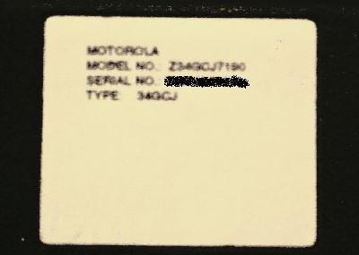
Atlantic, and as far as I know none of them have a serial tag. The first version of this
web page asked for a photo of a HT600E serial tag and this showed up in email:
|
Here is an HT600E Model Number Breakdown for the UK Ex-Police Model Z34GCJ7190DN radios:
|
Around late 2008 or early 2009 a number of 136-151 MHz 16-channel ACH33GCU7100AN MT1000s were surplused from the Canadian public safety services. The leading "AC" indicates Canadian manufacture. Despite the label being a "33" they were supposedly "43" series inside and the low split is ideal for the 2M amateur band.
Based on the old Motorola Buyer's Guides I beleve that the MT1000 was like the HT600 in that the 2 watt radios were shipped with the NTN4548B "Medium capacity" battery, and the 4 watt / 5 watt radios were shipped with the NTN5414B "high capacity" battery.
As far as I know there were no MT1000s made in the 66-88 MHz range, if they were the frequency range digit in the table below would be a "2".
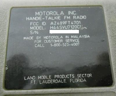
This is the serial tag off of one of my radios.
| Sample model number: H44GCU-7180AN | ||||
| H | 4 | 3 | GC | J |
|---|---|---|---|---|
| Radio Type |
Transmit Power |
Frequency Range |
Product Line |
Display |
|
H Hand- held Z Special Product |
3 Not used on low band 136-174 MHz: 2 Watts 403-470 MHz: 2 Watts |
1 30-50 MHz |
GC HT800 / MT1000 / HT600E |
J Digital Display (32 or 99 Chanels) |
|
4 30-50 MHz: 5 or 6 Watts [1] 136-174 MHz: 5 Watts 403-520 MHz: 4 Watts |
3 136- 174 MHz |
RF Radius P200 |
U No Display (Has the Rotary Channel Selector) |
|
| 4 403- 520 MHz |
R ??? Unknown ??? Seen on a 16 channel GCR high band radio [2] |
|||
| Sample model number: H44GCU-7180AN | |||||
| 7 | 1 | 9 | 0 | C | N |
|---|---|---|---|---|---|
| Squelch | Channel Spacing | Channels | Variation | Issue [4] | Packaging [5] |
| 7 PL or DPL |
0 Wideband [3] |
0 16 channels |
0 | A [6] | (blank) (bare radio) |
| 1 Narrowband [3] |
2 2 channels |
B | C Alkaline |
||
| 3 32 channels [7] |
C | N Nickel- Cadmium [8] |
|||
| 6 6 channels |
|||||
| 8 8 channels |
|||||
| 9 99 channels |
|||||
Notes:
1) Some books say 6 watts, some say 5 watts. Low band radios were only offered in one power
level - there was no low power model.
2) The single H43GCR7100CN that I have seen had factory DTMF, and that may be significant, or
maybe not. And no, it wasn't a ding or scratch on the serial plate, it was a real GCR. Or it
may have been a factory typographical error (and it wouldn't be the first one I've seen).
3) See the wideband/narrowband notes on the HT600 above.
4) Another name for "hardware version"
5) Same as the HT600
6) The A-series radios were not compatible with the enhanced MVA.
7) Notes from an email: The 32 channel MT is a very rare configuration. I've only seen a
few 7130s, and they were all low band ones, and the only one I was able to get on the
programming bench was in reality a 99-channel 30-36 MHz radio with a 32 channel model
tag (it had a 99-channel control board in it). If you find a 7130 in surplus it may actually
be a 7190 inside, or it may be a true 32 channel radio. You won't know until you try and
program the higher numbered channels. And if you do find a true 32 channel one, I'd like to
know the part number of the control board and see a photo that is clear and detailed enough
to read the part numbers on the chips.
8) The 2 watt radios were shipped with the NTN4548B "Medium capacity" battery, and the 4
watt/5 watt radios were shipped with the NTN5414B "high capacity" battery.
9) There were a small number of VHF H33GCU7100 16 channel radios made with a model tag
reading P1757A, and some UHF H34GCU7100 radios shipped with a tag reading P1759A. They
were a one-time special order and are identical to the equivalent normal radios except
for the tag.
Missing info: (contributions of information are more than welcome)
1) Photos of each of the RF boards and each of the controller boards.
2) Model chart or info, specs and photos of the P200, HT800, the MTX, MTX800, Classic and
MTX900... Anybody want to donate or loan a manual or at least scan some pages?
3) Any details on how the presence of the MDC or DTMF options affected the model number
4) Contact info for anyone who can replace the top contact set on the MT1000s / HT600Es (i.e.
the accessory connector)
Radius P200:
The UHF and high band P200 radio is basically an HT600 in a black plastic case with a
Radius escutcheon. All they did was change the labels and the dye in the plastic. Likewise
the low band P200 is a recolored and relabeled MT1000. The VHF and UHF P200 model numbers
are identical to the HT600 except that the "SVU" is replaced with "RFU". The RSS from the
VHF and UHF HT600 and from the low band MT1000 was tweaked for the P200 series. As far as
I know all they did was chnage the model numbers.
Original P200 Brochure 882 KB PDF
Accessories Common to All Genesis Radios:
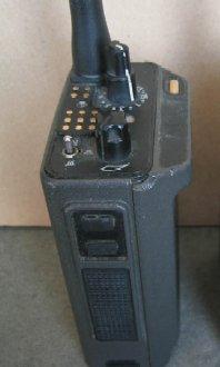
The top of the radio has the "Universal" connector (at least that's what Moto marketing called it), also called the accessory or option connector. While the drawing below is of a 6 chanel HT600 the pinout is the same across the entire Genesis product line:
| 1 | External microphone hot. | 8 | Speaker Return - See note 2 below. |
| 2 | External speaker hot - See note 2 below. | 9 | Busy (for programming and for MVA mode). |
| 3 | This is called "Option B+" in the book. It's the switched battery voltage through 560 ohms. | 10 | Remote Antenna (i.e. the center of the coax and pin 12 has the shield). |
| 4 | Push To Talk - ground this pin to transmit. | 11 | CVC Sense - See notes 1 and 3 below. |
| 5 | Ground | 12 | RF Ground (used by the MVA and the antenna adapter). |
| 6 | Serial data (bidirectional - for programming and for MVA mode). | 13 | "Sense" or "Remote RF Select" See notes 3 and 4 below. |
| 7 |
External Speaker Select - Grounded by the earphone adapter or the MVA to switch from the internal speaker to pins 2 and 8. See note 3 below. |
Note 1: CVC="Convert-A-Com", the old name (from the HT220 days) for the Mobile Vehicular Adapter (see below). When the CVC pin is grounded by the MVA the microprocessor in the radio goes into "MVA mode" and communicates with the microprocessor in the enhanced MVA (the NTN5613 series) over the bidirectional programming data pin at 9600 baud. This allows the MVA channel display, open squelch LED, etc. to stay in lock step with the radio. This fuctionality was added to the firmware in the "B" series and later radios.
Note 2: The Genesis series uses a weird custom audio output chip with three ouput pins. Despite both the block diagram and the schematic in the book indicating differently, two of the pins are the same phase and the third pin is inverted phase and all three pins are floating above ground. The internal speaker (part number 5005269T04, which depending on which book you read is either 28 ohms or 39 ohms) sits between one normal phase output and the inverted one, and the external speaker-mic uses the other normal phase and the inverted output. Again, do NOT let any audio output lead contact ground or you will be buying and installing a new U406 Audio PA module, and while I haven't checked recently, it's probably NLA (no longer available). One of my radios has a dead speaker output pin and someone along the line disconnected the speaker-mic connection and jumpered the speaker-mic output to the internal speaker. Note that this floating speaker design requires a 1:1 audio transformer between the radio and any test equipment that connects to the speaker leads (like when doing a receiver quieting measurment)....
Note 3: The internal / external switching is done electronically (no reed relays here!) and depends on a good hard ground. If you make up your own adapter make sure that the switching has no significant series resistance in pin 7 or pin 13. The CVC control pin (pin 11) is not as sensitive, but it does require a clean ground to do it's switchover.
Note 4: Motorola calls pin 13 "Sense" in the earlier MT1000 manuals, and the last version of the manual uses the term "Remote RF select". This pin is grounded by either the MVA or by the external antenna adapter to switch the radio antenna connection from the screw-in antenna mount in the top of the radio to pins 10 and 12 on the connector.
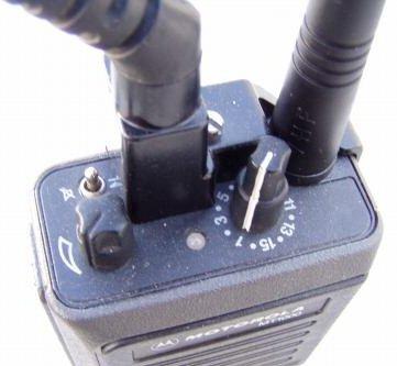
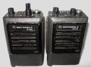
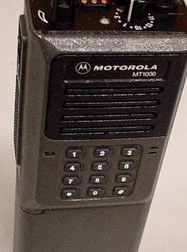
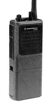
The five photos below show, in the first row, WA1MIK's HT600 (6-channel) radio with a dust cover, an 8-channel MT1000 and a 6-channel "Classic" (with a broken channel knob, more on that later). The second row has a friend's 16-channel radio (also with a broken channel knob), and my personal 99-channel UHF HT600E radio with a dust cover. Depending on the radio series, the mini-toggle switch in the top left corner has either two or three positions. Look at the top left photo below: the left position has the line through the speaker symbol signifying PL Receive mode, the the right-most position has the un-slashed speaker symbol which signifies carrier squelch mode. The conventional radios with the three-position toggle switches have the left position as PL mode, the center position as carrier mode, and the right position as scan mode (indicated with a stylized "Z" symbol). The 800 MHz trunking radio has the A-B-C assignments for the switch (and it also has a different antenna connector - an SMA. To my knowledge this was the first SMA radio that Motorola made).
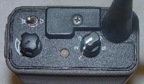
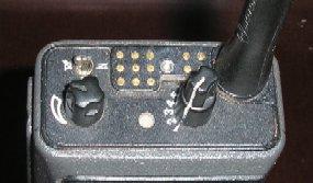
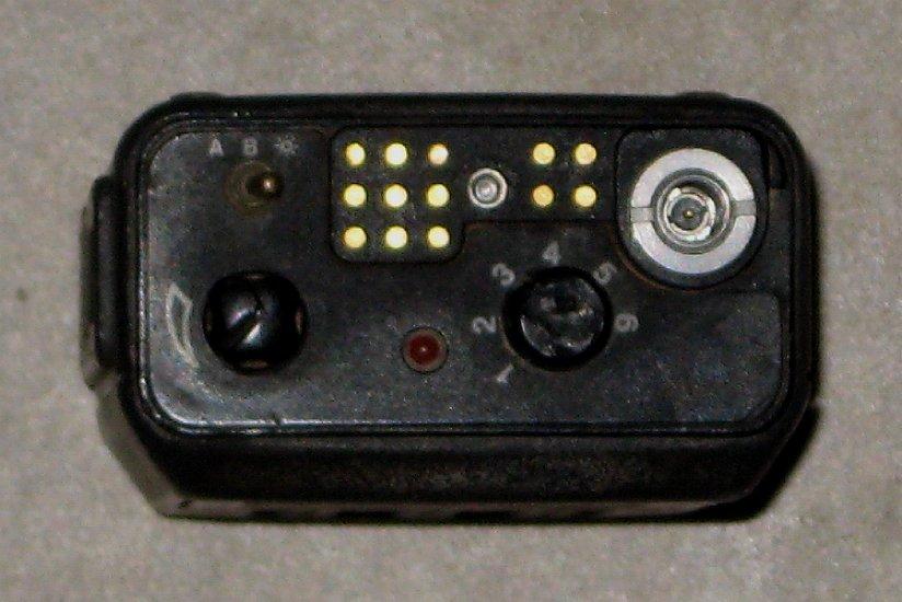
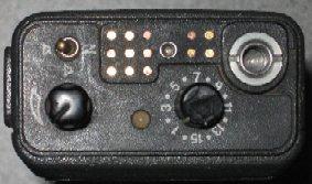
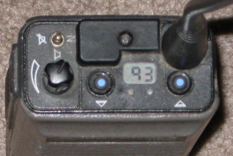
The 99 channel radios have two small LEDs, where the other radios have a single larger
two-color LED.
The 99-channel display radios have a cute trick in the firmware - if "manual display flip" is enabled in the RSS you can "flip" the display orientation so that it reads correctly when you are looking at it in your hand or on your belt. All you have to do is press and hold the two channel direction buttons simultaneously for a couple of seconds. Do the same again and it will flip back. I've never seen a 99-channel Genesis that didn't have that feature enabled.
A repair tip: Don't let a 99-channel radio get wet on the top. The seals around the up and down channel buttons crack over time and will let in water. This screws up the upper part of the radio, especially the display. The symptom is that the display will be missing segments or just shut off completely and you will not be able to see what channel you are on. Yes, the display can be replaced, but not everyone has a replacement display, a 6 inch illuminated gooseneck magnifying glass, the special tools and rock-steady hands. The seals are part number 3805558R01 and last I checked are no longer available.
The RF boards are the same between the "rotary" models and the "display" models, and the control boards are such that an 8-channel can be converted into a 16 channel, but the internals of the radios are different enough that it is impractical to attempt to upgrade any rotary model to a 99-channel display model.
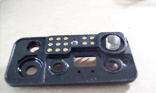
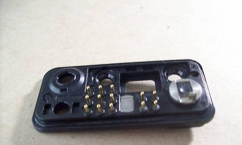
One of the options on the Genesis was the so-called "man down" button. It's
an obnoxious orange button that has a stiff spring under it to help prevent
accidental activation. When it is pressed the microprocessor keys the radio
and sends an alert signal on a specific channel (regardless of the current
position on the channel selector on the radio). As an aside, the
nameplates / escutcheons (i.e. "Motorola MT1000") for the "man
down" fronts are a different shape and hence are unique to those fronts.
You can trim a standard one down with a new fresh single edge razor
blade or a surgical scalpel and a ruler... it will look somewhat presentable,
but it's rather difficult. Best to find a proper one if you can.
Here's two photos of a MT1000 with the "man down" option... note how the
top protrudes to make the button easy to find by feel... The orange color
in the right photo is faded and way off color anyway (another indication
is that the gold pins are more yellow than gold), the "real" color is much
more like the left hand photo.
Missing info: (contributions of information are welcome!)
Part numbers for the "man down" faceplates.
A better photo of a man-down button faceplate.
A digital photo of the component side of a man down faceplate.
Accessories:
Unfortunately you can only use one accessory at a time... The available toys include:
| IMPORTANT | ||||
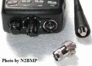
Look at these photos: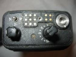 The Genesis antenna bushing has a has a solid antenna ring, hot to RF, on top. |
 Other radios, like this GP68, have a hot recessed center and a grounded outer ring. |
 Yes, the antennas made for them will work |
||
People think that just because antennas from other radios happen to fit a Genesis radio (Motorola has used the 1/4 inch diameter by 32 threads per inch antenna fitting for years) that the antenna adapters will as well. WRONG !!! Note how the MT1000 (in the left photo) has the antenna ring fully hot. Many other radios, including the GP68 in the center and right-hand photos have a grounded ring around the hot antenna center bushing. The antenna adapters for those antennas depend on that grounded ring. The Genesis antenna adapter gets its ground (and depends on it) from the accessory connector. If you put one of those other antena adapters on a Genesis then plug in a coaxial antenna cable into the adapter you will find that both sides (i.e. the center conductor and the shield) will be hot to RF (radiating). This mismatch will generate high SWR which will eventually damage the Genesis radios transmitter. |
||||
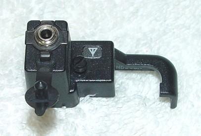
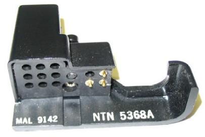
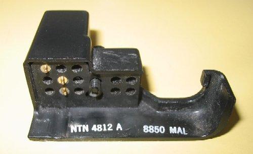
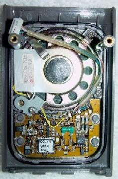
This photo (courtesy of Dennis Hicks KG6OMR) shows the bottom of the audio
adapter - note that the three pins are on the left side where on the RF adapter
the three pins are on the right.
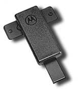
Speaker-Microphones:
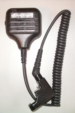 An NMN6145B Speaker-Mic |
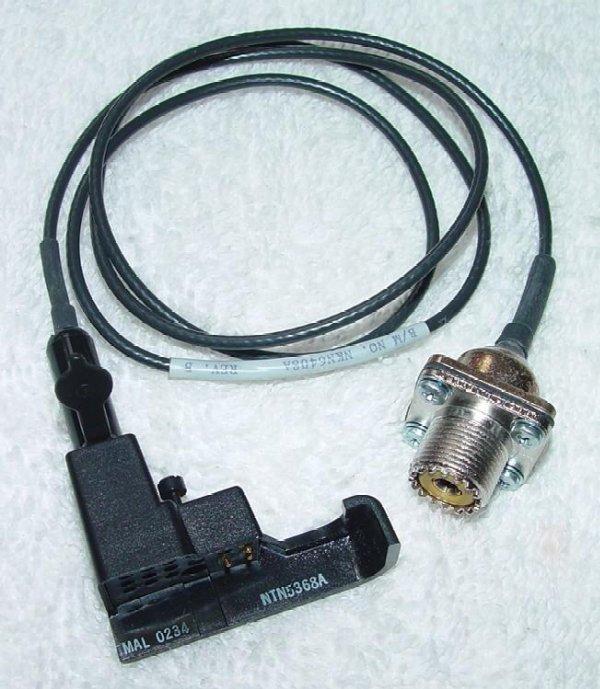
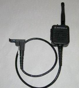 An NTN5050A Public Safety Speaker-Mic. New price on this unit was about $115 (less the screw-in antenna) Does anyone know who makes the bulk cable for these units? |
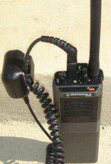
All of the public safety speaker/microphones use a thicker straight cord rather than a curly cord due to the fact that there is an antenna coax inside the cable jacket. That coax feeds the antenna connector that is mounted into the top of the speaker-microphone.
Two points about the straight-cord public safety speaker mics (also called PS speaker mics):
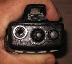
 Here's a photo of the NTN6155 series on a radio. As you can see there is no earphone jack. This photo also shows you why the frequency knob is so tall - when you add any accessory, especially a speaker-mic, you can't reach a standard height knob. Even with the very tall frequency knob it's still crowded. This is one reason that the connector was moved to the side on the follow-up radio series - the Jedi (HT1000, MT2000, etc). |
 Some folks trim the height of the channel knob, either with a hacksaw, or a pair of diagonal cutters and a file to clean up the sharp edge... or sometimes they get bumped and just break off. I've used the radio on the right, and the knob is just tall enough that you can easily rotate it, however it's short enough that you can't rotate it by accident. In other words, the knob is short enough above the radio that it's the one you give the newbie at a public service event where you don't want him changing channels by an accidental bump. |
BTW, I've seen a tiny 4x4 DTMF pad mounted to the back of an oversize speaker-mic originally intended for another radio and rewired to a Genesis speaker-mic cable.
Here's a service hint on Genesis speaker-mics: Look at any of the schematic links below. There is a 9v zener diode across the microphone cartridge, labeled VR1. If it's shorted you will have almost no transmit audio. If it's open the audio can be loud and "fuzzy", or if the overvoltage blows the mic element (sometimes it does, sometimes it doesn't) there can be no audio. So if you have a speaker-mic that has bad audio or no audio, first test the zener before you replace the cartridge. You don't want to damage the new cartridge due to an open zener.
Another service bench hint: Take an old public safety speaker / microphone and take the speaker-microphone head off of the cord. Add a female crimp-on RF connector to the coax stub, and a DB-connector to the other wires. You can solder a mini-toggle switch across the PTT and Ground leads, and on other pins you can inject audio into the microphone circuit for transmitter testing, or sense audio for SINAD / quieting testing, etc., i.e. a poor-man's RTX test set. Just remember to put a 1:1 audio isolation transformer on the radio audio output so that neither speaker lead ever gets grounded. The "real" RTX also has a 1:1 audio isolation transformer and a 10:1 resistive divider from the audio input (i.e. where an outside audio oscillator outputs 450mv and the level to the radio is 45mv). Due to the poor construction of the adapter you will need to use a screen room, or to at least take the plug on the radio end of the cable apart and glue copper foil inside the plastic shell, and ground it.
Part Numbers:
The non-public safety microphone cord is part number is 0105959R75
and it will set you back about $90 plus shipping (2006 price).
Missing info: (contributions of information are welcome!)
1) Anybody have the part number for the replacement cord for the public safety speaker/microphones?
2) Anybody have a photo of the the matching NTN5560C HiRose adapter ?
3) Anybody have the part number of the HiRose connector speakermic ?
4) Anybody have a photo of any of the surveilance / undercover / covert kits ?
PL and DPL:
The HT600 radio has a 6 position switch, and hence can have a maximum of
6 RF channels but is only capable of four coding schemes that are shared among
all channels. You can NOT have six completely different combinations. I don't
know if the limitation is in the radio or the RSS, but it doesn't tell you
during programming; things just don't work like you'd expect. According to
the RSS manual, the available combinations are:
(1) one tone PL, one DPL, one quickcall
(2) two tone PLs, one DPL
(3) three tone PLs, one DPL
(4) one tone PL, three DPLs.
It would have been nice to have another option of four tone PLs, but Moto
engineering decided nobody would ever need that. If someone wants to do some
investigating where the limitation(s) is/are and let us know, I'll update
this paragraph. If the limitation is in the RSS and someone develops a RSS
patch that works please do a how-to article (see the GTX section for an
example patching procedure article).
The MT1000 / HT600E radios come stock with all standard PL and DPLs in them, and
the radio can do split and mixed tones/codes/carrier on a per channel basis...
HOWEVER there are only thirty "slots" for the tone / DPL
code information in a 99 channel radio, and you really should program the
slots BEFORE you program the RF frequency information. The simplest way is
to make up a spreadsheet of the receive frequency, receive tone, transmit
frequency, transmit tone, etc. and then count how many tone / DPL
combinations you need, and pray that it's thirty or less. Prefix the DPL codes
with "D" as you make up the spreadsheet. Then sort the spreadsheet by
tone / DPL code. Then program the PL / DPL page in the
RSS (and since you used a "D" the DPLs will be segregated and moved to the
end). This way the the tones are first, in order of increasing tone frequency,
then any DPLs and in numeric order. Once the tone / DPL code page is
programmed only then do you program the RF frequency information.
I learned this 30-slot limit and the increasing toen / DPL sequence
the hard way, as I skipped 77.0 Hz as I programmed the tone / DPL
table on my 99-channel UHF radio and was one short. I ended up moving a
repeater system and all the users to a tone that was already in the radio.
Later on I bought a VHF radio that was already programmed for most of the
2m repeaters in my area but the entries in the tone table were cronological,
not by frequency. It's a real pain to add new channels as nothing is in numeric
order.
Note that there is no Multiple PL ("MPL") feature like on later radios, if you want the option of changing tones on the same RF frequency you will have to program multiple channel slots with duplicate RF information and different tones/DPLs (this is one reason the 99 channel radios are so popular).
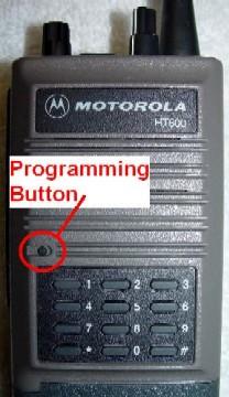
DTMF:
The DTMF is fully contained in the front cover of a Genesis radio. Adding DTMF to a non-DTMF radio consists of swapping the cover and reprogramming the radio so that the main microprocessor "knows" that it's there. Swapping a front cover on a Genesis radio is a 15-20 minute job the first time you do it and less than half that the next time. There were at least four DTMF front covers made for the Genesis line. All of the DTMF fronts I've seen are 12-button, as far as I know there never was a 16-button DTMF option in ANY stock Moto radio until the GP68 series was introduced. If you need 16 button DTMF I suggest you contact Joe Oliveras at PIPO and mount one of his small pads on a plain front cover - it's only a 3-wire hookup... (power, ground and DTMF audio out).
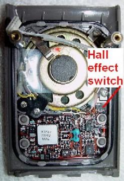
Here are photos of two of the known fronts, the left hand photo is of an NTN4627B front, the center photo shown an NTN5596A, and the right photo is a plain front radio. There were also the NTN5040A and the NTN5395A fronts. The tiny button to the top left of the "1" key in the photos is used to program DTMF strings in to the DTMF chip memory... The programming clip uses a magnet to trigger the Hall Effect sensor in the faceplate. Programming details are in the user's guide. One note: DTMF and the orange "man down" panic button on the same front panel was an available combination but is almost impossible to find. If you ever pick up a radio that has that combination, be assured that finding a replacement front will be next to impossible.
 This NTN4627B front came with an HT600 escutcheon. The NTN5215 looks the same. Photo by WA1MIK. |
 The NTN5596A has a different physical layout. The NTN7910A looks the same. |
 A "plain front" radio for comparison. The NTN4955 (A or B) is for the HT600. |
 Photo by WA1MIK.
 A rear view of the NTN4627B. |
 A rear view of the NTN5215A. |
 A rear view of the NTN5596A. |
 |
|
MDC1200 was an option and it was totally contained in yet another different front cover. As such the radio unfortunately offered only one MDC ID for all channels. The later handheld products (the Jedi series) was the first hand held radio to offer multiple MDC unit IDs. The optional Genesis front panel types that support MDC unit ID are: (thanks to K2HZ for this list and the DTMF list below)
There are also DTMF only keypad versions without MDC1200.
The 800 MHz and 900 MHz radios also had DTMF covers available, but I have no information on the NTN7910A cover on the one 800 MHz radio I looked inside.
The NTN5596A "continuous" DTMF is needed for most amateur radio DTMF applications. It allows all DTMF digits plus # and * to be sent for the duration of the key press. The NTN5040A "timed" DTMF and the NTN5395A "ANI" DTMF are useful only for some specialized applications that work with 150ms long DTMF burst tones (and they can be preprogrammed). A resistor value could be changed to lengthen the 150ms burst to as much as 750ms, but that fact was not documented in the manual (i.e. each shop had to reinvent the wheel).
Missing info: (contributions of information are welcome!)
1) Supposedly there was a field mod to convert the 5040 (timed) into a 5596
(continuous) and vice versa. If anyone has the that information we'd
like to have it to include here.
2) For that matter, if anyone has any manual sections or any photos of any
of the above MDC or DTMF faceplates we'd like to have them.
3) Any info on the 800 MHz and 900 MHz DTMF covers.
4) The catalog lists the NTN5554A as the current DTMF retrofit kit for the
P200, anybody have any information (or a photo) ?
Useful Repair / Cosmetic Part Numbers:
If anyone has photos we'd appreciate them.
Additional numbers are on the Parts and Accessories List for the appropriate radio; see the download / link section below.
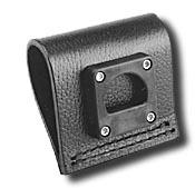
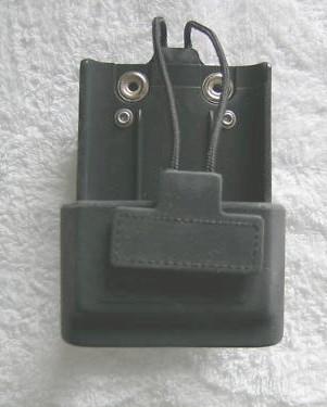
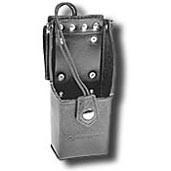
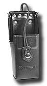
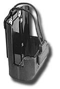
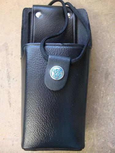
Belt Clips and Protective Cases:
A belt clip could be mounted to the back of the radio, but most people
used a protective leather or ballistic nylon case.
We have photos of some of the clips and cases - they are shown below as links. If anyone
has photos of any of the others (or could take a photo of them) we'd appreciate it.
The "Carry cases" included:
Antennas:
The antenna adapter is listed in the Accessories section above. See the caution note in that section regarding using an antenna adapter made for another radio.
The flexible antennas made for the public-safety speaker-microphone (with the straight cord and the antenna on top) are listed in that section above.
Antennas for the Genesis also fit other radios including the Motorola HT1550, HT1250, HT750, P1225, SP10, SP21, SP50, P10, P50, P100, P200, GP68, GP140, GP300, GP320, GP350, GP380, GP640, GP680, Spirit M, CP200, Pro1150, Pro3150, Pro5150, Pro7150, Pro9150. SP2550, and SL70.
The flexible ("Heliflex") antennas listed in the Moto catalog for the HT600 are:
Missing info: (contributions of information are welcome!)
The physical length or other distinguishing characteristics of the NAD6282A
(136-150.8 MHz), NAD6283A (150.8-162 MHz), NAD6284A (162-174 MHz), NAE6231A
(403-438 MHz), NAE6232A (438-470 MHz), NAE6233A (470-512 MHz) antennas so
that they can be identified when you find them in the junk box, or in a bin
at a swap meet.
Batteries:
Nickel-Cadmium (NiCd) batteries deliver 1.2v per cell, Nickel Metal Hydride (NiMH) deliver 1.25v per cell. Each Genesis battery pack uses 8 cells to produce 9.6v from the NiCds and 10V from the NiMHs. The alkaline cells produce 1.5v each so 7 cells yield 10.5v. The battery pack total voltage will be a little higher when freshly charged. There is a reasonably in-depth article on NiCd batteries at Wikipedia which is worth a read.
The Genesis series never had a Motorola-provided penlite cell pack (i.e. one that holds AA sized alkaline cells, also called a "clamshell"). I've been told that a couple of aftermarket accessory companies made them and since this page went up I've had several emailed inquiries asking if anybody is still making an HT600 / MT1000 penlight pack. If anybody knows of a source of them, even one or two, please contact the author.
NiCd, NiMH and alkaline packs are available from several aftermarket battery suppliers, including Interstate Batteries (yes, the folks that make car batteries), and Radio Shack (believe it or not)... Look here for Interstate and search for MT1000, or here for RadioShack and click "Batteries & Power, Find A Battery, Two-way Radio, Motorola, MT1000.
The batteries are electrically identical between the HT600, MT1000 and P200, the difference is the dye in the plastic. HT600 batteries are tan, MT1000 batteries are gray and the P200 batteries are black.
All Genesis packs (NiCd, NiMH and alkaline) are sealed and once dead are intended to be disposed of (i.e. they aren't intended to have the cells replaced like they re in an Icom BP-series battery).
From an email to repeater-builder:
Here's an interesting way to open a HT600 / MT1000 battery pack: Put it
into a ziplock bag and suck the air out (i.e. no or very little moisture to
condense on it), freeze it solid then break the glue with impact shock. I put
mine in the freezer on top of the ice cube trays for several days, then take
it out and SLAM it (bottom side down) onto the wooden chopping block. If the
bottom does not pop out I SLAM it a second time, then check again. If necessary
I put it back into the freezer for another couple of days and try again then.
Some stubborn batteries have taken as many as 8 slams. I've not had access to
dry ice or a CO2 fire extinguisher to try an even colder temperature.
Apparently the glue Moto used is cold-sensitive (some of the newer and aftermarket
batteries are sonically or solvent welded and this trick doesn't work). Once the
bottom pops off I can slide the cell pack out and replace the cells. If you do the
WA1MIK charging-rate mod to your charger you can use NIMH cells and reuse the
existing NiCad-rate thermistor.
Note that you should always use cells that are from the same manufacturer, size
(i.e. MaH), preferrably the same manufacturing batch (i.e. date code), and trickle
charge them individually at a C / 30 rate for a couple of days before you
assemble them into the battery pack. You do NOT want to mix different sizes, or
charged and discharged cells into a series string.
From another email to repeater-builder, after reading the above one:
Just set the bottom of the battery on top of a brick of dry ice for 20 to 30
minutes, then slam it down on a piece of wood. Or use canned freeze mist, or
even the canned air they sell for blowing out computers (turn the can upside
down and the cold liquid comes out). Spray the liquid air on the seam, go round
and round about 5-6 times until it is not going to get any colder, and SLAM it
(bottom side down) onto the wooden chopping block. The cover will pop off with
the first slam (but as you said in your posting this trick won't work on the
sonically welded or solvent welded cases).
Read the note in the charger section before you charge any Nickel Metal Hydride battery pack. Apparently a number of the aftermarket battery manufacturers are using the same thermistor for both the NiCd and NiMH batteries - and the teperature profile of the NiCd thermistor can kill a NiMH battery since it gets hot enough to damage itself, but not hot enough to trigger the switchover from charge to trickle. Changing one resistor in the charger fixes that. And you can use a toggle switch to select resistors (i..e select between NiCd and NiMH).
The battery table has been moved to its own article. Click here or on the link at the bottom of this page.
Battery Chargers:
Only the NiCd and NiMH are rechargeable - never try and charge an alkaline pack.
The chargers available from Motorola for the genesis line are NiCD only as NiMH
hadn't come out yet. There are aftermarket NiMH chargers, but the most common Genesis
chargers are the older Motorola 1-hour chargers.
If you have ANY of the stock Motorola rapid chargers DO NOT
charge a Nickel Metal Hydride pack until you have read this
article and modified your charger.
Apparently a number of the aftermarket battery manufacturers are (were?) using the
same thermistor for both the NiCd and NiMH batteries - and the MiMH cells didn't
get hot enough to cause the switchover from charge to trickle. The charger stayed in
the charge mode and the excess current caused the NiMH cells to cook themselves to
death. Changing one resistor in the charger fixes that. And you can use one toggle
switch to select resistors.
If you drop an NiMH battery that has the wrong thermistor into any unmodified
charger for even just one charge cycle you can overheat it to the point of
permanently ruining it.
If you drop a battery into one of the single-pocket (i.e. desktop) rapid chargers and both charger LEDs flash on and off that indicates one of three things - one, you have a an open battery pack (which could be caused by an open thermal breaker inside), or two, you have shorted cell (or cells) in the battery pack (i.e. the pack is delivering a too-low voltage) or three, the charger has a problem - which could be as simple as a bent pin in the battery cup. A voltmeter across the top of the battery will provide the answer for the first two possibilities (no voltage or low voltage)... As far as low voltage, I've left a radio on accidentally for several days and it will discharge a battery to below what the charger thinks is OK. I've brought an over-discharged battery up to normal voltage (so that the charger will charge it) by simply taking a fully charged battery and jumpering the top contacts of the charged and the low battery together (with a few hundred ohm current limiting resistor in the positive lead) for a few hours - positive to positive and negative to negative. This brings the low battery up to enough voltage to satisfy the charger. Then drop the low battery into the charger. You could also use a wall transformer that has a DC output higher than 12v. Just limit the current to under less than 1/10 of the milliamp-hour rating (i.e. under 100 ma for a 1AH battery). Since the lowest capacity battery was the 550 MAH intrinsincally safe battery if you limit the charging current to 50 milliamps then it will work with every battery that is out there. A list of all the batteries made for the Genesis line that I know of is here.
The design of the common single cup rapid desktop charger has the power transformer, rectifier and filter caps powered continuously. The on / off switching is done at a low voltage DC point in the circuit. More than one person has added a mains power switch into the back of the housing. A two-pole three-position, center-off switch has been used to provide the power on / off and NiCd / NiMH switching (one pole with both sides jumpered together for AC power, the other for the resistor selection).
The multiple (or "gang") charger for the Genesis series has 6 pockets and is a totally different design that supports both ni-cad and ni-mh batteries. The model number is NTN4668A (117 vAC) and NTN4922A (220 VAC). More information is available on the charger page.
The rest of the battery charger information has been moved to its own article. Click here or on the link at the bottom of this page.
Mobile Adapters and RF Amplifiers:
The earliest mobile charger was made for the HT200 series and it was basically a box bolted under the dashboard. All it contained was a mobile nicad charger that took the vehicle power (+12v to +15v DC) in and delivered +18 to +20vDC out at 60ma. A later redesign (during the HT220 era) supported the "Convert-a-com" radio - a regular HT220 except with a special front that had a number of contacts on the lower edge of the speaker grille area. These contacts were connected internally to the speaker, microphone, PTT, etc circuits in the radio and allowed the connection of a mobile microphone jack and an amplified speaker. A permanent magnet in the sleeve "reached" through the aluminum frame and magnetically switched the radio to an external antenna connector. This underdash charger unit was called the "Convert-A-Com mobile charger" (but some folks called it a "jerk-and-run") and was used with the HT220 and MT500 series radios. When the PAC-PL and PAC-RT mobile repeaters (sometimes called a mobile extender) came along they added a switch on the front panel (labeled "Mobile Repeater On/Off") and a second one in the bottom of the radio pocket. When the front panel switch was on, and the radio was out of the pocket the crossband repeater was enabled.
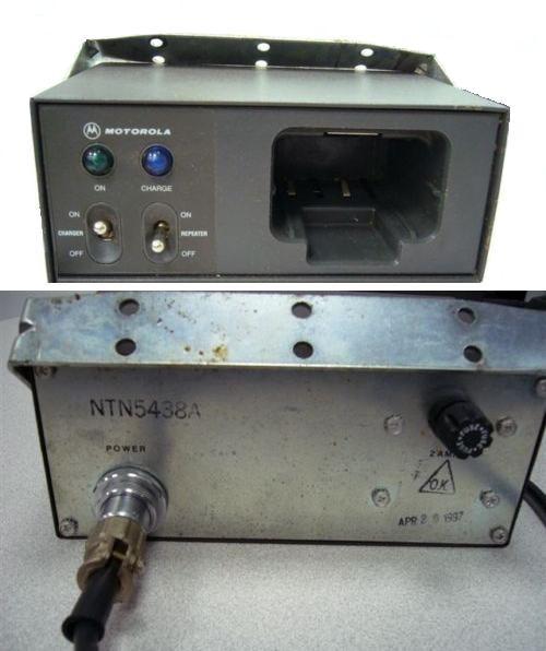
Both the regular HT220 mobile charger and the HT220 Convert-A-Com were still in the product line when the first of the Genesis series radios (the HT600) were being developed and was updated with a new, properly sized pocket for the different dimensions of the new handheld (see this photo). I have seen one that had a clear lens on the left hand lamp (labeled "On/Charge") that lit up either green (on) or amber (charging), and a red lens on the right hand lamp (labeled "Repeater On"). I have no idea if that was a later model, a prototype that escaped from the lab, or a one-off very-well-done custom modification.
As part of the Genesis development the entire mobile charger unit was redesigned to clamp the radio into the charger pocket (the US Forest Service, the California Department of Fish and Game, the US Border Patrol, and the military had complained - loudly - that the radios bounced out of the chargers on rough roads), to add both a channel display and a mobile microphone and speaker, and was given a new name: the Mobile Vehicular Adapter (MVA), and it was redesigned even later for the Saber series of handhelds and was renamed yet again as the Saber Vehicular Adapter, or SVA). Despite the new name(s) some folks still called them a "Jerk-And-Run".
The Genesis Line MVAs come in two versions, the basic, and the enhanced. The enhanced has the rapid charger and the channel display.
The information on the MVA and its associated RF amplifiers and amplified mobile speakers has been moved to this article - An Overview of the Genesis Mobile Vehicular Adapter (MVA). This article also includes the information on modifying the MVA charger section for NiMH batteries.
The basic MVA has a single (slow) rate battery charger in it, and one of the features on the enhanced MVA was rapid, standard and trickle rate charging. The circuit board was the same, a basic MVA could have the charger field upgraded by adding the missing parts, and in fact I've seen one that had the solder sucked out and the parts poured in. The enhanced MVA has the same overcharging problem with NiMH battery packs that the desktop and gang chargers have (it's the same schematic except with different R and C numbers), and the fix is the same: change one resistor. This is documented in the MVA article mentioned above and in the link list below.
Missing info: (contributions of information are welcome!)
Does anybody have any of the following that they would be willing to contribute?)
Any missing model numbers for mobile, single unit desktop or gang (6-pack) chargers.
PDFs of the mobile charger manuals, or at least the schematics.
Digital photos a desk or mobile charger interior (a "photo tour").
Digital photo of an older style mobile charger with and without a radio in it.
Frequency Bands, Ranges and Splits:
As said above, No matter WHAT the model tag says, no HT600, HT600E, HT800 or MT1000 will ever do the entire 30-50 MHz, 136-174 MHz, or 406-470 MHz frequency band listed on its model tag / label. Are you listening, eBay sellers? Each radio will do only a portion of that model tag frequency spread, called a "range", "split", or a "bandsplit". This is a simple law of physics - the RF engineering technology of the day handn't advanced to the point where the wider splits were practical (like on the later product lines).
As shown above in the model tables, the frequency band is indicated by the second digit of the model number. Unfortunately, there are only two ways to determine the bandsplit of your Genesis. You either have to read the radio with RSS and look at it, or you have to open the radio up and read the model number from the RF board (it is printed close to the lower controller connector) and look that number up in the table below (which is copied right from the book).
|
||||||||||||||||||||||||||||||||||||||||||
|
|
|||||||||||||||||||||||||||||||||||||||||
Some of the HT600 RF boards were used in the MT1000 / HT600E / P200 radios, others were brand new with the later series of radios. Note that the HT600 used three splits for high band, and the MT1000 does it in two. The RF boards are interchangeable, and while Moto says that they never made 99 channel MT1000s with the NUD6772 or NUD6782 board I've seen them - and they were not radios that were frankensteins (built from spare parts).
If anyone has a part number that isn't in the tables please drop me an email with the information (and a photo if possible).
|
|||||||||||||||||||||||||||||||||||||||||||||||||||||||||
|
|
|
|||||||||||||||||||||||||||||||||||||||||||||||||||||||
|
The low band radios are either 5 or 6 watts depending on which book you read. The 470-500 and 488-520 MHz ranges are not available in 2 watts |
|||||||||||||||||||||||||||||||||||||||||||||||||||||||||
Programming:
A simple and very feasable way to make a programming cable is to take an old speaker-mic cable and move some of the pins on the radio end around so they make contact to pins 5, 6, and 9 on the accessory connector, then put a DB25F where the speaker-mic body used to be. Another way is to take a earphone or external antenna adapter, remove the 1/8 inch phone jack, and use the resulting hole for a cable exit hole, move the three pins to 5, 6 and 9, then put a DB25F on the other end of the cable. The cable from a dead computer mouse will work quite nicely for that.
Alternatively, if you want to make one from scratch, here are some useful part numbers for the accessory connector:
Programming Cable pinout:
| Signal Name |
Radio Pin |
DB25F Pin |
|---|---|---|
| Ground | 5 | 1 |
| Data | 6 | 24 |
| Busy | 9 | 8 |
| Jumper | (none) | 4-11 |
Cloning Cable pinout:
| Signal Name |
Radio 1 Pin |
Radio 2 Pin |
|---|---|---|
| Ground | 5 | 5 |
| Data | 6 | 6 |
| Busy | 9 | 9 |
Pin Numbering of Radio Connector (bottom view)
| 1 | 4 | 7 |
| 2 | 5 | 8 |
| 3 | 6 | 9 |
| (+) | (o) | |
| 13 | 11 | |
| 10 | 12 |
The Genesis line is old enough that the earlier RSS has the computer speed problems that are covered in detail on the RSS pages at this web site.
The Radio Service Software (RSS) for the HT600 is part number RVN4005 and is DOS only, it does NOT run under Windows. The last released version is R02.03.01 dated 01-Oct-93 is and is known to run just fine on a Pentium 100. I've not had the opportunity (or necessity) to try The HT600 RSS with anything faster than a Pentium 100. I don't know how fast you can go with it. The "HT600 Programmer / Tuner User's Manual" (the book that comes with the RSS) is 6881045C55 at about $35 (that is a manual price, not the RSS price).
The Radio Service Software (RSS) for the MT1000 (and therefore the HT600E) is part number RVN4017 (5 1/4 inch floppies) or RVN4018J (3 1/2 inch floppies). The current (last) version is R03.03.00 dated 12-Feb-01 and is known to run fine on an 800 MHz Pentium 3. I have not needed to try anthing faster - and don't really want to use one of my radios as the sacrifcial lamb. Unless you are able to locate that revision you will need to locate a 286 or a 386-25 to 33 MHz PC. ANY 486 will be too fast when running the 1-Jun-94 version or anything earlier.
As said above, the high band and UHF P200s are HT600s inside and the low-band P200 was a relabeled MT1000. I have not had a chance to play with any P200s. I do not know if the HT600 software will talk to the high band and UHF P200s, or if the MT1000 software will talk to the low band radio. The Moto catalog shows a dedicated P200LB package for that radio.
The outer plastic cases from the HT600, MT1000 and P200 are almost identical and a lot of frankenstein radios have been built from spare parts. I have seen a 99 channel UHF radio in a HT600 case and the label was from the 2 channel HT600 that was originally in that case. I've also seen a P200 UHF radio in a low band MT1000 case. Unless you know the history of a particular radio sometimes you need to try all the different Genesis line RSS to find the one that works for your particular radio.
As mentioned above, the 32 channel radios MIGHT be 99 inside. You won't know until you try it.
The Genesis radios can do any standard PL tone or DPL code and both transmit and receive RF and tone frequencies / codes are independently programmable on a per channel basis. In the 99 channel radios you have a maximum of 30 tones and codes. It's not obvious from the RSS manual, but you will be a lot happier if you program the tone / code table BEFORE you program the RF frequencies.
The thirty tone / code limit can be a real annoyance on a 99
channel radio... (been there... needed 31, had to change the tone frequency
on an already-in-service commercial UHF repeater to a tone that was already
in the radio to solve the problem... then reprogram a 20 radio fleet to match
the changed repeater). I really suggest that you plan out on paper (or an
Excel spreadsheet) all your RF frequencies, tone frequencies and DCS codes,
then sort by the tone/DCS column and make sure that the count does not
exceed thirty.
And if you want to make your programming life easier you need to program the
tone / code table first with the tones in increasing frequency
sequence followed by the DPL codes in numerically increasing sequence. Then
when you start to program the RF frequencies you can step through the PL tones
and DPL codes and as you press the keyboard up and down arrows they will
go up and down in tone frequency / DPL code.
If you are going to program a 99 channel radio full of frequencies you
will want to do a quick test first - just program a half-dozen frequencies
with a few sample frequencies at the extremes of the range you intend to
use. For example, maybe 144.33 simplex, a few in 145 and 147 MHz, maybe
the 151.625 MHz itinerant channel, maybe one in 155 MHz and another
in 158 MHz, maybe a weather channel at 162 MHz, plus a frequency
in the 174 MHz range.
On a 438-470 MHz UHF radio you should pick a 439 MHz frequency, a
few in 440-450 MHz, maybe 462.9125 MHz and 467.9125 MHz, and
maybe 462.55 MHz and 469.975 MHz.
The purpose of this test programming is to make sure that both the receive
and transmit VCOs maintain lock across the entire frequency range you intend
to use (a continuous beep when the PTT is held down is the indication of an
unlocked VCO). If the radio behaves properly then fill out the frequency list,
however do NOT program channel 88! Skip over it (or if you have to use it make
the last one you use).
The reason? a display of 88 is used to indicate an error condition, most
commonly it means that the VCO is not locking (probably due to an
out-of-VCO-tuning-range frequency being programed).
Naturally, if 88 is not programmed, and all of a sudden the radio is displaying 88 then the radio has a problem.
Missing info:
(a) MT1000 and P200 RSS Manual numbers
(b) P200 RSS package part numbers, revision information (including dates)
(c) A step-by-step article (with screen shots) on programming an HT600 or MT1000.
Programming the Scanlist:
The 8, 16, 32 or 99 channel MT1000 can scan up to 8 channels, and a default scanlist can be programmed into the radio using the RSS. Yes, the 99-channel radio can only scan 8 channels, and if anyone knows how to get around that limitation please let me know and I will add it to this page. As far as I can tell the 8 channel limitation is a leftover from the firmware rewrite when they went from 16 to 99 channels. It was coded in the 16 channel model as 50% of the channel count and when they increased to 99 they didn't change that part of the code. Maybe there wasn't enough RAM, or enough time for a rewrite of that section, no telling.
I've often thought that if an electronic copy of the firmware was available someone could reverse engineer it back to source and find out why.
To program the scanlist: (note: in the MT1000 RSS the parameter "USER SCAN PROGRAM" must be set to "ENABLED").
There are two option buttons on the side above the PTT bar (clearly visible in the "man down"
photo above). The upper one is usually configured to blow squelch.
1. Turn on the radio
2. Press lower button and turn switch at a top of radio in to scan mode
(continous BEEP tone)
3. Release lower button (BEEP tone will stop),
4. Select the channel you want to add to scan list
5. Press a PTT button (single short BEEP)
6. Set another channel to add to scan list with channel knob
7. Press a PTT button (single short BEEP)
Repeat steps 6 and 7 for a total of 8 channels. If you don't have 8, then repeat
a couple to make 8.
8. When you get to your last one, the radio will start to BEEP BEEP BEEP at you. Get out
of this mode by flicking the switch to the center position (single long BEEP) and voila;
you have a brand new scan list. Next time when you turn the switch at the top of radio to
the SCAN position the radio will scan the new set of channels.
Keep in mind that each time you enter the scan programming mode, your previous scan list is erased - you can't overwrite an old channel, you have to enter a whole new list of 8 channels...
Cloning:
The MT1000 radios and probably the rest of the Genesis line are smart enough that one can program the other - i.e. if you have several identical radios you can program one using the RSS and a RIB and then clone to the others with the NKN6376A cloning cable. You have to enable cloning with RSS before that will work (in both radios, I think). Unfortunately the factory cloning cables are rare - too many were converted into pairs of programming cables by cutting them in the middle and adding DB-25 connectors. I'm repeating myself on purpose here: the two radios have to be absolutely identical to be cloned. There are some rather confusing instructions on the BatLabs site in the Model-specific / MT1000 area. If anyone has had good results cloning these radios, please send a detailed procedure to the maintainer of this page.
Disassembly and Repair:
The Genesis line package comes apart in a non-obvious way. Bob WA1MIK scanned and PDF'd the disassembly section of his HT600 manual, and the HT600E Service Manual 6881050C45-O covers the differences in the 99-channel radios.
Missing info:
1) A photo sequence of how to disassemble and reassemble a radio.
2) What is involved in swapping an RF board, or a control board.
Miscellaneous info:
The official Moto tuning tool for all the Genesis RF boards is the part number 6605106N01. It fits all the tunable coils, the receiver preselector, adjusts the synthesizer reference oscillator frequency, and all of the various trimmer capacitors. In late 2006 it listed at about $12. The small metal tip is much more fragile than it looks. Be gentle with it.
The 0180358A59 Programming Aid enables programming of the DTMF pad from outside of DTMF optioned radios. It is a very rarely needed device, and is mentioned here only in case you stumble across one. (i.e. once Google indexes this page and catches the 0180358A59 number someone searching for it will find this paragraph).
Comments on using a Genesis series radio on amateur radio frequencies:
The Genesis portables were made in bandsplits that cover 2m and UHF. The 30-36 MHz low band radios can be "stretched" to 10 meters (28-30 MHz), and the 42-50 MHz ones can be stretched to 6 meters (50-54 MHz, see the article below), but as said above, the antenna limits the RF coverage of any low band radio to about 1 MHz of spectrum (and a low band rubber duck is a better blackjack that it is an antenna). When you buy a radio on eBay there is no way to tell which bandsplit the seller is offering without either (a) reading it with the appropriate software and programming hardware; or (b) physically opening the radio and checking the part numbers of the RF-sensitive modules. If the seller volunteers the split information you are counting on him being knowledgeable on the individual radio he is selling.
Programming a Genesis will require appropriate RSS (get the last version), programming cable (which you can make from a audio adapter, antenna adapter or an old speaker-mic cable), a RIB and an older computer that can run the software under MSDOS or PCDOS ver. 5.x or 6.x.
The official story is that if you are moving the receiver more than +/- 4 MHz away from the original operating frequencies it will require the front end retuning for best performance (in other words, the highest and lowest RX frequencies are within 8 MHz of each other). However I have found that the high band radio will work reasonably well on amateur (146 MHz receive), Civil Air Patrol (148.5 MHz) and MURS (154 MHz). The UHF radio is wide enough that you can stagger-tune it and get reasonable performance on both amateur (446 MHz receive) and on GMRS (462 MHz receive). The transmitter will work over the entire 430 - 470 range just by changing the programming. The UHF alignment instructions are in the HT600E document available above.
Some of the 2 channel radios are locked at two, some can be bumped to 6. The 6 channel radios are fixed at 6, the 8 channel radios can be bumped to 16, the 16 channel radios are stuck there, the 32 channel ones can usually be pushed to 99 (see above). The 99 channel radios are relatively rare. The 8, 16 and 99 channel units can be programmed to do scanning of up to 8 channels. The radios can do any standard PL tone or DPL code and both transmit and receive RF and tone frequencies/codes are independently programmable on a per channel basis - but as mentioned above you have a maximum of 30 tones and codes.
The radios are wonderful units, and will survive a bulldozer driving over
one (ask me how I know...), but I do not recommend getting a Genesis for
everyday amateur radio work unless the radio comes with a good battery and
a charger and you:
A) Have a limited number of RF channels you use (and if a 99 channel radio,
thirty or fewer combinations of tones/DPLs).
B) Do not need front panel programming of RF frequency and tone.
C) Do not need 16-button DTMF (i.e. you are not a repeater control op).
Finding a DTMF front for a non-DTMF radio may be difficult, and then
it's only 12-button (but I've seen a PIPO 16-button DTMF pad mounted
on a plain front - it's only a 3-wire hookup... power, ground and DTMF
audio out).
D) Can live with not being able to acquire a penlight cell battery pack... this
is not the radio you want to use for a major emergency communications deployment.
E) Have or have access to all the necessary test gear, the RSS and an older PC to run it.
F) And you know exactly what you're doing with the older Motorola portables.
However I know a few folks that have 16-channel MT1000s for loan out to visiting
family members. They are durable and pretty-much idiot proof. The channel
load in the UHF radios is a mix of GMRS and amateur channels (yes, the UHF
radios will span a range large enough to cover both services) and the VHF
radios have both amateur and the 2 wideband MURS frequencies in them.
The GMRS and MURS channels are for the non-hams.
Contact Information:
The author can be contacted at: his-callsign // at // repeater-builder // dot // com.
Back to the top of the page
Up one level
Up two levels
Back to Home
This page originally posted on 11-Apr-2007 by Mike Morris WA6ILQ.
Artistic layout and hand-coded HTML © Copyright April 2007 and date of last update by Mike Morris WA6ILQ.
Bob Meister WA1MIK contributed considerable information and photos to this page, especially in the HT600 details and the scans of the adapter and speaker-mic schematics. Jeff Kincaid W6JK contributed information, especially in the MT1000 RSS details. Mark Tomany N9WYS contributed the photo of the MVA and some notes on it.
Information on the accessories was obtained from Motorola's catalogs, service manuals and service bulletins.
HT600, HT600E, HT800, MT1000, MTX800, MTX900, MTX Classic and P200 are the property (possibly copyrights / trademarks) of Motorola, Inc. Trademarked names belong to the owner and no misuse, violation or infringement is intended. All usage on these web pages at this web site is in a descriptive or educational use.
This web page, this web site, the information presented in and on its pages and in these modifications and conversions is © Copyrighted 1995 and (date of last update) by Kevin Custer W3KKC and multiple originating authors. All Rights Reserved, including that of paper and web publication elsewhere.