Up one level (MSF index)
Up two levels (Motorola index)
Back to Home
|
|
A Beginner's Guide to the
MSF5000 Station
Compiled and Formerly Maintained by Robert Meister WA1MIK (SK)
(Who knew a hundred times more about the MSF product line)
Currently Maintained by Mike Morris WA6ILQ
I know very little about this equipment! You can ask, I'll answer if I can...
It's probably best to ask on the repeater-builder mailing list.
|
|

|
This sort of real "beginner" information is sadly missing, although I would
hardly call an MSF5000 an entry-level station. Sometimes amateur clubs get equipment donated,
and some unknowing ham gets stuck trying to make it work. Since the primarily mission of the
repeater-builder site is about building repeaters, I will attempt to detail the equipment and
useful things you should know in order to:
- Determine what you have (analog vs digital station) and why you really want the digital
station (which the article will be aimed at).
- Set up a programming environment (computer, RSS, cables, RIB).
- Work on the station (required and handy tools).
- Gather the necessary test equipment.
- Access the station for alignment or repair.
- Program the station.
- Align the station.
- Troubleshoot error codes.
- Convert a base station to a repeater.
- Interface external controllers.
- Make the repeater FCC-legal (i.e. the minimal control requirements and what the
internal controller can do).
- Properly ground and protect the station from disasters.
- Provide AC mains power to the station.
- Miscellaneous items.
There are no photos, images, or other graphics in this article, but there are a lot of
links to other articles and PDF files primarily in the MSF and PURC section of the site.
Determining What You Have:
The first thing you need is the model number, usually found on a tag on the right side
of the station. You can then decode it by viewing the table in the
MSF5000 Photo Tour article. You'll need a standard Motorola
2135 key to open the cabinet. You should be able to identify the major internal components;
read the Photo Tour article.
There are two types or generations of stations: first is the analog station, which requires
a suitcase programmer to change the code plug parameters, and second, the digital-capable
station (which will be called digital in this article), which requires an IBM PC (one that has
a real COM port and can be booted into MSDOS) and suitable programming cable.
The analog stations are those that have "CLB" or "JLB" in the model number; the digital
stations are those that have "CXB", RLB", "GFB" or some other letters. The digital
stations have a three-digit, seven-segment red LED display at the right side of the control
tray; the analog stations do not.
There are also paging (transmit-only) stations (labeled PURC5000) that are based on
the analog MSF5000 stations and have "JLB" in the model number. Many of the topics
and techniques in this article can be utilized on those stations.
If you see the sequence "SPnn" (where "nn" is any 1 to
3 digit number) at the end of the model number, this means it's a Special Production
version that is different from the normal station. The "SP" stations were factory
modified before shipment to meet the customers special requirement. Some section (or sections)
had been modified or customized or a feature has been added that was not present on a standard
production station. Documentation is usually included with the station and if it's not there, you
can forget about it. Sometimes the SP modifications can be ignored, reversed, worked around
or removed.
The digital station is the one you really want, primarily due to the ease of making
programming changes. The hardware is nearly identical but the control tray, versatility,
and flexibility is the main benefit. You will get very tired very quickly of the analog
station reprogramming sequence of:
(a) program a PROM (5 to 15 minutes),
(b) test (5 to 20 minutes),
(c) erase the PROM (20 minutes),
(d) go back to (a).
It helps to have several PROMs so that you can be doing step (a) and (b) using
PROM #2 (or #3) while #1 is being erased.
Programming Environment:
First, the Analog stations:
The CLB analog stations have TWO PROMs in the MSF5000 Station Control Module (SCM)
in the Control Tray of the station. Pin 1 of both sockets is towards the front of the station.
The U804 socket has the word "PROGRAM" next to it and holds a 2764 family chip that
contains the firmware program that runs the station (the U804 chip may have a window, or it may not).
If the chip has a factory label the part number will be 51-9(something). This chip has nothing in it that
you need to change, however you will want to read the "Suggestion" paragraph below.
The U803 socket has "CODE PLUG" stenciled above it, is the one closest to the
corner of the SCM, and holds a windowed (UV erasable) 2732 family chip that contains the
frequency, tone, timer and IDer data and all op the other operating parameters. It's this second
EPROM that you need to work with.
The analog stations utilize an R1800 or R1801 suitcase programmer to program the CODE
PLUG chip. Besides the basic programmer hardware (the suitcase itself), you will need some
way to erase an EPROM (an ultraviolet eraser), you need the suitcase to have the program ROMs
that are aware of the MSF5000 installed, the suitcase needs the proper EPROM adapter plug-in
module fitted, and of course you need one or more blank 2732 family EPROM chips to program.
All the parameters are entered into the suitcase programmer through its membrane
keyboard and single-line display. The proper information is written to the 2732 EPROM
chip and you plug that into the SCM.
Not many of these suitcase programmers are still around, so to save yourself the aggravation and
cost, it's easier to just avoid an analog station. But if you're stuck with one it's still a great station,
I suggest you send your code plug EPROM out to one of the people listed on the MSF and PURC
Index Page in the Analog Station Programming Services section. But first test the station on the
frequencies that are in it and make sure that you have a station that is worth moving to your
frequencies.
The 2732 can be a difficult chip to use. The technology of UV-erasable PROMs was still
in its infancy when the 2732 was designed and wasn't even at the toddler stage while it was
popular. The DC programming voltages differ depending on the manufacturer and the variation
(suffix letters) of the chip. Some were 25 volts, some were 21 volts and some
were 12.5 volts.
Some manufacturers labeled their chips with the programming voltage and some did not. If
you program a chip with too high of a voltage you can ruin the chip; the most common
symptom is that it will successfully program - once - then when
you erase the chip it will erase but it won't program a second time (it will fail verification).
Hence if you have a new-to-you system you may find that the chip you have can be erased
but cannot be reprogrammed (it was programmed with the wrong voltage before you you
got it). If you absolutely have to reuse a 2732 then you you need to find the data sheet from
the original manufacturer to know what the correct programming voltage is. And pray that
when it was programmed that they used the correct votage.
I don't know what manufacturer was of the 2732 chips that Motorola used in the
beginning however they were plain "2732" (not the "2732A")
and they used 21 volts to program them. At some point the production line
switched to "2732A" devices, and they used 12.5 volts. An
unknown number of stations left the factory with over-voltage programmed code
plug chips because Moto had different chip adapters for the 1801 suitcase programmers,
the only difference was the programming voltage. It is possible to add a switch to either
adapter that changes between the two voltages and allow any adapter to do both the
21-volt and the 12.5-volt chips.
As I said above, if you are going to reuse a 2732 family chip do not assume
that a non-A chip is 21 volts and an A chip is 12.5 volts. You need
to research the actual manufacturers part number for the chip you have and determine
what the correct programming voltage for your chip needs to be before you
program it. And it may not be reusable at all - it may have been originally programmed
with overvoltage.
One simple thing you can do to resolve the above reprogramming issue is to abandon
the 2732 chip entirely and acquire some CMOS 27C32s. Any EPROM programmer that
can handle the 27C32 should use the correct voltage because everybody's 27C32s used
the same programming voltage. However, not all suitcase programmers may be able to
deal with a 27C32, so if you're going to send it out for programming, always ask the
person which EPROMs he can successfully program. If you are going to add a
programming voltage switch to a suitcase adapter it's simple to add a third position
for the voltage for the CMOS chips.
Suggestion:You will want to make a backup copy of the U804 firmware
chip in your analog MSF. After a while PROMs start to drop bits (the common term
is "bit rot"). An acquaintance that has two analog MSFs in service burned
replacement U804 chips when he acquired the stations. He won't have to worry about
firmware bit rot for as long as he runs the MSF stations. Having a copy (even if it is
just an image file that you can burn a replacement chip from) can be useful.
Second, the digital stations:
The CXB digital stations are preferred just becasue they are much more user-friendly,
however they require several external components to be successfully programmed.
You will need an IBM PC; desktop or laptop, almost any speed will do as the MSF
software is not CPU speed sensitive. The computer must have a real 9-pin
or 25-pin serial port ("COM" port); a PCMCIA or USB serial port
adapter will not work. The "MSD" command in MS-DOS will show
the ports, you need to have a COM1 or COM2 port. The computer must be capable
of booting to MS-DOS; the MSF programming software will not run properly
in a DOS BOX or under any Windows. You will need to install the correct Radio
Service Software package (RVN4077) on your hard drive; this software is No Longer
Available (NLA) from Motorola; do not ask me for it. Search the web; several foreign
sites have it. I use a laptop computer running WinXP on the hard drive formatted for
FAT32, then I boot to MS-DOS on a floppy disk and run the programs stored on the
hard drive. A friend uses a Panasonic CF-series Toughbook laptop (they have a real
COM1 serial port), he has Win7-32 on it, with a separate partition for the MS DOS
programs. That second partition appears as drive D:. He boots with a MS-DOS
thumb drive and as a second method he has a bootable CD-ROM with MS-DOS
on it.
You will need a Radio Interface Box (RIB), an appropriate cable to connect the RIB
to the serial port on your computer, and an appropriate cable to connect the RIB to
the MSF5000. The MSF5000 Programming Cable
article has details for making your own RIB-to-radio cable. Many after-market
RIBs come with a serial cable. Read about
RSS and RIBs on this page.
When programming you can use either the modular Control jack on the front of
the control tray or the expansion connector on the top of the control tray, however if
you have an MSF5000 metering panel (described shortly), that unit can only plug into
the expansion connector on the top of the control tray, so you're really better off using
the modular jack on the front for programming. Some people have added an RJ-45
jack to the metering panel and connected it to the appropriate pins in the 40-pin cable.
Required and Handy Tools:
- The hardware used in the MSF5000 station is all Torx head and Metric thread. I
recommend the Eklind eight-piece folding Torx Key (green) set, part number 25581, which
has T8, T10, T15, T20, T25, T27, T30, and T40 wrenches. I've seen them on a popular
auction site for about $10. Amazon has
the
Eklind Torx set. This same set
comes as part of a three-piece kit that also has American and Metric hex (Allen) key
sets on the auction site for about $22. Amazon has that three-piece kit
here,
and a five-piece set
here.
An extra Torx set would be quite handy to keep with the station at the repeater site.
Harbor Freight sells a cheap clone that would be good to leave inside the station
cabinet at the site.
- You'll need a 1/8-inch flat-blade screwdriver to adjust some of the potentiometers
in the RF Tray. I'd recommend you wrap a layer or two of tape over the shaft, leaving
about 1/8-inch of tip showing. Many of the potentiometers won't like being shorted to
the chassis.
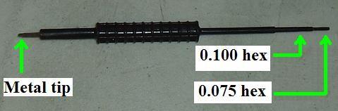
- You may need a plastic hexagonal tuning tool on some stations. These come in
standard sizes of 0.075 and 0.100 inches across. Motorola sells such tuning tools
for nearly $20 but they can be found for much cheaper.
Click here to see Motorola's
expensive tuning tool. Don't rush out to buy one until you know you've tried the
1/8-inch screwdriver first. If you do get one you might want to put a flap of tape on
it for two reasons: first, the tape makes it easier to count turns, second it keeps it
from rolling away.
- You'll need a 3/16-inch flat-blade screwdriver to align the receiver's mixer coils.
- You'll need a 5mm hexagonal (Allen) wrench to align the two VCOs, the receiver's
front-end coils, and the internal UHF filter/duplexer, if your station has one.
- You'll need a "tuning probe cable" to properly align the receiver's front-end coils
and the internal UHF filter/duplexer, if your station has one. There's a picture and
description of one in the MSF5000 Photo Tour article.
Motorola sold a tuning tool kit that contained the tuning probe cable, 5mm hex wrench,
and several other plastic and metal tuning tools. The MSF5000
Photo Tour article has a photo plus a better description.
Gathering Test Equipment:
You will need good test equipment if you want the station to meet specifications. That
old tube-type RF generator you bought in the 1960s just isn't going to hack it. I purchased
individual pieces of professional equipment, but most communications service monitors
have all the abilities you will need in one easy-to-carry unit. Either way, it could be
a substantial investment, even if you buy on the used market. If you don't have this
equipment, find someone who does who can either do the job for you or assist you. Most
people will be hesitant to loan out expensive and easily damaged test equipment. All it
takes is for you to transmit into the output port of a signal generator and it's toast. Likewise
the receive port of a service monitor.
You will need:
- An RF signal generator that covers the band of interest with a calibrated output level
that goes from below 0.1 microvolt up to nearly 1 volt into 50 ohms.
It needs Frequency Modulation capability at several frequencies, or the ability to utilize
an external audio oscillator, will also be required. You need this to align the receiver
front-end and the internal UHF filter/duplexer, if your station has one.
- A frequency counter that covers the band of interest and has an accuracy and display
ability down to ±100 Hz of the operating frequency. You need this to set the transmit
frequency reference oscillator.
- A way to measure FM deviation on the band of interest. You need this to set the
transmit deviation with PL / DPL.
- A way to measure the RF output power of the station on it's operating frequency and at
the appropriate power level. Either a Bird or CDI meter with the appropriate plug-in elements,
or a Telewave or equivalent multi-band, multi-power meter will do. Some of the Bird
"Termaline" dummy loads have built-in wattmeters.
- An RF dummy load capable of handling at least twice the output power of the station
at its operating frequency. Some of the Bird dummy loads also have built-in wattmeters.
Get a good one (Bird) that's fully shielded; don't waste your money on an inexpensive MFJ
dummy load. You need this to set the output power level and align the internal UHF
filter/duplexer.
- According to the alignment manual, you'll also need an RF voltmeter to align the
internal UHF filter/duplexer, but I've had better luck with a spectrum analyzer.
- An audio oscillator would be handy for a couple of alignment steps, but if your RF
signal generator has an audio source that it uses for modulation and has an adjustable
output level, that will most likely suffice. You need some audio source to set the wire
line audio levels.
- An AC voltmeter with full-scale ranges of 0.1V, 1V, and 10V will be useful to set
the wireline audio levels. Most digital multi-meters will work fine for this purpose.
You'll also need various coaxial cables with appropriate adapters to attach to the
transmitter and receiver antenna jacks on the station. I use RG400 (double-shielded)
cable (it's the size of RG-58) with male BNC connectors, plus the appropriate BNC to
N male adapters, for the receiver, and RG214 (double-shielded) cable (the size of RG-8)
with crimped-on male N connectors for the transmitter.
Motorola made two metering panels for the MSF5000 product line. Both have a
50 microamp meter, a meter polarity switch, a meter signal selector switch,
a loudspeaker, and an audio amplifier. The Radio Metering Panel (RMP) TLN2418A
unfortunately stops there. It's OK for alignment purposes but not much else. You
really want the Diagnostic Metering Panel (DMP) TLN2419A, which adds an array
of 64 LEDs that tell you the status of 64 logic signals inside the station.
You can also activate many of these signals manually through front-panel switches,
and this ability greatly simplifies the alignment procedure. You'll need two cables
that should come with either meter: a 40-pin flat cable for power, audio, and logic
signals that plugs into the expansion jack on top of the control tray, and an 8-pin
modular cable for metering that plugs into either the RX or TX metering jack on
the front of the RF Tray. A set of test probes should also be included but they usually
get lost and you're better off buying and using a digital multi-meter instead. Some people
prefer an analog (i.e. needle) multi-meter to the kit as it's easier to see the peak as
you adjust the coils. Photos of the DMP are in the MSF5000 Photo
Tour article and the manuals for each are available at the bottom of
the MSF and PURC Index Page. There's also a paragraph
towards the bottom of the index page describing a necessary modification to either metering
panel to fix a design flaw BEFORE you blow up your metering panel.
You could use an ordinary 50 microamp meter and a modular network cable to
make your own metering test set, however you'll eventually want a real MSF5000 DMP,
so start looking around for one.
Accessing The Station:
These stations are HEAVY: 150-300 pounds depending on the feature set and the RF
power level. Two people are required to safely move one and be careful, they are
top-heavy and will surprise you the first time you move one! I recommend you elevate the
station for servicing at least 2-3 feet above ground by putting it on three layers of cinder
block or up onto a stable work bench.
Use your 2135 key to unlock and remove the front door. Locate the RF Tray; it's
usually the lowest unit in the cabinet and it will have "MSF5000" printed on the front panel.
Refer to the MSF Photo Tour if necessary. Use a Torx wrench to remove the four screws
holding the front panel of the RF Tray to the cabinet side rails. Put your fingers into the two
spring-loaded plastic latches at the bottom corners of the RF Tray's front panel and slide
the latches toward the center of the station, then pull the RF Tray forward. It's on
equipment slides and should pull all the way out, about 8-9 inches.
The plastic control tray is mounted on top of the RF Tray. There may be a second
plastic expansion tray on top of the control tray; treat them as one assembly for now. To
access the top of the RF Tray or work on the control tray, first you have to unlatch the
control tray. On the left side there's a plastic latch. Push the top inward or pull the
bottom outward just a bit while lifting the left side of the plastic tray. Be very careful
as you lift it all the way up. There are three easily broken plastic hinges on the
right side that the tray pivots on. A sliding guide at the rear of the control tray will limit
the travel to just over 90 degrees. As long as you've extended the RF Tray all the way out,
the control tray will clear the RF power amplifier. You can now access the various
adjustments on the top of the RF Tray or even remove its top cover. This condition, where
the RF Tray is extended and the control tray is raised, is known as the "service position".
You may notice two large knobs in the rear corners of the top of the RF Tray. These
activate mechanical locks on the two VCOs to keep them from rattling around (and risk
damaging) when the station is being moved (TRANSIT position). The station will work
with the VCOs locked or unlocked, but they will float and be much less susceptible
to mechanical vibration if they're unlocked (OPERATE position). You can see these knobs
in the MSF Photo Tour.
Suggestion: add a label on the front of the RF Tray saying "Lock the VCOs before moving".
That label will also remind you to unlock them after moving.
When you're finished, carefully lower the control tray. Don't let it drop; the plastic
WILL break. Make sure none of the cables are in the way as you lower it.
Also make sure the sliding guide at the rear of the control tray doesn't bind or get
stuck because it WILL cause the control tray to twist and you'll very
likely break one or more of the three weak hinges on the right side of the control tray.
Lubricate the sliding guide if necessary. Secure the latch at the left side. Slide the RF
Tray back into the cabinet until the plastic latches in the lower corners lock it in place
then reinstall the four screws in the corners.
If you have to get to the power supply, you need to remove four screws holding the RF
power amplifier first, then tilt the RF power amplifier out and down. There are pivot pins
at the lower edge. Be careful; the PA weighs close to 40 pounds. The power supply is
behind it. There are several fuses on the distribution board at the top of the power
supply. Some stations have round glass fuses; others have flat blade (automotive-type)
ATO fuses. If that board has a shielded area, a slide switch, and a potentiometer, you've
got a battery-charging or battery-reverting power supply. No matter what supply you have
it's a good idea to put an extra half-dozen fuses in a zip-lock bag along with a magnet...
stick the magnet to an inside panel of the cabinet and you will have spare fuses at the
site.
Programming The Station:
Connect a dummy load to the transmitter or antenna output, just in case the station
wants to transmit. Apply power to the station.
Start your programming computer. Attach the RIB to the computer and turn them both
on. Plug the other cable into the station. Start the MSF5000 RSS program.
You should always read the existing code plug from the station and save it to disk
so you can restore the existing settings. Always use a unique name. I suggest a date
and possibly sequence number be used until you get a configuration that works to your
satisfaction. You can delete the intermediate files once you've got things working the
way you want. Always keep your first (original) programming file and label it as the original.
After making changes, save the code plug to disk with a different name, then write
the code plug to the station. Note that this happens in two phases: RSS sends the data
to the station where it is stored in RAM. RSS then tells the station to commit this to
EEPROM. The station automatically resets when this has completed.
This article takes you through most of the settings for a
UHF repeater. The VHF and 900 MHz stations are similar.
Aligning The Station:
The alignment section of the MSF5000 Instruction
Manual has been scanned and is available on repeater-builder. It's rather long
(48 pages) and has a few errors and omissions. You need to read it very thoroughly
and follow the steps precisely. Some steps are skipped for some bands. I'd suggest
you print the entire file and keep it near the station during alignment.
Perform all steps in each section exactly as they tell you to. Do not repeat a
step without starting from the beginning of that section. For example, when tuning
the receiver front end, adjust each coil going from left to right. Don't go back
and readjust one unless the procedure tells you to. Also, in some steps you will be
tuning for a dip or minimum. This should be very noticeable and you can rock the
tuning screw back and forth to find the lowest point. Keep the meter between 15 and
25 so you can see the dip.
When adjusting the receiver (RX VCO, pre-selector and injection filter, front
end), you will need a signal on the receiver's frequency and the meter cable will
be plugged into the RX METER jack on the front of the RF Tray. When adjusting the
transmitter (TX VCO), the meter cable will be plugged into the TX METER jack on the
front of the RF Tray. The MSF5000 meter is not needed to adjust the UHF internal
filter/duplexer nor for any of the electronic adjustments (mechanical potentiometers)
in the RF Tray.
If you will be tuning a UHF internal filter/duplexer, note that one important
instruction is absent from the alignment procedure: you need to connect the tuning
probe cable (the same one you used to align the receiver front end) to an RF
Millivoltmeter or spectrum analyzer as an indicating instrument. The probe end gets
inserted into the various holes in the filter/duplexer casting in the same way that
it gets inserted into the receiver front end.
If your UHF station has the internal filter/duplexer, you'll find it much easier
to access the connectors if you remove the metal cabinet from the station. Use the
Torx wrench to remove all of the bolts in the plastic top cover and remove the cover.
Then apply slight outward pressure to the front of the cabinet while slightly lifting
it up out of the grooves in the base. You can then bend the cabinet enough to clear
the connectors at the right side and entirely remove the cabinet.
The forward and reflected alarm trip points should not be adjusted on VHF or UHF
stations. On 800 and 900 MHz stations you can change these through the RSS service
screen. You may see steps that tell you to set a particular MUXBus bit. This can be
done through the RSS MUXBux screen or with a Diagnostic Metering Panel (DMP) by setting
the appropriate address and data bit with the rotary knob and toggle switches then
raise the "ENTER" switch to set that condition. Set the data switch off and raise
the "ENTER" switch to clear that condition.
Electronically Eraseable Potentiometers (EEPots) are three-terminal potentioneters
made up of two digital resistors with a common center point. As one increases the
other decreases. Each has 100 steps or values of 0 to 99. These are what the digital
station uses to adjust the audio and squelch levels. They can be accessed through
the RSS service screen or by using switches on the front of the station.
This article tells you how to adjust the EEPots. The
analog station has ordinary mechanical potentiometers for the various audio and
squelch levels. These are accessed through the front of the control tray.
Be careful when physically adjusting pots on the RF Tray. Don't push in too hard.
Some of the pots are not mounted well, mainly the ones you access through the front
panel.
The Modulation Compensation adjustment requires you to see the demodulated waveform.
An oscilloscope connected to a deviation meter will probably work, but due to the low
frequency utilized, a service monitor is much better for this procedure. It's not a
critical adjustment and can probably be ignored unless someone has replaced parts in
the RF Tray.
You can ignore the wire line adjustments unless you'll be using them to interface
an external repeater controller.
There are multiple squelch adjustments - these are particularly important. If you're
going to be using the internal controller to generate the CW ID, the station will not
send a CW ID if any of the squelches remain open. They must all be closed, whether
you're using them or not, to enable transmission of the internally generated CW ID.
The station will work fine in all other respects however.
Troubleshooting Error Codes:
The MSF5000 performs extensive diagnostics when powered up. If a problem is detected,
a code will appear in the display window. This file
decodes the errors and suggests possible corrective actions.
If the station has a real serious microprocessor error and it can't display an error
code, it will blink one of the LEDs on the front panel. Also, the stations can send alarms
out over the air as a sequence of beeps. There's a list
at the end of this file that tells you those LED patterns and beeps.
You can enable or disable over-the-air error reporting (beeping) with RSS. Similarly,
you can enable or disable audio diagnostics with RSS.
Converting A Base Station To A Repeater:
The MSF5000 can be configured as a base station (single antenna jack with a relay to
switch between the receiver and the transmitter) or a repeater. On the UHF repeaters,
Motorola provided a filter/duplexer and special cable inside the cabinet that allowed
the station to use one antenna for both functions. The special cables work, but just
barely. You're really better off with a real external duplexer. On all other bands
they utilized real pass/reject duplexers.
Base stations have a low-pass filter between the RF Power Amplifier (PA) and the
antenna relay. On VHF stations, the antenna relay is installed in this filter enclosure;
on UHF stations the filter is just a long tube with female N connectors at each end. You
want the filtering to still be effective so don't bypass it. You may have to take the VHF
filter enclosure apart to force the antenna relay into the TX position, or add a jumper
wire across its contacts, so the transmitter signal always comes out the other end.
To connect an external duplexer, the antenna relay and its cabling need to be replaced
with individual chassis-mount jacks and cables, and the relay power needs to be
disconnected. Leave the low-pass filter in place between the PA and the duplexer.
For UHF and higher stations, the receiver cable must have a right-angle male SMA
connector to mate with the input connector on the right side of the RF Tray. I believe
VHF stations need a straight male mini-UHF connector. RG400 coax is used because it's
double-shielded and has a stranded (flexible) inner conductor. This cable has to flex
when the RF Tray is extended. The other end has to terminate in a female N connector.
You may have problems finding such a connector that works with RG400 coax. If so,
install a female-to-female N bulkhead adapter in the station and terminate the receiver
cable with a male N connector.
The transmit cable just has to go between the output of the low-pass filter and a female
N connector on the side of the station. On UHF stations, the output of the low-pass filter
is a female N connector, so that end of your cable must be a male N connector. You could
use either RG214 or RG400 coax. The other end has to terminate in a female N connector.
Use a male N connector and a female-to-female N bulkhead adapter if necessary.
If your UHF station has the internal filter/duplexer, you might as well try to use it.
If not, get a good pass/reject duplexer with at least 4, prefferably 6 sections. There
may or may not be room inside the MSF5000 cabinet for it; if not, you might consider
mounting it to the rear of the cabinet like I did on my short station, or acquiring a
larger cabinet. Pull the top cover off, pull the metal cabinet off, mount some shelf
or L-brackets to the rear of the cabinet, reinstall the cabinet and top cover, and
mount the duplexer to the brackets. Alternately, you can mount the brackets and
duplexer to the top cover.
Interfacing Options:
There are several connectors available for interfacing external repeater controllers.
There's an entire section on interfacing on the MSF and PURC
Index Page and there are nearly a dozen such articles.
At a minimum you should read this one as it
describes all the signals on all the connectors. There are also articles that summarize
where you can find common signals required for most repeater controllers,
for the analog and
digital stations.
Making It FCC-Legal:
The internal controller of the analog station is preset to identify every 15 minutes
and can't be changed by station programming. This would violate FCC rules Part 97.119,
which say (in part):
(a) Each amateur station, except a space station or telecommand station,
must transmit its assigned call sign on its transmitting channel at the end of each
communication, and at least every 10 minutes during a communication, for the purpose
of clearly making the source of the transmissions from the station known to those
receiving the transmissions. No station may transmit unidentified communications or
signals, or transmit as the station call sign, any call sign not authorized to the
station.
It should be psssible to hack (modify) the program PROM of the analog station to change the
IDer timing, but as far as I know nobody has. If anybody does, we'll be happy post the
modification information. Just contact the author.
UPDATE: There is now a ham-written program that modifies the analog station
code plug EPROM image file and allows changing the all of the unchangeable fields.
They improved things for the digital stations. The speed, tone frequency, and interval
timing CAN be specified through RSS, so the internal controller will be
satisfactory for identification in amateur repeater use. The CW ID is "polite" in that it
will not identify if the repeater is in use. This means that a long-winded transmission
could result in the interval exceeding 10 minutes. I'd suggest you set the station interval
to 8 minutes. Also you should know that Motorola repeaters usually identify without PL/DPL
present on the transmitted signal. If you lengthen the repeater hang time to 10-12
seconds, the CW ID will be transmitted with PL/DPL due to the hang time.
Most of the RSS settings necessary for a repeater are detailed
here
The repeater must be able to be shut down in the event of improper use or operation, or
if an FCC agent tells you to do so. Most repeater controllers use Dual-Tone Multi-Frequency
(DTMF or Touch-Tone) signaling for this purpose by monitoring the repeater input for
control codes. Other methods such as phone lines, the Internet, or a separate control
receiver are also acceptable.
A long time ago (1980s and earlier), any repeater could be controlled over the air but
only if the control frequency was 220 MHz or higher, which implied a separate receiver
just for control. That restriction has been removed, so you can control any MSF5000
amateur repeater over the air, using methods described above. If you plan on using just
the internal controller, you still need a way to turn the repeater on and off when
necessary. This can be done with a separate DTMF decoder; this
article shows you one way to do it. You can also connect such a device to the wire
line connector and program the "External PTT Input" (J2 pin 12) to enable/disable the
transmitter. Details about how to program this
pin can be found in the "Programming Tricks" section of this article.
Protecting The Station:
There's a Metric threaded stud on the side of the station. Connect that to the building
ground system with some #4 stranded wire or copper strap. Use a lightning arrestor of
some sort, such as AlphaDelta or Polyphaser. Make sure it has connectors appropriate for
the frequency and power; I prefer N male and N female. Each company makes products for
various bands; get one that will do the job for your repeater. Ground this to the same
point that the station ground goes to. Ideally, the antenna coax will have its own
lightning arrestor at the point where it enters the building, but not every site will be
set up that way.
The MSF5000 power supply uses a ferro-resonant self-regulating transformer that is
very forgiving to surges and changes in voltage. Due to the power these stations draw
from the AC line, you would need a commercial surge protector. The little ones that you
plug into the wall or exist in some outlet strips just won't do the job.
These stations are heavy - over 100 pounds. Most of the weight is at the top, in
the power supply and power amplifier. To move is safely you need two people.
The station should be installed on a level surface. If possible, try to put it
against a wall and add a strap to make sure it stays vertical. This strap will
also serve as a deterrent against anyone moving the station.
The switches and knobs that protrude from the control tray are fragile. There's not
much clearance between them and the inside of the front door and most parts are No
Longer Available. Don't lay the station down on its front or push in on the front door.
Make sure there's a printed copy of the FCC license bearing the repeater's call sign
posted on the station or in its immediate vicinity. This should also contain emergency
contact information, including a phone number, incase there's a disaster at the site or
your equipment is causing interference.
Powering The Station:
Some VHF and UHF stations come with a battery-charging or battery-reverting power
supply. These require one or two automotive-style lead-acid batteries and appropriate
FUSED cables. The station will have two, three, or four Anderson PowerPole connectors
on the side for this purpose. VHF stations running more than 25 watts need 28V and 14V
power sources, hence two batteries. All other stations run on just 14V, hence one battery.
The power supplies in these stations will work better if batteries are attached, but you
don't need them in most cases. Without the batteries, when the transmitter is keyed, the
voltage will drop by 1-2 volts but will slowly recover. The output power control circuit
will adjust for the lower voltage. This article describes how
the two batteries are wired on the VHF stations.
These supplies are supposed to also charge the batteries, however you may want to
employ an external battery charger (or two) on these stations. On stations with two
batteries, use one 12V charger per battery, otherwise one battery could overcharge and
the other could undercharge. There is an article on the MSF index page on this.
These stations draw a lot of power from the AC line. For this reason, you probably
don't want to run one on a UPS, because you'd need a large unit capable of 1400 VA for
a long period for most stations. The MSF power supply is bullet-proof and will survive
most AC line problems, but the price you pay for that resiliency is poor efficiency.
For the same reason, expect your electric bill to increase when you install an
MSF5000. If you're running it at home, you will see an increase in usage and you'll
have to pay for it. If your site offers free electricity, thank the radio gods. If not,
be prepared for the increase. Your page maintainer has seen an MSF that was
modified... a pair of switching power supplies replaced the original supply.
Miscellaneous Items:
A lot of documentation for these stations can be found on the MSF and PURC Index
Page in the Manual Library section. There's not much for the VHF stations, but both
the analog and digital UHF stations are well-covered. Once Motorola came out with the
digital stations, they reduced the contents of the manuals and only provided full
schematics for the Control Tray and most of the RF Tray. The power supplies were moved
to a separate manual and several pieces have been scanned and uploaded. The RF power
amplifiers are essentially non-user-serviceable because the modules are No Longer
Available from Motorola and they stopped detailing the parts and schematics.
The power supply, power amplifier, internal UHF filter/duplexer, and most of the RF
Tray on an analog station are identical to those used on a digital station and can be
swapped if necessary. The control tray is totally different, as is the interconnect
board under the RF Tray. This article describes how you
can install a digital control tray in an analog station.
The internal filter/duplexer on the UHF stations is actually two separate band-pass
filters that serve to reduce the out-of-band emissions from the RF Power Amplifier.
The three-section (input) filter is installed between the Intermediate Power Amplifier
(IPA) output in the RF Tray and the RF Power Amplifier (PA) input at the top of the station.
The four-section (output) filter is installed between the RF PA output and the antenna
connector. These filters are tuned using a method similar to tuning the receiver front
end, where you peak the first coil then dip the remaining ones. The amount of loss in
these filters is critical. The system can tolerate only about 0.5dB per section (1.5dB
for the input filter, 2.0dB for the output filter). If there's too much loss, the power
control circuit in the station will indicate a fault, either through the "PA LOW" LED
or a displayed error code on the control tray, or beep over the air.
Contact Information:
The author can be contacted at: his-callsign [ at ] comcast [ dot ] net.
Up one level (MSF index)
Up two levels (Moto index)
Back to Home
This article was conceived Sept 12 2014.
This web page, this web site, the information presented in and on its pages and
in these modifications and conversions is © Copyrighted 1995 and (date of
last update) by Kevin Custer W3KKC and multiple originating authors. All Rights
Reserved, including that of paper and web publication elsewhere.