What happened to Marconi? and IFR??? Marconi was sold to IFR Systems Inc. in
1998. In 2002 Aeroflex Inc. (a New York-based holding company) bought IFR for
about $60 million and folded it into their other holdings as "Aeroflex Test Solutions" (ATS)
which no longer exists excapt as a page
at Wikipedia. The ifrsys.com web site soon evaporated. In late 2014
ATS was bought by Cobham Advanced Electronic Solutions and then in 2017 CAES
was renamed to Viavi Solutions... Their
web site no longer has any info on any Marconi or IFR equipment as the current
business has turned away from general instrument manufacture. Instead, Viavi now focuses
on 5G (cellular) telecommunications equipment and the
CAES web site. now lands at https://www.honeywellaerospace.com.
IFR made a lot more models that we have listed below. We have very little on Marconi equipment. What you see below
is all that we were given.
If you don't see what you need here, then we weren't given it.
Donations of manual files, photos, or any other useful information are gratefully accepted.
One manual we'd really like to have is the FM/AM-1200 Super S Service Manual.
(or even the loan of a paper manual that we can have scanned and then returned to you)
You will see references in the manuals below to the "S/A" units. There is
no actual unit called the (whatever-model-number)S/A, it's a collective abbreviation. One
manual would be for both the (for example) IFR-1200 model, IFR-1200A model and the
IFR-1200S model. The IFR-1200 was the basic model, the IFR-1200A-model added the
spectrum analyzer and the IFR-1200S-model added the tracking generator.
And in response to several emails, no, I don't know if the basic model can be upgraded to the
A-model, or if the A-model can be upgraded to an S-model, where to get parts, or how to do it.
Many of the older IFRs are having aging problems. Aged capacitors and display issues
are the most visible. There is an article in the IFR-1200 section below on capacitor replacement.
When the 1200 series power supplies fail one failure mode is that they tend to burn up the
PC board as they die. Another failure mode is that the +5 volt regular shorts and applies
+16 volts to the +5 volt output. That will destroy almost every IC chip in the unit,
and many are pure unobtanium. Jay Hennigan WB6RDV designed a drop-in replacement
power supply using modern parts and there is an article on it below in the 1200 section.
A lot of older IFRs use blue circuit boards. These boards are a type of plastic and are
from the pre-fiberglass era. The blue board material itself is sensitive to heat, and the
glue bonding the copper traces onto the blue board was weak and heat sensitive even
when the boards were new, and the glue has become more sensitive with age.
You must do ANY soldering with great care and VERY quickly to avoid de-laminating
the board. Just expect that traces will lift if you have to any soldering at all on a blue
board. This is the sad voice of experience.
The original paint used on the IFR 500 / 1200 / 1500 / etc.
products (and maybe the others) was Sherwin Williams Profile Gray (Polane) which a a 2 part
paint / epoxy.
Thanks to Alex Szuski KD6VPH for this tidbit of information.
One of the companies that services IFR-500s and IFR-1200s is KG electronics in Wichita Kansas.
Contact Kurt Graber at 316-773-0948 or kurtgraber //at// yahoo //dot// com or visit their web
site at http://kgelectronics.com (an off-site
pointer, will open in a new browser tab)
I don't know of a service company for any other model(s). Please let the page maintainer know if
you find one and he'll update this paragraph.
Some IFR models (like the IFR-500) use BCD encoding thumbwheel switches for frequency
setting, one switch per digit. BE VERY GENTLE WITH THEM!!!
The first symptom of switch failure is that the switches will drop a bit (the bits have values of 1,
2, 4 and 8). For example, is you set the unit to generate on 449 MHz and it generates on
448 then you've dropped the "1" bit in that digit position. If it generates on 441 then
you've dropped the "8" bit. If you set it to 446 and it shows up on 442 then you've
dropped the "4" bit.
While the examples above describe the MHz digit this failure can happen on any digit position.
To the best of my knowledge the switches are orphans (no longer available) - there were
two manufacturers (IDEC and Unimax) and both are no more. If anyone comes up
with a substitute please let us know, we'll add it here.
If anyone has any information on an alternate switch or switch assembly that could
replace them, please let the page maintainer and and he will update this pragraph
(please let Kurt know also).
The Option 4 battery details depended on the model, and many of the IFR units
used a 5-Amp-hour lead-acid battery pack. Unless you NEED the battery
operation feature I suggest you remove the battery (keep the harness with the Molex
connector). The lead-acid batteries have a finite life and the battery can
swell up and leak, and the electrolyte can corode the internals. I lucked
out - both my IFR-500 and IFR-1200 had dead battery packs in them when I
acquired them, and neither one had leaked. I removed them just for
weight saving. If your unit has the battery installed you can chose to
keep it or remove it. If you keep it then look up how to read the battery
date code on Google and label the front of your unit with a replace-on date.
You will want to replace the battery every two to three years.
The optional battery pack in the IFR-500 consists of six Gates/Hawker
Cyclon/Enersys 0800-0004 cells in series in a plastic case. These are sealed lead-acid
2 volts cells rated at 5 amp-hours and the pack adds 6 pounds
of weight to the unit. A good pack at full charge provided about two hours
of operation. Surprisingly, replacements are available from Amazon! (at
the time of this writing) Look here:
https://www.amazon.com/Enersys-Hawker-Cyclon-0800-0004-Battery/dp/B0002ZR6DC. (off-site pointer, will open in a new browser tab).
The optional battery pack in the IFR-1200 is a single sealed lead-acid unit
of 12 volts at 5 Amp-Hours and it added about 3 and a half pounds
of weight. The modern replacement is a
Power-Sonic PS-1250 with T2 size (one-quarter-inch) terminals.
BE CAREFUL, I used to order this battery for alarm panels, and my experience
on multiple orders is that the people at Amazon do NOT know the difference
between the T1 (narrow) and T2 (standard 1/4 inch) terminals. The battery
cable harness in your IFR wants the T2 terminals!
I've also used ADI Global
for the lead-acid batteries. They are a wholesale distributor of low voltage (security,
audio-visual and networking) products with
over
20 warehouses nationwide. If there is a warehouse near you it's worth
visiting, they have a LOT of interesting stuff (some alarm products require
a license to purchase).
If you chose to replace the lead-acid pack with a lithium based battery (much lighter!)
you will have to either replace the charger circuit with a different design or disable
the charger and use a different charger. You could easily fit a Bioenno LiPo pack
and it's charger into the space that had the old lead-acid battery.
The page maintainer has needed to use his IFRs away from mains power only three
times in the last 15 years and uses an external 12 volt battery pack (a
Bioenno Power 20 Amp-Hour LiPo built into a Harbor Freight
30 caliber plastic ammo box) and plugs it into the exernal DC input on the
back of the IFR. A commercial version of that box is
here.
The Option 5 amplifier was an external device that plugged into the front panel
RF output jack and the adjacent +12 volt DC bananna jack. They
are rare and expensive when found as not many of the original purchasers of the units
included that option. As of the time of this writing Steve Dold W6KCS makes an
excellent exact
aftermarket replacement. (off-site pointer,
will open in a new browser tab)
Option 9: Field and Travel Padded Carrying Case Included.
Anyone know who made them for IFR? Or of a suitable source? Or of an alternative?
The page maintainer looked for a padded case for his 1200 for several years, then found
a well-used one for an IFR-1000 and used it for about a year, then was given a real 1200
travel case. If anyone needs a 1000 travel case just contact him... first come, first served.
The Option 10 DVM was included in all units after serial number 9267. Can anyone confirm?
The Option 12 Tracking Generator is not a field installable option. If you ever plan
on tuning a cavity or a duplexer then you need to find a service monitor that was built
with with it. Kurt sells fully reconditioned 1200S and 1200superS units with a warranty.
Option 14 added the LTR Trunking protocol, and depending on the firmware version
may have been wide open or limited to only the first 200 channels of the 800 MHz
band. Can anyone share some details?
Option 15: Cellular AMPS (Advanced Mobile Phone System) was the first-generation analog
cellular standard and was introduced in 1983. It established the hexagonal cell architecture and
frequency reuse concepts that define modern mobile networks. It used Frequency Division
Multiple Access (FDMA) on 30 KHz wide channels with uplinks from 824–849 MHz) and
downlinks from 869–894 MHz.
Option 16: Cellular ETACS (Extended Total Access Communication System). This was a
first-generation analog cellular mobile phone system used in the UK and parts of Europe. It
used Frequency Division Duplexing (FDD) on 25 KHz channel spacing with uplinks
from 872-905 MHz and downlinks from 917-950 MHz. It utilized 42 dedicated
control channels for call setup, paging, and handoff. It was replaced by GSM around 2001.
On some of the equipment below, we couldn't get the real IFR docs but were given the
equivalent military docs. If anyone has manuals (IFR or military) we don't have please send
them in and we'll post them here.
Note that the AN/GRM-114 is the military designation for the IFR-one-thousand-S and
the AN/GRM-114A is a different piece of equiment - the eleven-hundred-S.
Note that some are TM Technical Manuals and others are TB Technical Bulletins.

|
If you are curious how much your IFR cost when new then this may be of interest to you:
IFR Products Price List, April 1,
1986 1.2 MB PDF provided by Alex Szuski KD6VPH
And by the way, $5000 in 1986 is equivalent to over $14,500 in 2025 – see the
CPI Inflation Calculator. (off-site pointer, opens in a new browser tab)
|

|
The IFR500, 1000, 1100 and 1200 were developed in the days when wideband was 30 KHz
channel spacing and narrowbandwas 15 KHz channel spacing. They are still quite usable
on 5 KHz and 2.5 KHz signals.
|
|
|
The page maintainer needed to research replacement rubber feet for his 500 and 1200 units.
If anyone has better information he;d be willing to update this paragraph, however
the closest replacements he could find for the feet that are on the bottom of the unit are from
McMaster-Carr. (all
pointers in this paragraph are off-site pointers and open in a new browser tab).
McMaster-Carr is an industrial supplier with warehouses in Atlanta, Chicago, Cleveland, Los
Angeles and New Jersey however they will sell to the public. Item # 8884T21 was the closest.
(local copy). They
come in a package of 10 for about US$6.50 (late 2024 price). The original ones that IFR used
have a metal washer inside and the 8884T21 does not. They are not really needed
however I salvaged the washers from the old deteriorated ones and reused them.
The 500 and 1200 are the only models that I have access to, I suspect that the other models
used the same feet.
|
|
|
Jay Hennigan WB6RDV designed a drop-in replacement power supply using
modern parts and there is an article on it below in the 1200 section.
|
| |
FM / AM-500/A documentation and articles:
|
|
|
FM/AM-500/A Brochhure (4 pages) 901 KB PDF
|
|
|
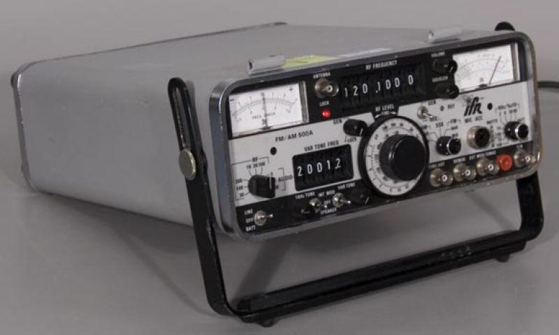
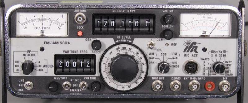
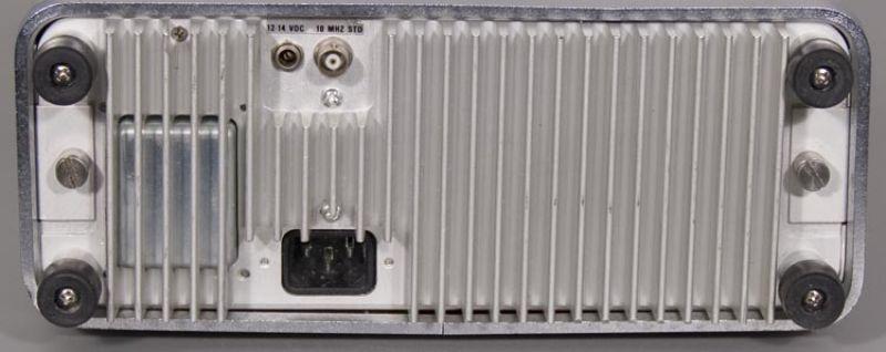
Exterior photos:
Photo 1
Photo 2
Photo 3
Photo 4
Your page maintainer has a 500A that showed up without the metal cover.
If anyone has an extra one he'd like to acquire it.
|
|
|
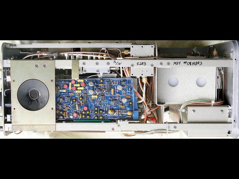
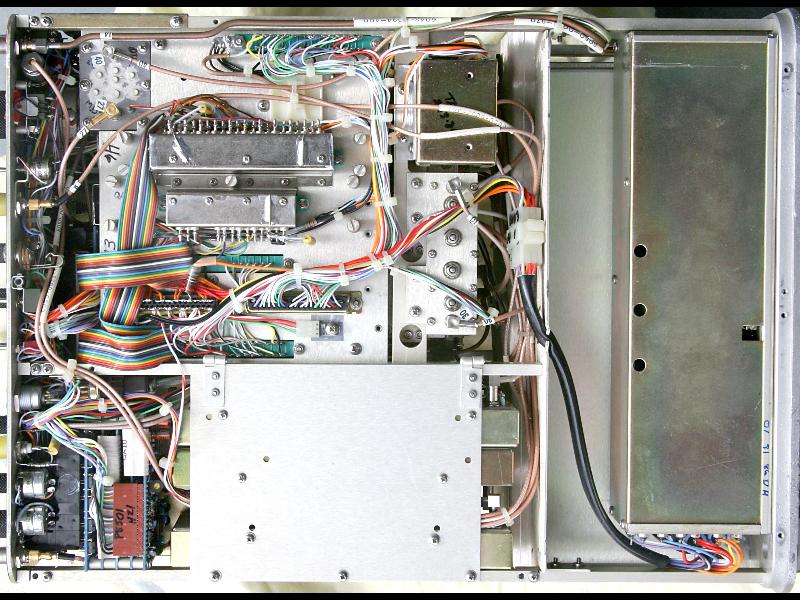
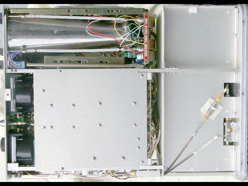
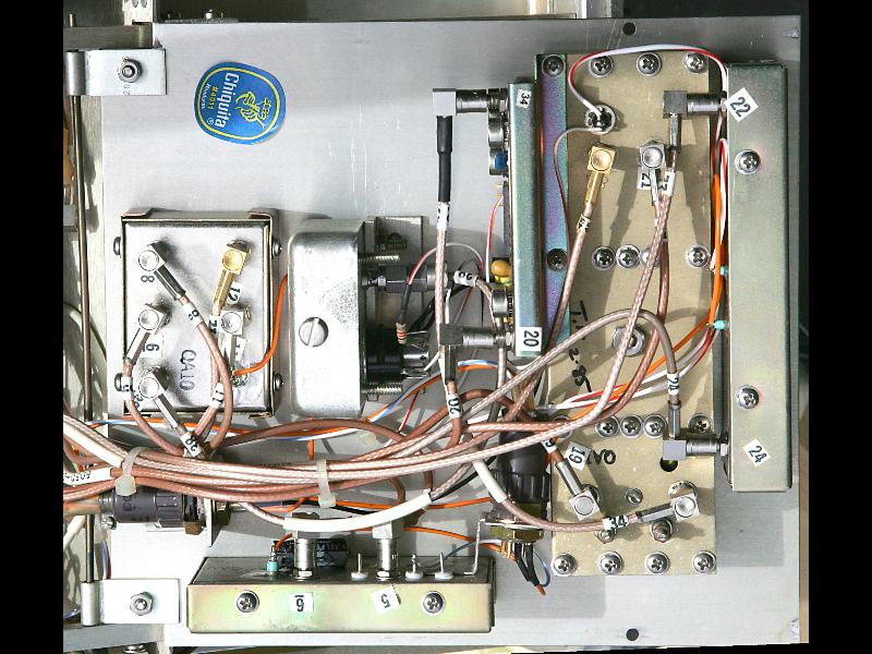
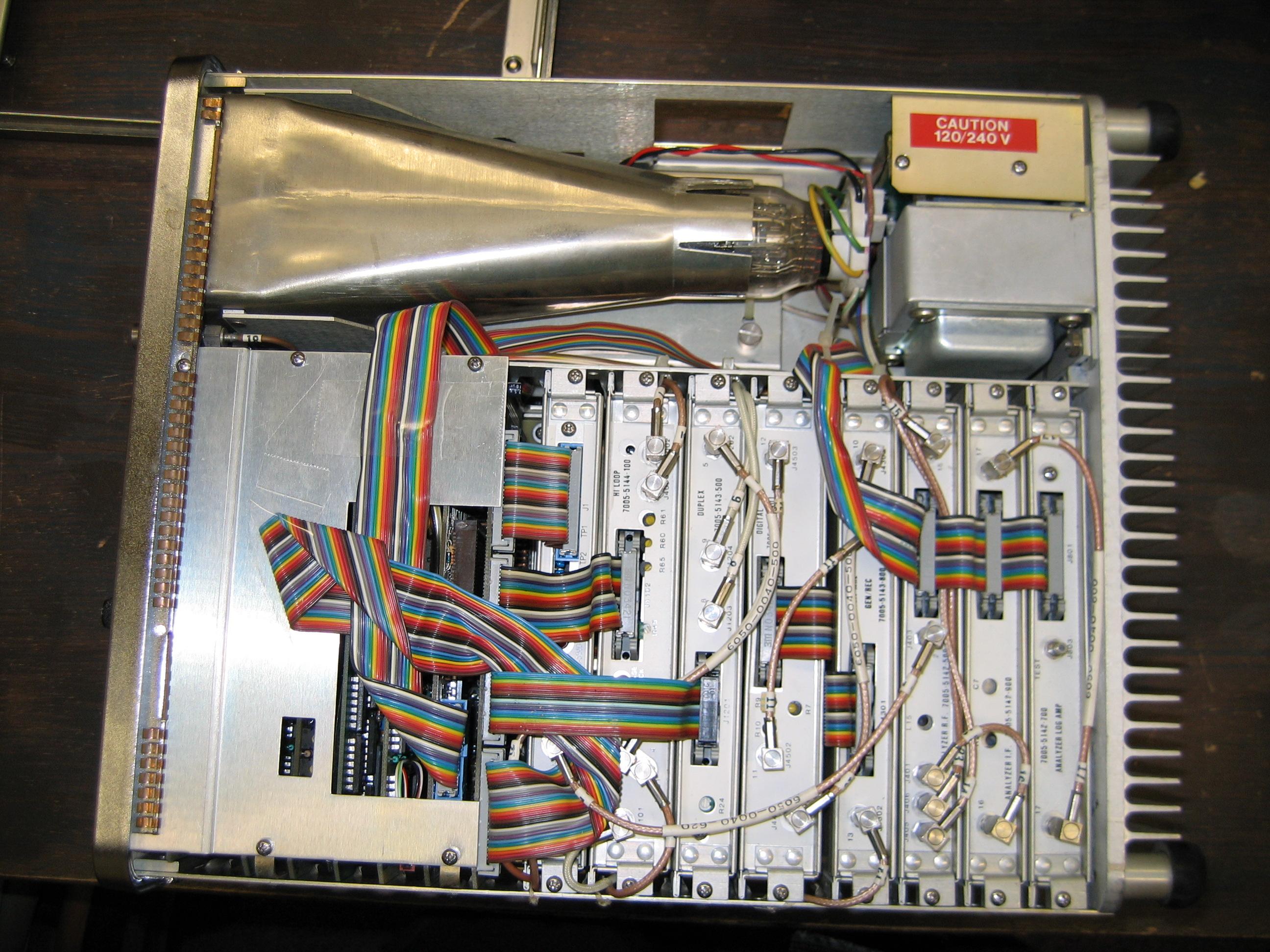
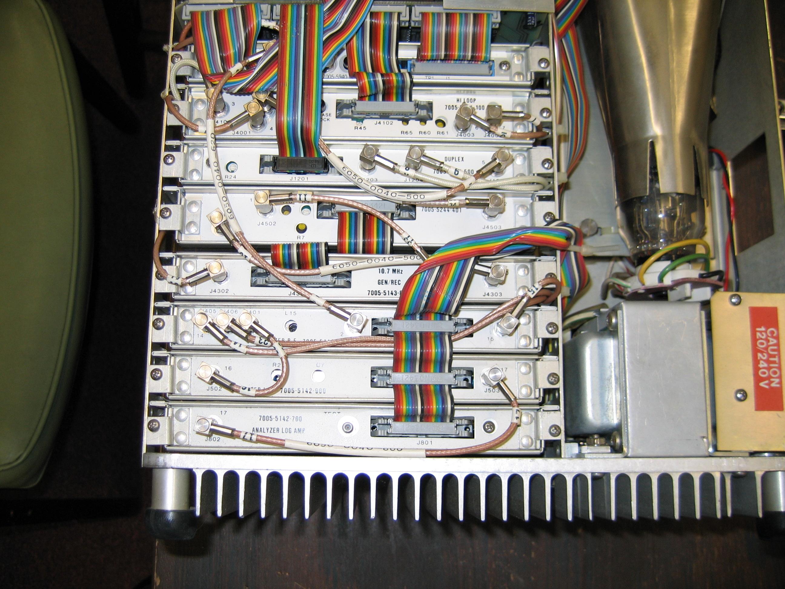
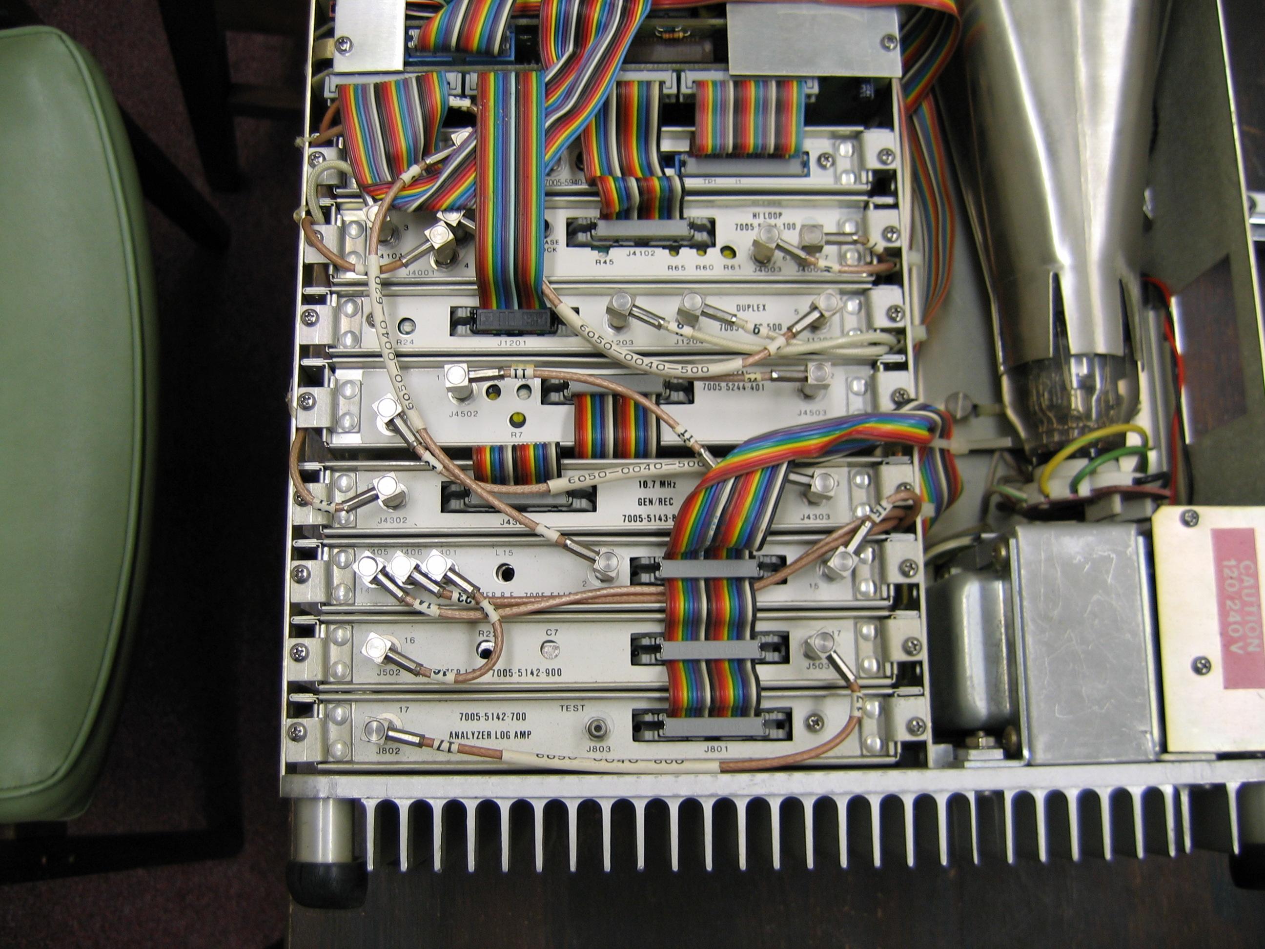
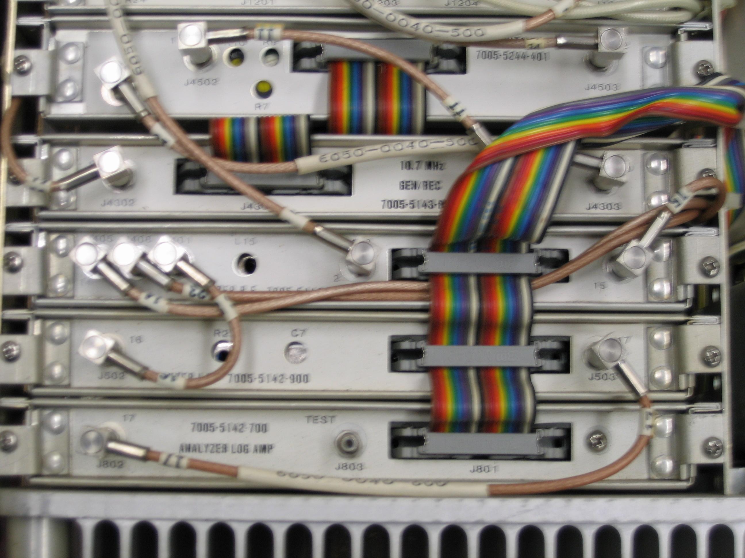
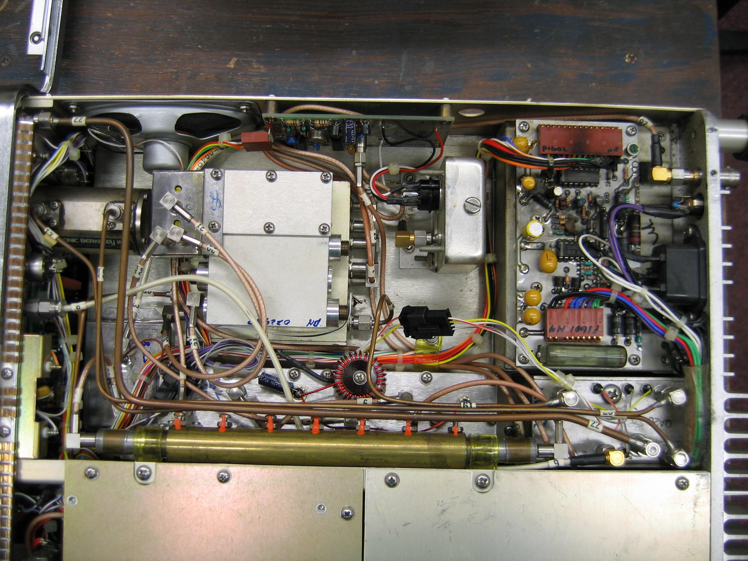
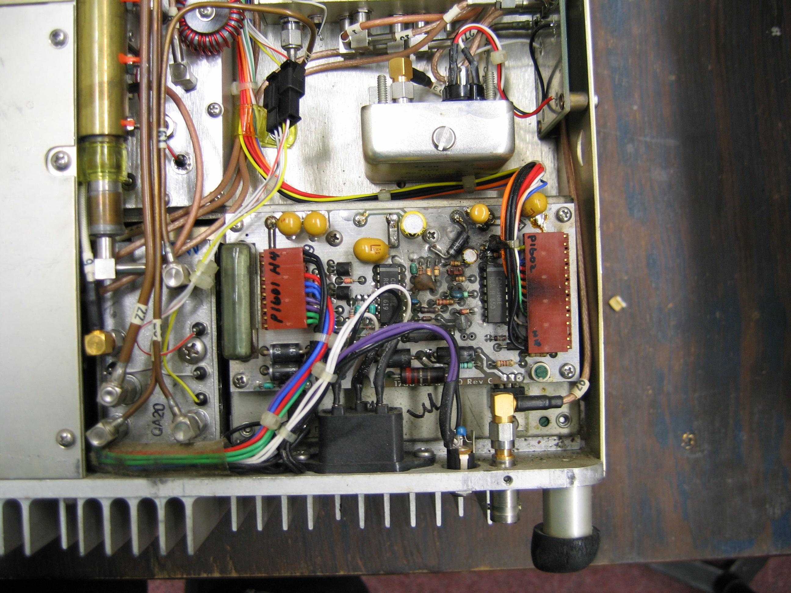
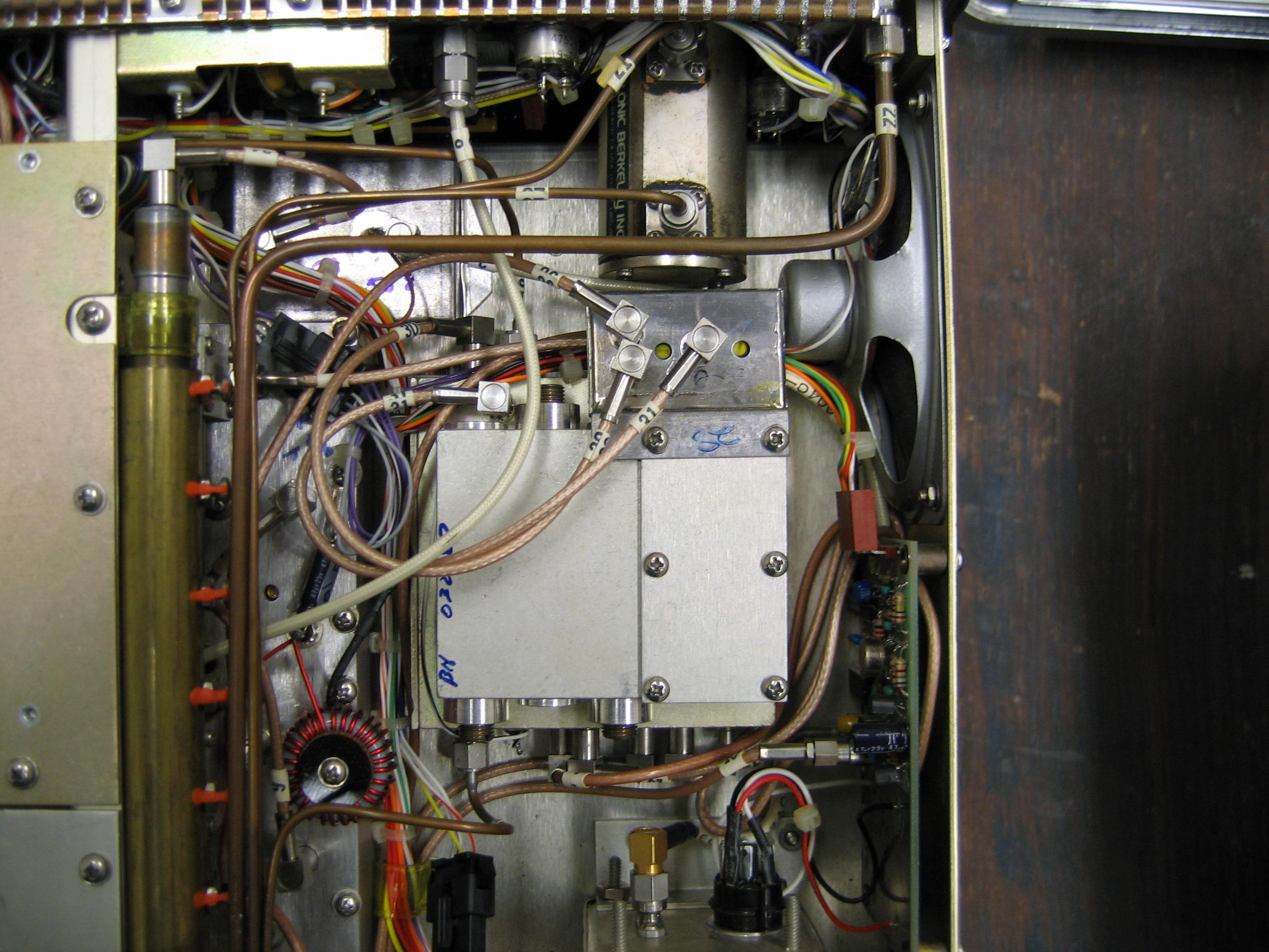
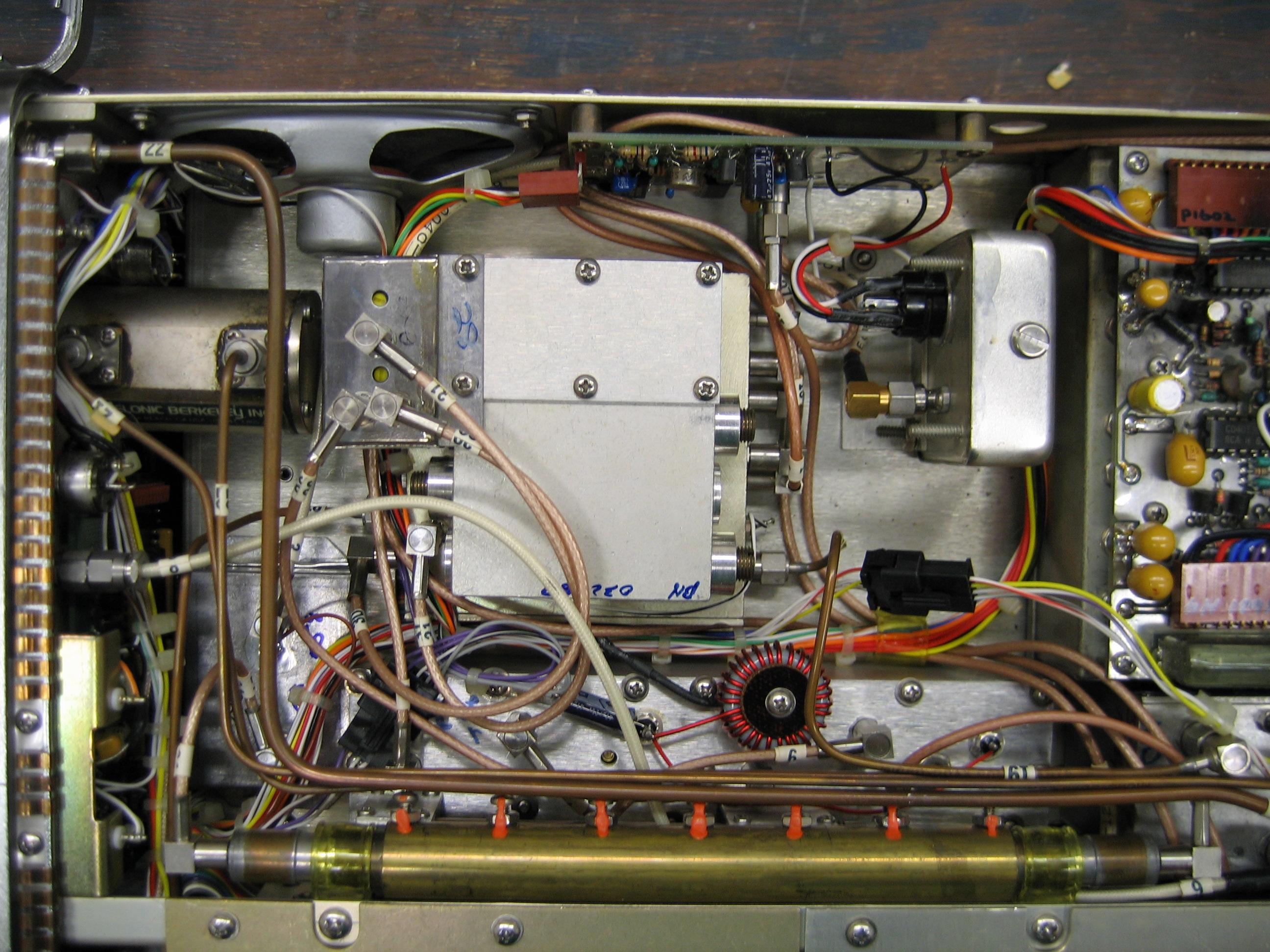
Interior photos courtesy of Hans Ronchetti in Australia:
Photo 1
Photo 2
Photo 3
Photo 4
Photo 5
Photo 6
|
|
|
FM/AM-500/A Service Monitor
Maintenance Manual 9.3 MB PDF
|
|
|
FM/AM-500/A Service Monitor
Maintenance Manual - Version 3A 16.92 MB PDF
|
|
|
FM/AM-500/A Service Monitor
Operation Manual 1.8 MB PDF
|
|
|
FM/AM-500/A Service Monitor
Operator's Guide 3.4 MB PDF
This PDF is courtesy of Randy Munro VE3OGB, forwarded by Bryan Boyle WB0YLE.
|
|
|
FM/AM-500/A Replacing Electrolytic
Capacitors Guide 133 kB PDF by Alex Szuski KD6VPH
|
| |
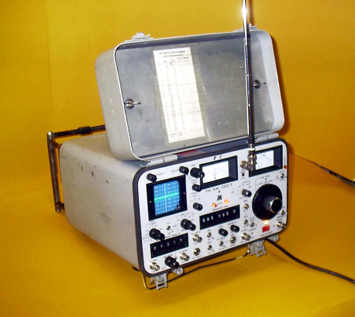
FM / AM-1000A/S or AN/GRM-114 documentation and articles:
|
|
|
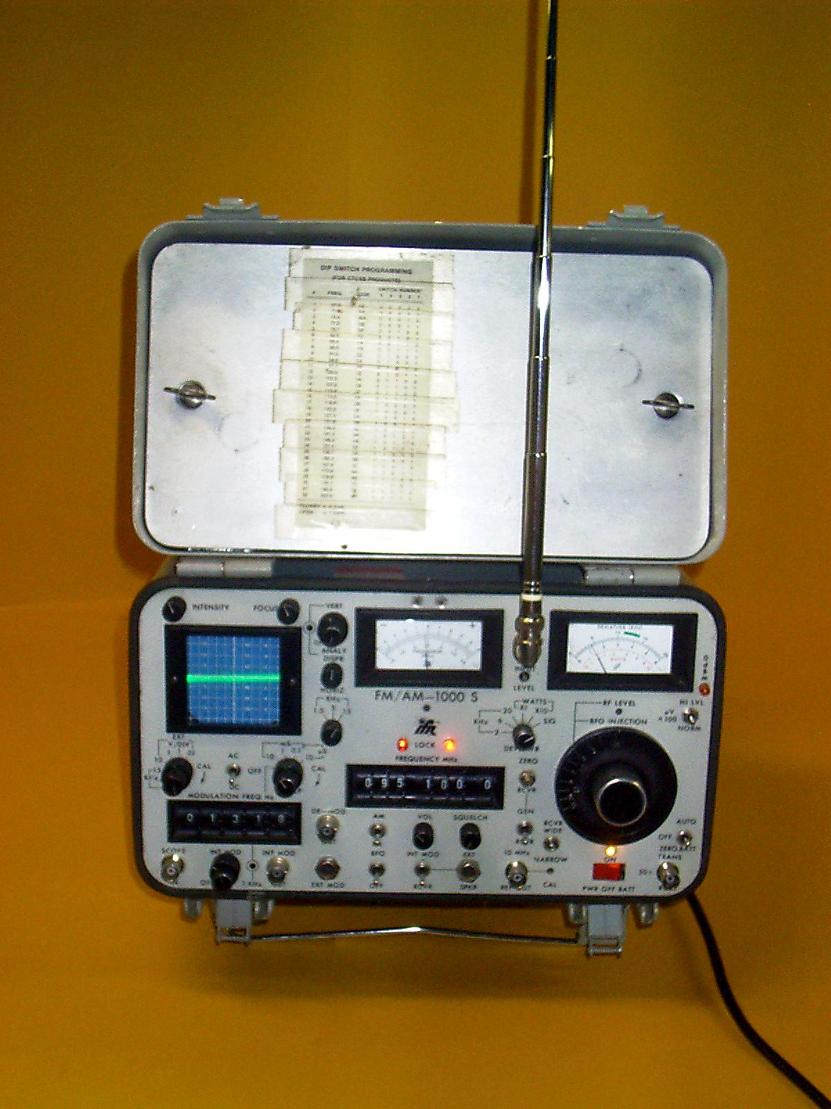
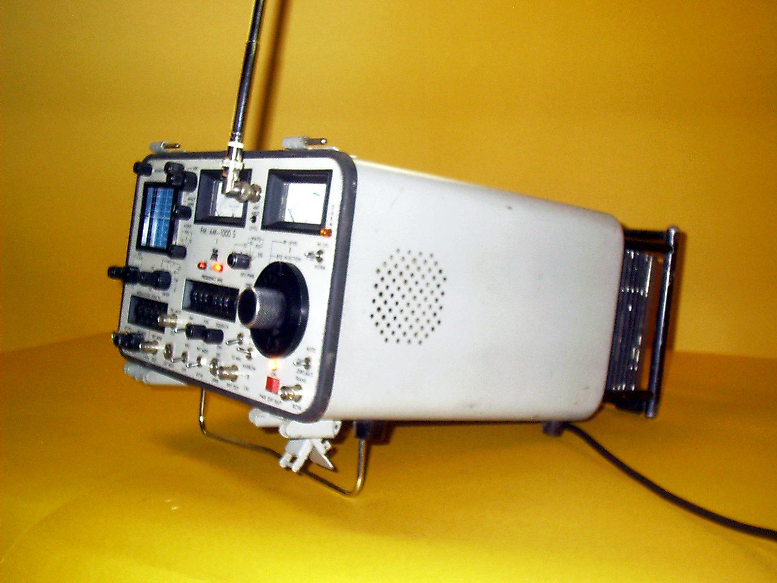
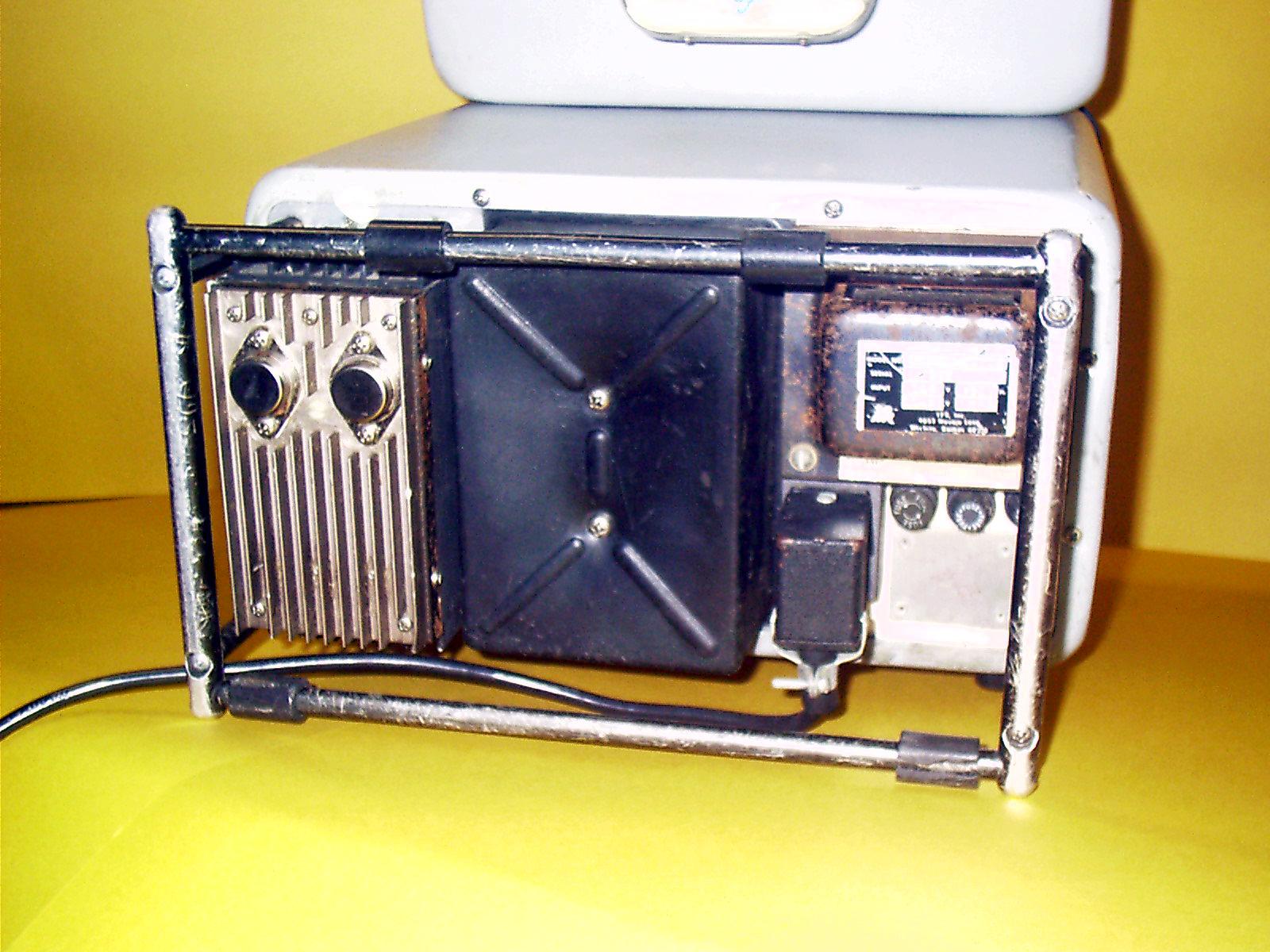
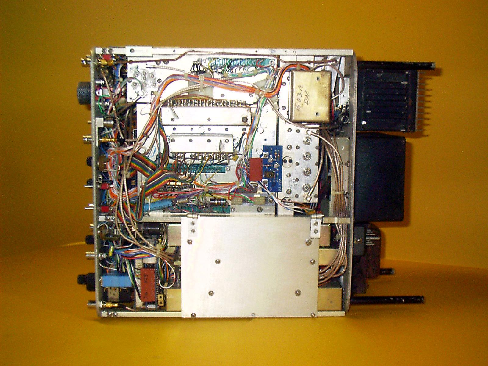
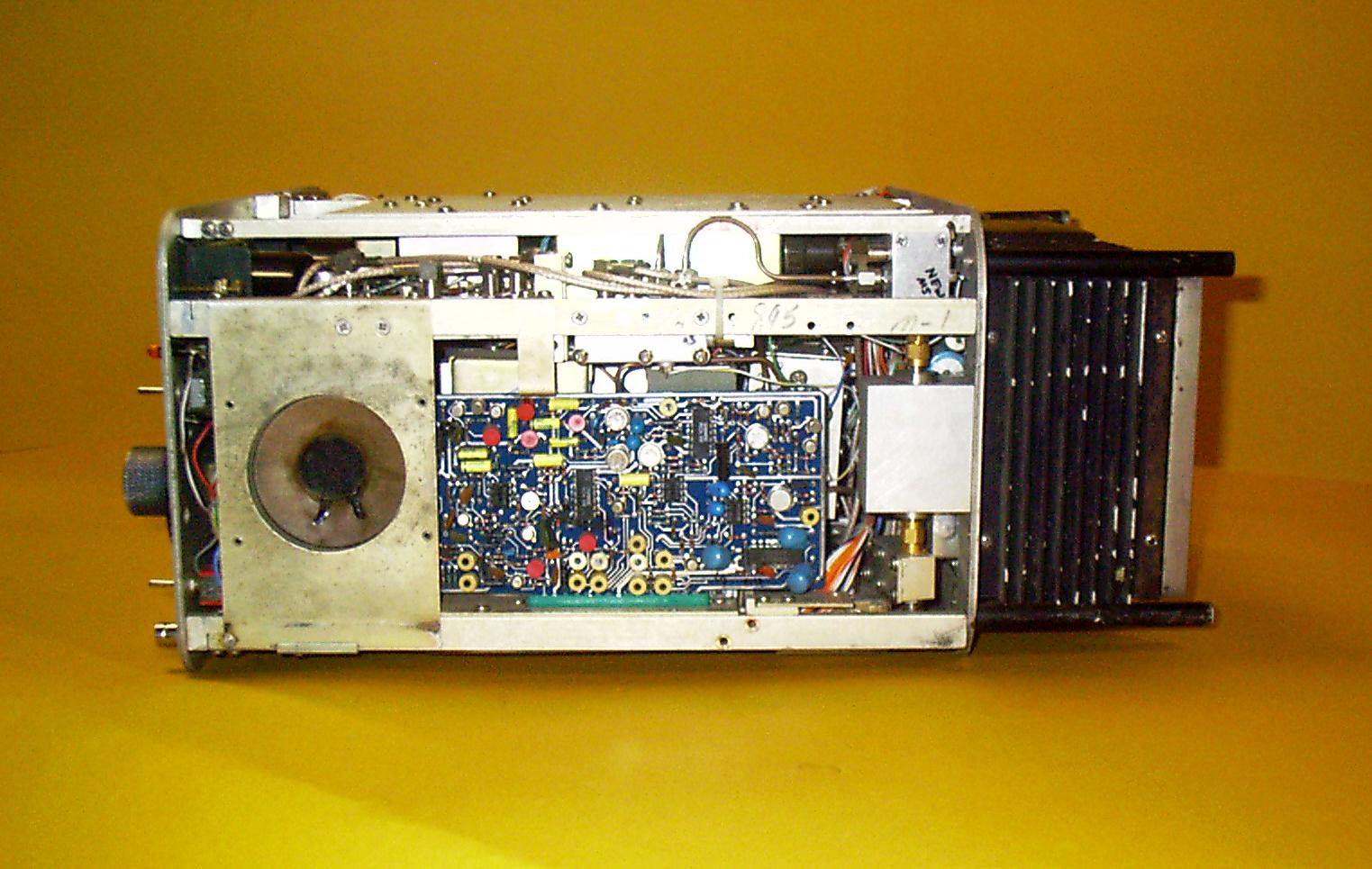
Photos courtesy of Charles Schmell KS3Z:
Front
Left Side
Rear
And one extra...
Inside Bottom
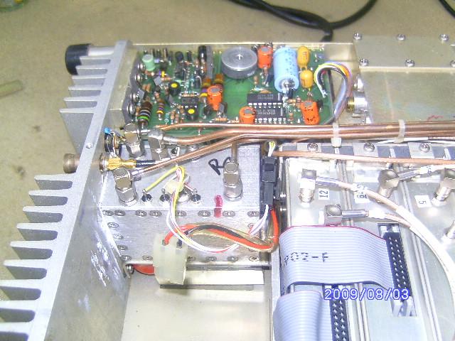
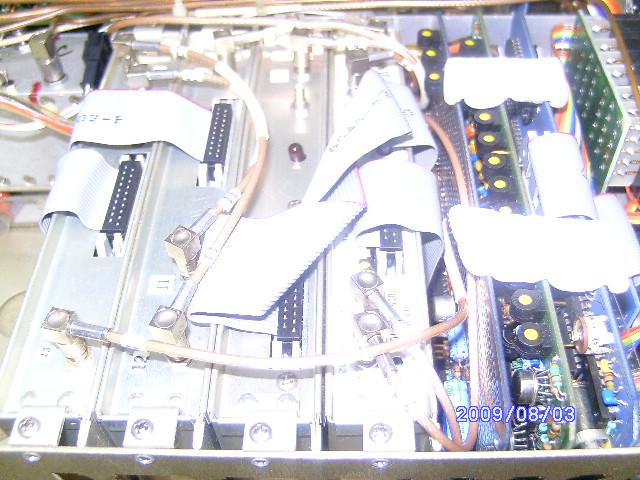
Inside Left Side
Inside Right side
|
|
|
FM/AM-1000S Operator's Guide
(s/n 108 and above) Dated 1980 894 kB PDF
|
|
|
FM/AM-1000S Operation
Manual Dated 5-29-1980 9.6 MB PDF
|
|
|
FM/AM-1000A Service
Manual Manual part number 1-23-0610, dated July 1978 26.5 MB PDF
|
|
|
FM/AM-1000S/A Sales
Brochure 2 MB PDF courtesy of Carl VA2CMB
|
|
|
FM/AM-1000S/A Service Notes Part 1 By
John Kuivinen WB6IQS 2.5 MB PDF
|
|
|
FM/AM-1000S/A Service Notes Part 2 By
John Kuivinen WB6IQS 545 kB PDF
|
|
|
FM/AM-1000S Operator's and Maintenance
Manual 10 MB PDF
This is actually the military manual TM 11-6625-3016-14, dated 18-Jun-1982, for Test Set,
Radio AN/GRM-114
|
| |
FM / AM-1100A/S documentation and articles:
|
|
|
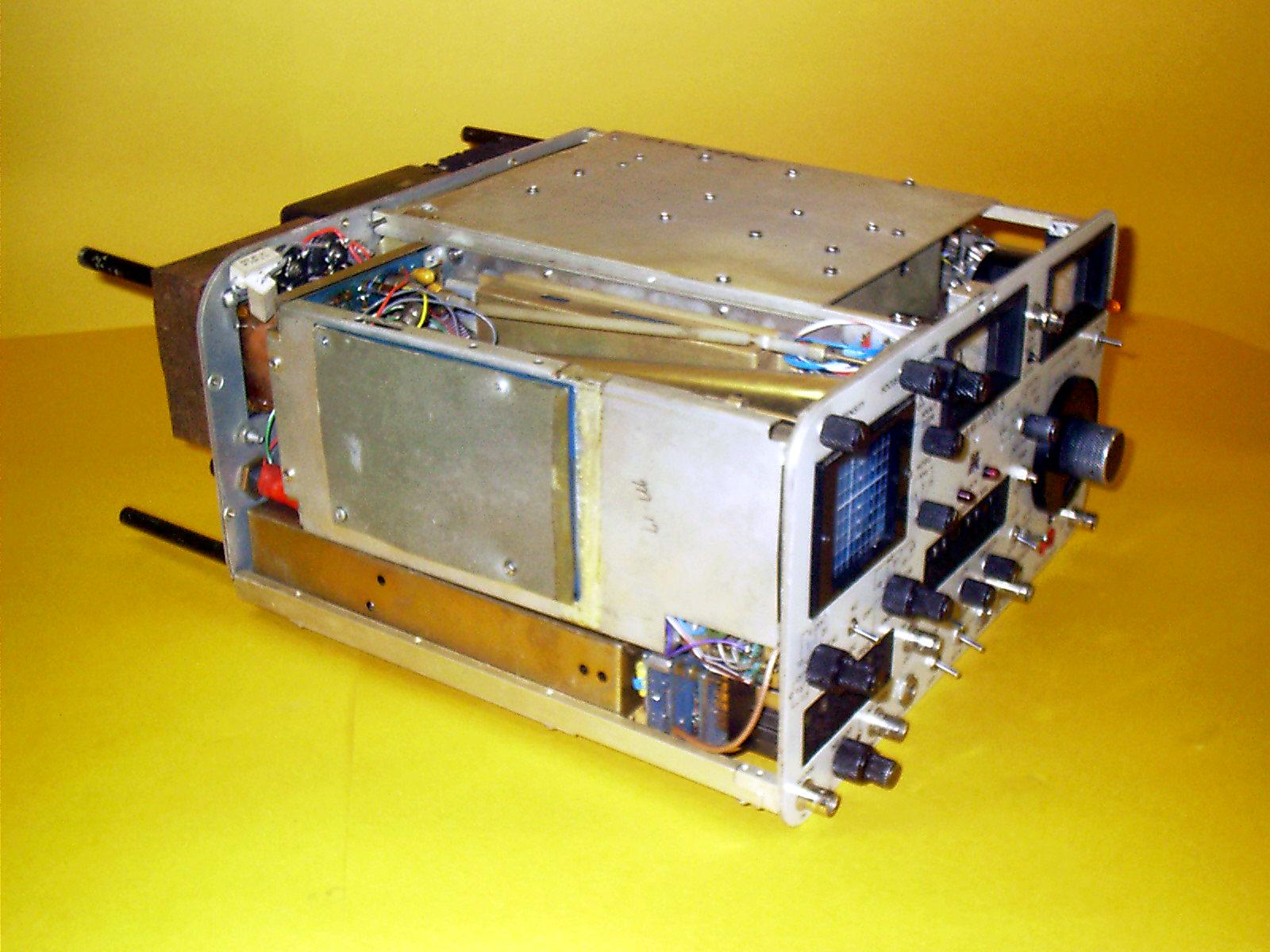
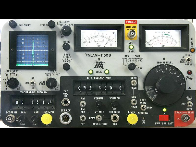
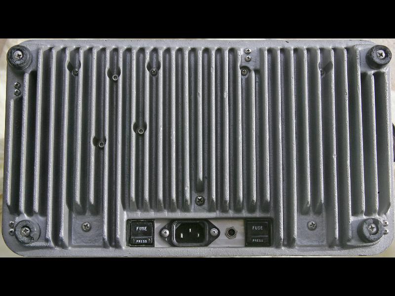
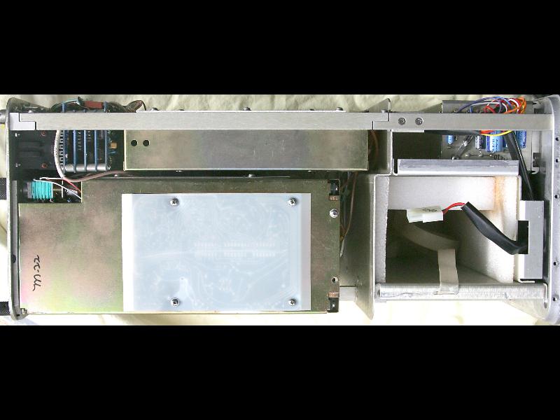
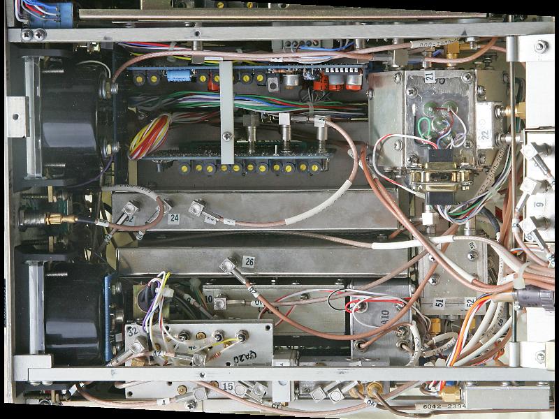
Photos courtesy of Tim Ahrens W5FN:
Front
Rear
Inside Left Side (scope side)
Inside Right Side (speaker side)
Inside Bottom
Internals: Top with Hinged Panel Closed
Underside of Hinged Panel
Internals: Hinged Panel Out of the Way
|
|
|
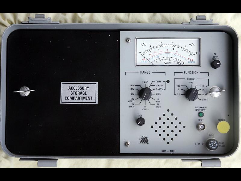
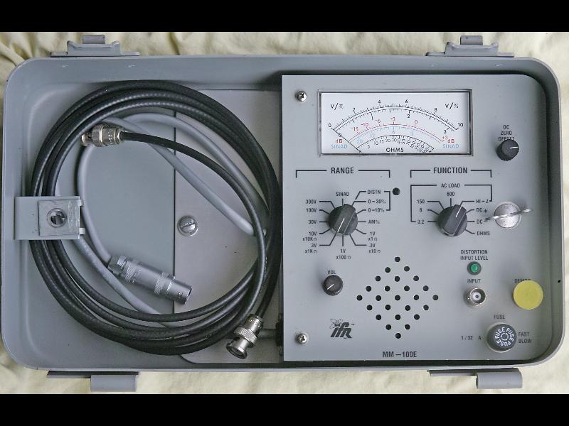
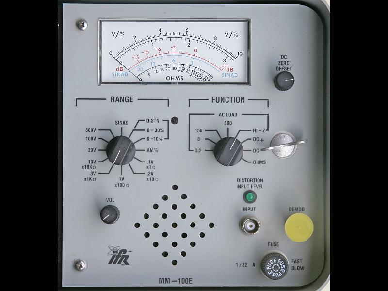
The MM-100E is the optional SINAD meter that mounts in the hinged cover.
Top (closed)
Top (open)
Controls
Side
Circuit Board
|
|
|
FM/AM-1100S/A Maintenance
Manual 49.1 MB PDF
|
|
|
FM/AM-1100S/A Operator's Manual 8.3
MB PDF
This is actually the military manual TM-11-6625-3016-10-1, Radio Test Set AN/GRM-114A,
(NSN 6625-01-144-4481)
|
|
|
Organizational Maintenance Manual
TM-11-6625-3016-20-1 5.5 MB PDF
|
|
|
FM/AM-1100S Calibration
Procedure 1.2 MB PDF
This is actually the military bulletin TB 9-6625-2059-35, dated 24-Sep-2004, for Test Set,
Radio AN/GRM-114A
|
| |
FM / AM-1200A/S documentation and articles:
|
|
|
The 1200 was the first variant, then the 1200 A (Analyzer), then the 1200 S that had the spectrum analyzer and tracking generator, then the 1200 Super. The 1200 SRA, was a receive-only surveillance unit made for the various Three Letter Agencies (TLAs), and does not
have any signal generator functions (but there is a BFO for CW and SSB monitoring). It cannot
be upgraded into a "real" 1200 A or 1200 S.
|
|
|
If you get a "checksum error" message on power-up take it as a warning
your CPU card coin cell is about to die!
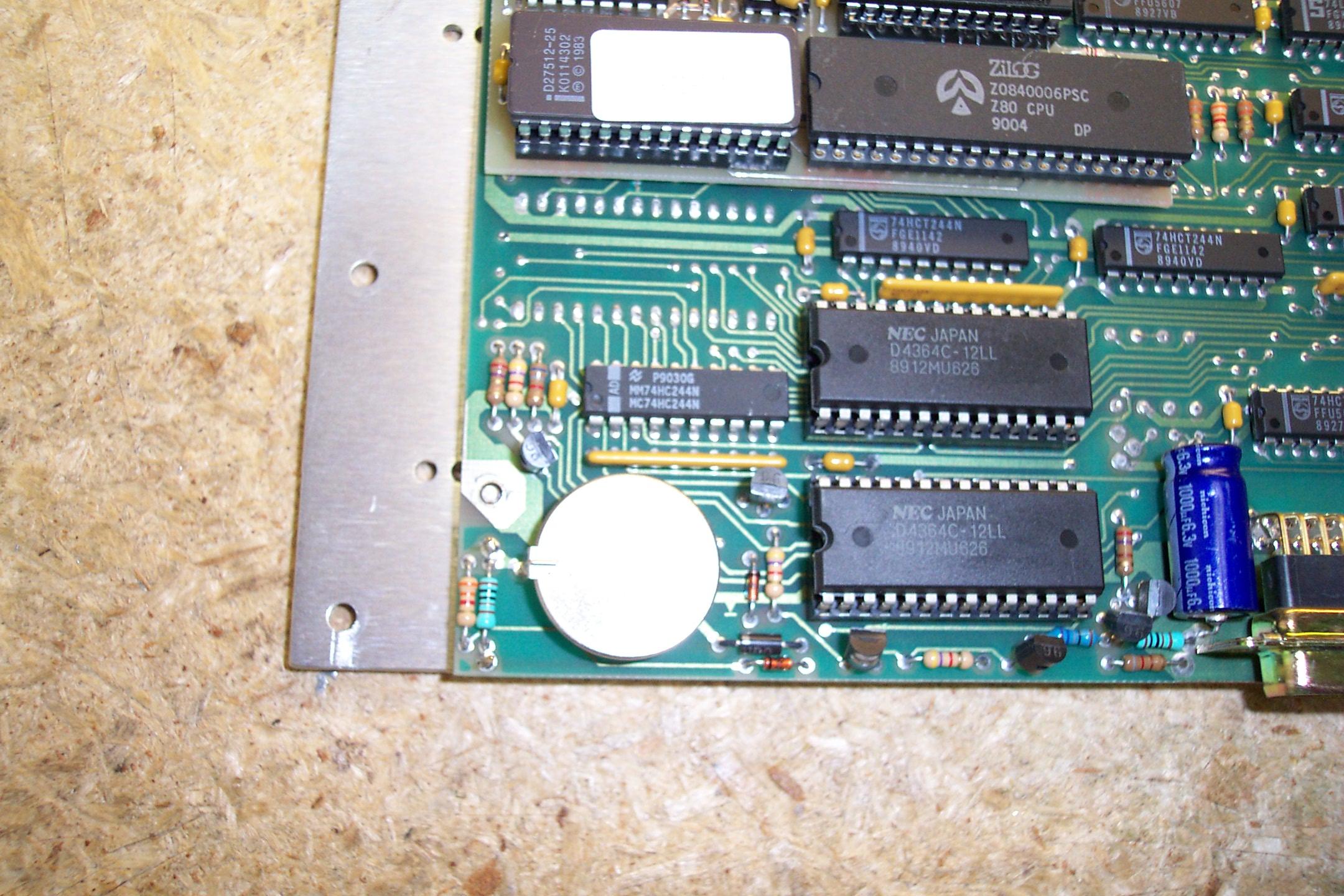
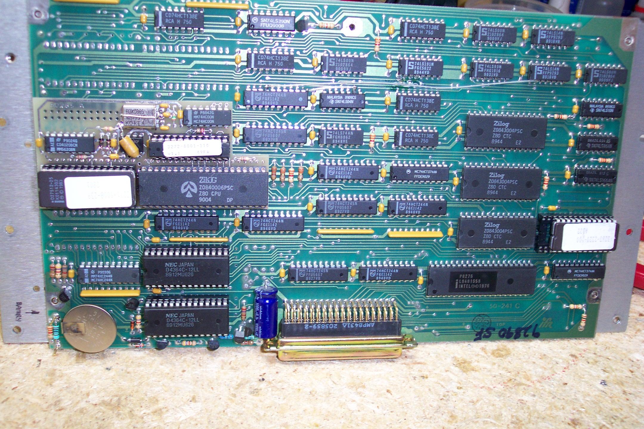
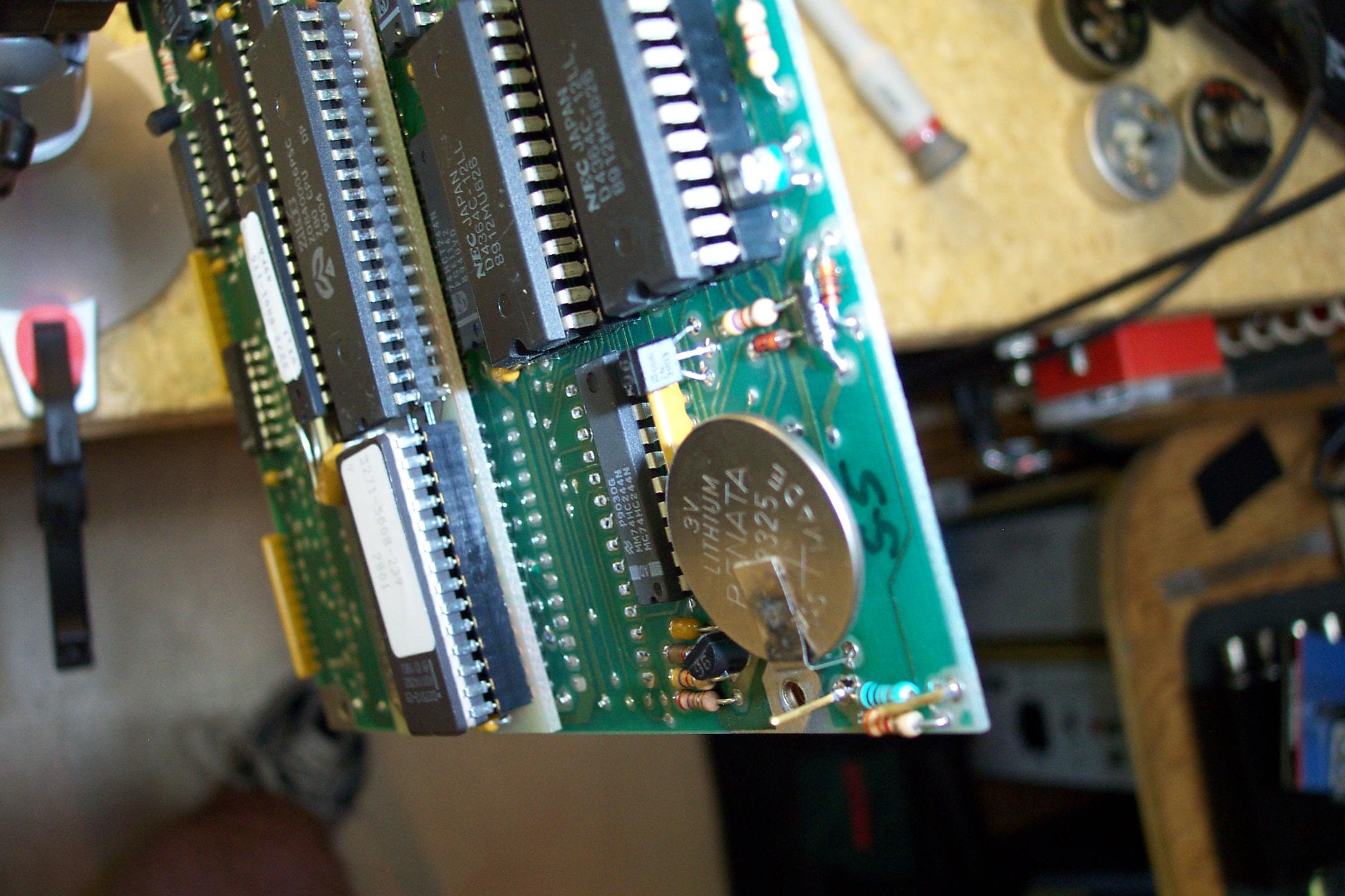
All of the 1200 product line units are over thirty years old. The CPU board has a
lithium coin cell battery on it, just like a PC motherboard from that era. The original
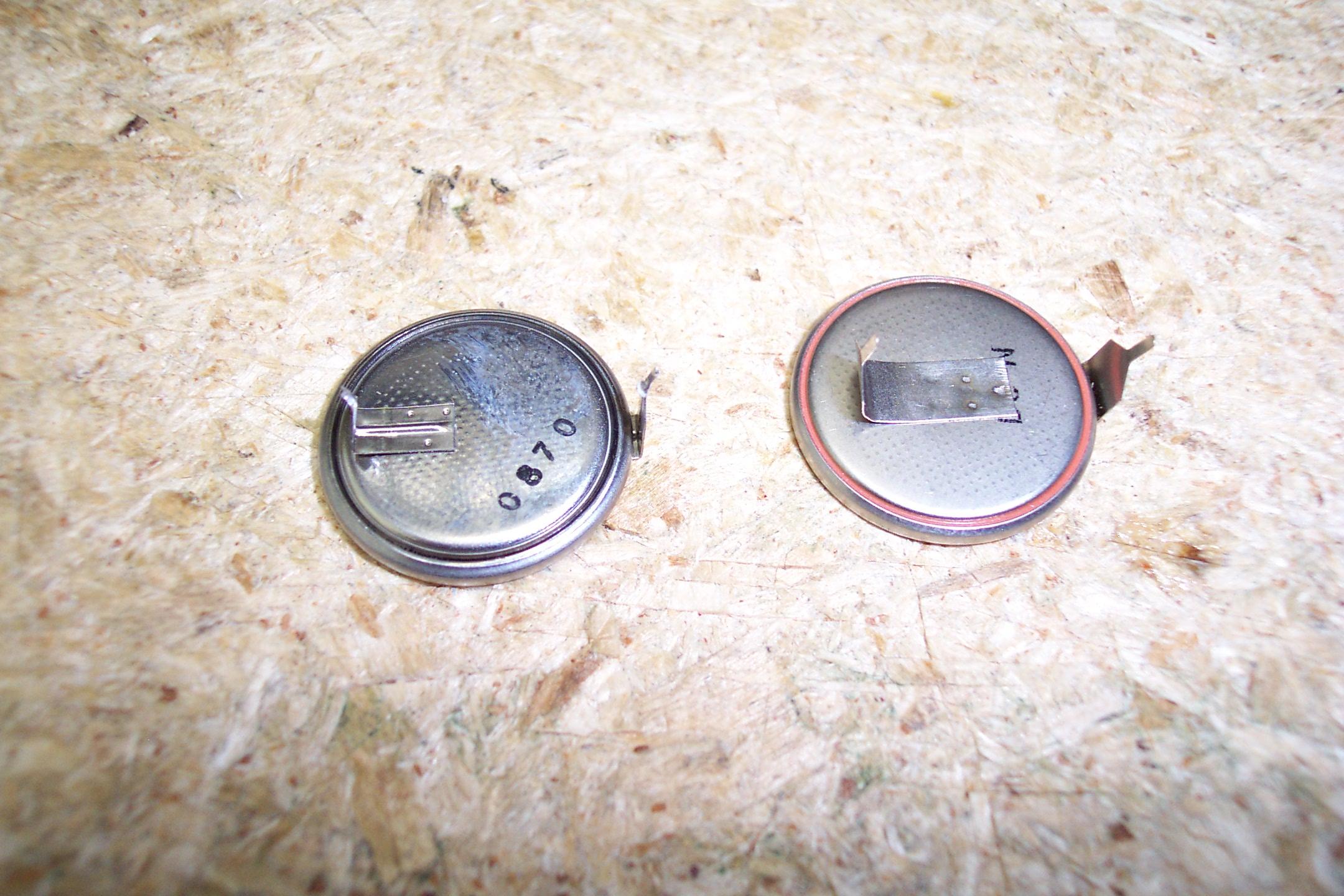
coin cell is a 3 volt BR2535P2B (160 mAH). The P2B indicated that
the coin cell has welded-on solder tabs... they are hard to find however at the time of
updating this paragraph (early 2026) they were available
here.
There isn't any vertical room for a battery holder on the face of the CPU card
so just replace it with another one. If you want to go with a battery holder you might be able
to fit one between the back of the CPU card and the adjacent card and use a pair of wires
to connect the holder to the CPU card.
The prefix (CR or BR) on a coin cell battery code indicates:
| Chemistry: | CR: Lithium Manganese Dioxide (LiMnO2). | BR: Lithium Carbon Monofluoride (Li-CF).
|
| Shelf Life: | Up to 10 years. | Up to 15 years. |
| Discharge Curve: | Gradual decline over time. | Flat voltage until sudden drop. |
| Current / Power: | Higher initial voltage and pulse current. | Lower pulse current, ultra-low self-discharge. |
| Temperature Range: | Standard consumer range. | Wider/higher extreme tolerance. |
The 4 digits tell you the physical size of the battery.
For example, on a 2325 battery: 23 means the diameter is 23 mm and 25 is the thickness: 2.5 mm
(25 tenths of a mm or 2500µm).
|
|
|
|
The power supply in the IFR 1200 series are difficult to troubleshoot
and tends to fail and burn up the circuit board in the process (which is usually
not repairable). Another failure mode has the +5 volt section failing
and placing the raw +16 volts on the +5 volt output. When this
occurs it blows almost every digital IC in the entire service monitor and
these days many of those chips are pure unobtanium. That failure mode is
generally fatal to the entire service monitor.
The power supply has multiple outputs: +12 volts, -12 volts,
+5 volts and +40 volts. The design of the original power supply
has interactions between the sections, if the +12 volt section drifts
the +40 volt and -12 volts sections drift with it. And the
design requires a mimimum load, so powering up a good supply with
zero load will give you weird readings and you will think it's bad.
Jay Hennigan WB6RDV had his IFR power supply fail and burn up
the circuit board in the process. He designed a drop-in replacement
that works perfectly in the IFR 1200, 1200A, 1200S,
and 1200 Super-S service monitors. His revision "D"
is compatible with both the early and late variants of the supply. Jay's
replacement is simple to build, you just solder the components to the
board, install it and it works. It uses a custom circuit board that holds
three packaged single-voltage Meanwell DC-DC converters and a few
support components. The Meanwell modules continue to work
down to around 11 volts when on external DC (yes, the IFR
has an external 12 volt DC input) or the internal battery
operation (if it is installed).
Once you have the PC board all of the parts are available from
Mouser or Digikey, and Jay has pre-configured parts ordering lists
on file at both companies.
You can send his Gerber files to any PCB house (JLCPCB.COM is
an excellent inexpensive source) and they can make you a board or
multiple boards. Jay's project is fully documented in the "readme.txt" file
that is included in
his ZIP file.
It contains everything you will need: the Gerber files, the Bill Of
Materials files, the KiCad board design files (should you want to
modify the design) and a schematic PDF file.
Stay away from the converters you find on AliExpress. Those run
really hot and the DC output is not as clean.
There is
a YouTube video
of the version "C" of this supply. (opens in a new browser window)
Jay took care in the design to avoid any RF generation and the result has
zero noticeable birdies.
|
|
|
The original IFR1200A cannot be upgraded to a 1220S (with tracking generator, etc)
and they have the infamous blue PC boards and are a real PITA to work on.
|
|
|
The IFR1200 product line was developed in the days of
wideband = 30 KHz channel spacing
and narrowband = 15 KHz channel
spacing. It is still quite usable on 5 KHz and 2.5 KHz signals.
|
|
|
FM/AM-1200S Electrolytic
Capacitors Replacement Guide 4.2 MB PDF by Alex Szuski KD6VPH
Don't bother doing the power supply section, just replace the supply board with the
WB6RDV-designed unit.
|
|
|
FM/AM-1200S Spare Parts
Guide 700 kB PDF by Alex Szuski KD6VPH
|
|
|
Photos from a Brochure: Photo 1
Photo 2
|
|
|
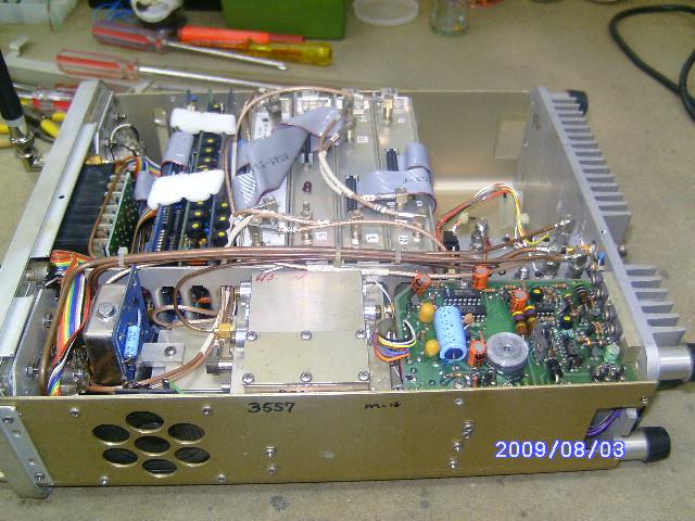
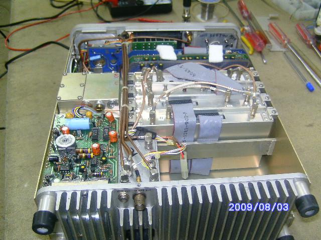
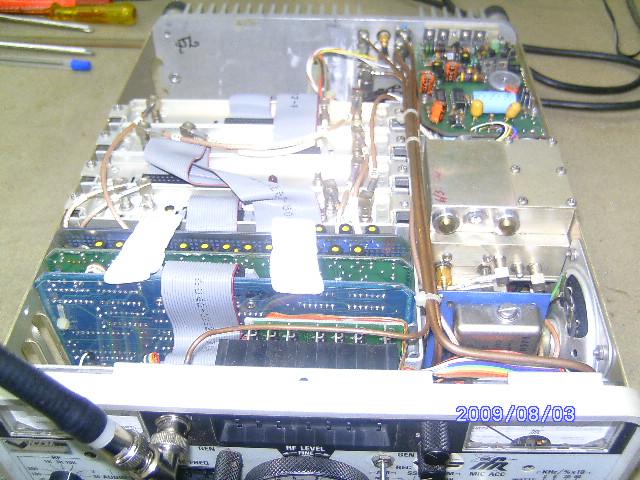
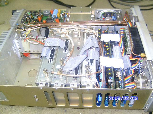
Interior and miscellaneous photos (courtesy of Bob Vaughan AF6RR):
Image 01
Image 02
Image 03
Image 04
Image 05
Image 06
Image 07
Image 08
Image 09
Image 10
Image 11
Image 12
Image 13
Image 14
Image 15
Image 16
Image 17
Image 18
Image 19
Image 20
Image 21
Image 22
Image 23
Image 24
Image 25
Image 26
Image 27
Image 28
Image 29
Image 30
|
|
|
FM/AM-1200A Data sheet 227 kB PDF
FM/AM-1200 Super S Data Sheet 145 kB PDF
"UUT" in the data sheet text = "Unit Under Test".
|
|
|
FM/AM-1200S/A Operations
Manual 7.3 MB PDF
This is a scan of a Revision 8 manual last updated on September 1 of 1991.
|
|
|
FM/AM-1200S/A Operations
Manual 5.7 MB PDF
A bit smaller and cleaner copy than the one above. It is the same manual.
Unfortunately neither is text serchable.
|
|
|
FM/AM-1200S/A Service
Manual 10.6 MB PDF
|
|
|
FM/AM-1200S/A Output and Tracking
Amplifier pages 2.1 MB PDF courtesy of Frank KA2FWC
This is the documentation for Option 5: the duplex generator 30dB / 100
milliwatt amplifier.
|
|
|
FM/AM-1200 Super S Operation
Manual 4.5 MB PDF
Includes the remote operation supplement.
|
|
|
T-1200SR Scanning Receiver Operation
Manual 700 kB PDF provided by Alex Szuski KD6VPH
|
|
|
A pointer to a youtube video
from 2014 on replacing the lithium coin cell on the CPU card By Alton "Buddy" Mclawhorn KC4UMO
|
|
|
Two IFR1200 problems and their solutions by Clint KA7OEI
Clint ran into a pair of broken IFR1200s and fixed both of them: one had the display showing nothing but "@" signs, and the other had a non-linear deviation meter.
|
|
|
Does anybody have any other manuals available for the 1200, military or otherwise?
One manual we'd really like to have is the FM/AM-1200 Super S Service Manual.
|

|
Page 1 of the IFR-1200 Operation Manual (High Definition)
58.86 MB PDF provided by Paul Andreasen, K1JAN and Don Clark for the IFR Monitors
group at IO.
|
|
|
Pages 2 to 184 of the IFR-1200 Operation Manual (High Definition)
487.90 MB PDF provided by Paul Andreasen, K1JAN and Don Clark for the IFR Monitors
group at IO.
|
|
|
Pages 185 to 224 of the IFR-1200 Operation Manual (High Definition)
185.40 MB PDF provided by Paul Andreasen, K1JAN and Don Clark for the IFR Monitors
group at IO.
|
|
|
Pages 225 to 265 of the IFR-1200 Operation Manual (High Definition)
86.44 MB PDF provided by Paul Andreasen, K1JAN and Don Clark for the IFR Monitors
group at IO.
|
|
|
IFR-1200 Maintenance Manual (High Definition)
818.52 MB PDF provided by Paul Andreasen, K1JAN and Don Clark for the IFR Monitors
group at IO.
|
|
|
IFR-1200 Operating Manual (High Definition)
88.25 MB PDF provided by Paul Andreasen, K1JAN and Don Clark for the IFR Monitors
group at IO.
|
| |
FM / AM-1500A/S documentation and articles:
|
|
|
Exterior photos (supplied by Andy WD4KDN):
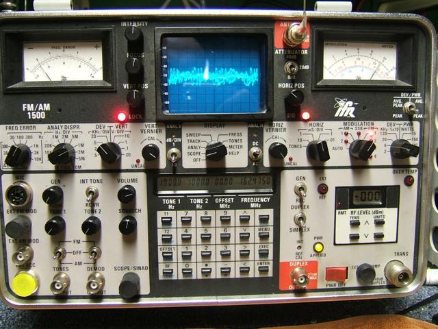
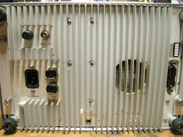
Photo 1
Photo 2
|
|
|
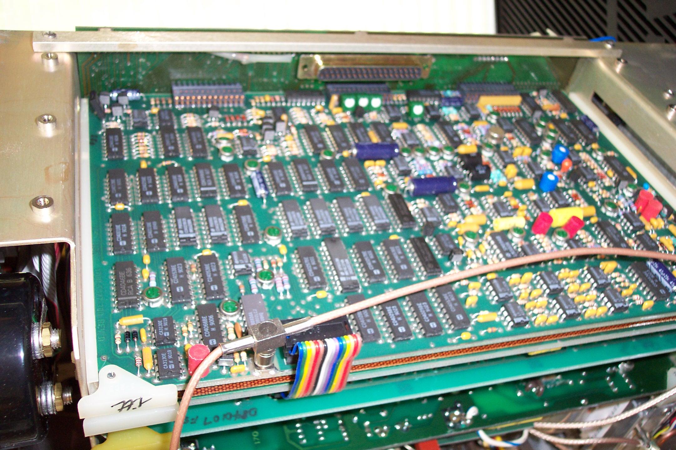
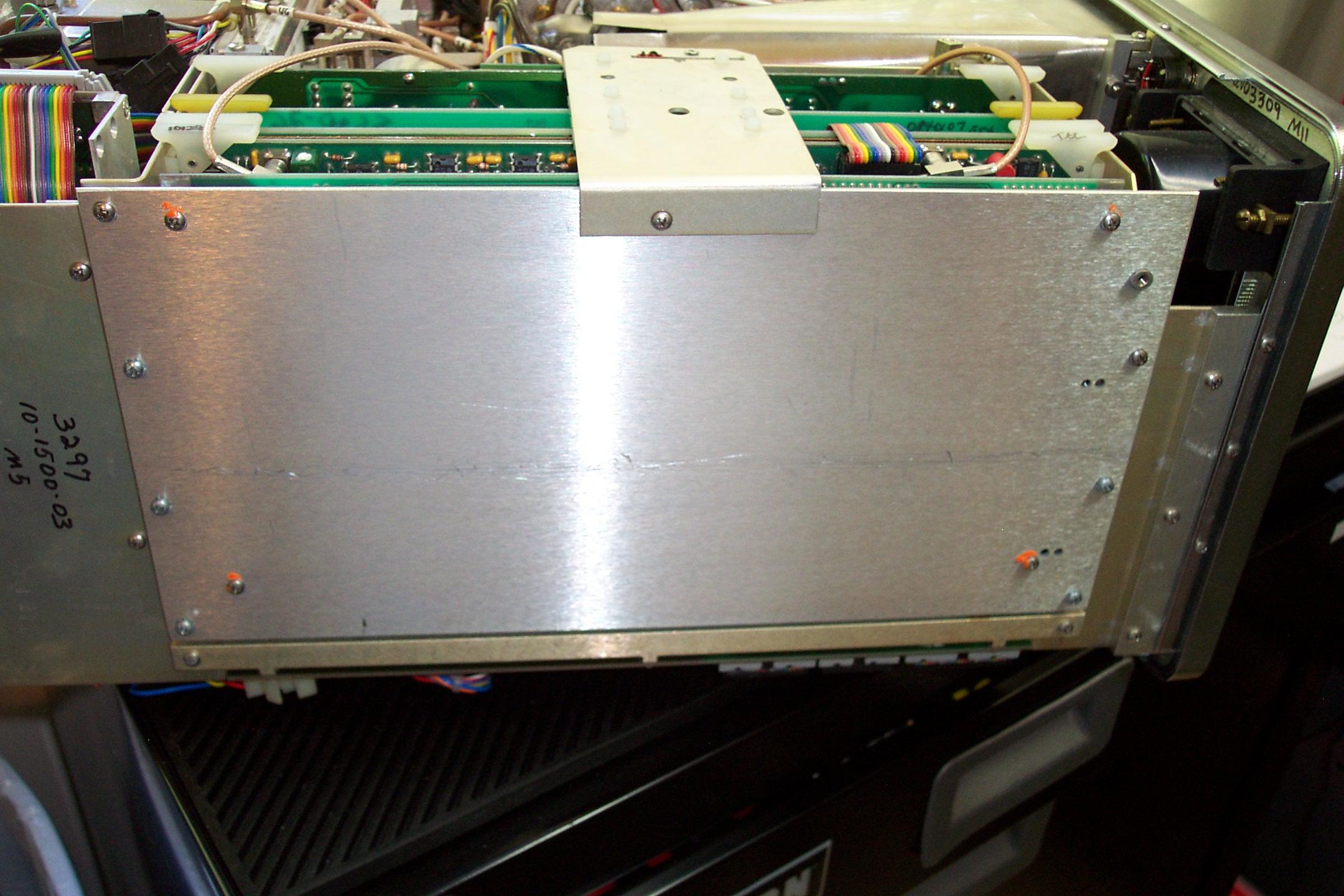
Interior and miscellaneous photos:
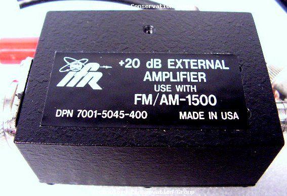
20dB Amplifier
New and Old Batteries
Battery Removed from PCB
Battery Installed on PCB
CPU and Memory PCB
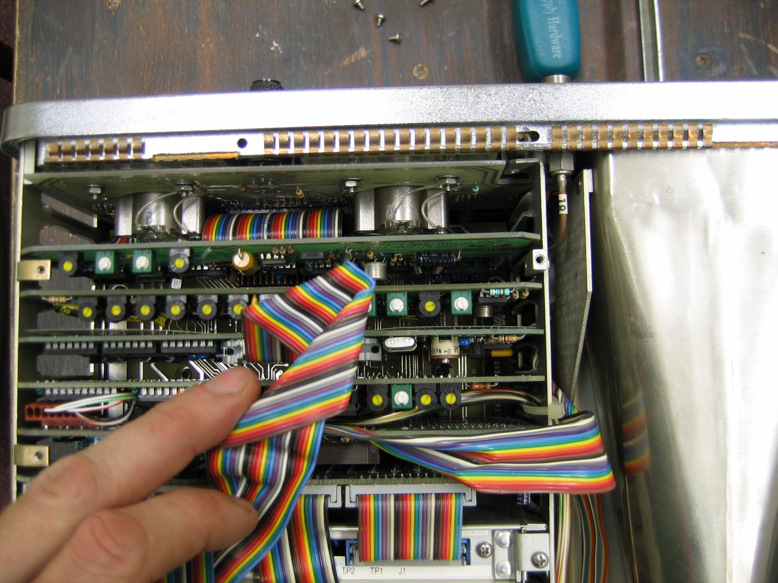
Inside the Front Panel
Interior (top) View
Interior (bottom) View
Motherboard Support Bracket
New Battery Installed
Next Card Behind CPU Circuit Board
Side Shield
|
|
|
When the coin cell in the 1500 dies you will get a "N.V. RAM Checksum Error" message.
Look in the 1200 section above for the pointer to the video on changing the coin cell in that model.
You really want to install a solder-in battery holder for a snap-in CR2032 coin cell.
A suitable and readily available one is a Keystone part 1066. The Digikey part number is 36-1066-ND or Mouser 534-1066.
|
|
|
FM/AM-1500 Application Notes 5.5 MB PDF
Scanned from a 1986 publication but the theory is as applicable as it was over 20 years ago.
|
|
|
FM/AM-1500 Power Supply Replacement
using commonly available power supplies. 2.36 MB PDF
By John Kuivinen, WB6IQS Vista, CA.
|
|
|
Another version of the IFR-1500 Application Notes...
IFR produced a spiral-bound book that was packed with each unit.
Joe Szczech K1IKE was kind enough to scan his, page by page.
Part 1 Cover and pages
1-9 2.3 MB PDF
Part 2 Pages 10-19 2.6
MB PDF
Part 3 Pages 20-29 2.8
MB PDF
Part 4 Pages 30-39 2.7
MB PDF
Part 5 Pages 40-55 4.3
MB PDF
Full IFR-1500 spiral book 4.9 MB PDF
straightened out and combined sections by Eric WB6FLY.
|
|
|
FM/AM-1500 Service Monitor Maintenance Manual
16.3 MB PDF
|
|
|
FM/AM-1500 Service Monitor Complete
Maintenance Manual 8 MB PDF
This manual, unlike the one above, contains revisions, schematics, and even test
fixtures and accessories. Considering the size and what's in it, this is a much
better deal.
|
|
|
FM/AM-1500 Service Monitor Complete
Maintenance Manual 45 MB PDF Donated by Robin K4IDC
Robin took the above file and processed the text so this file is searchable, making it
easier to use and find things.
|
|
|
FM/AM-1500 Service Monitor Operator's Guide
10.6 MB PDF
|
|
|
FM/AM-1500 Service Monitor Operator's Guide
47 MB PDF Donated by Robin K4IDC
Robin took the above file and processed the text so this file is searchable, making it easier
to use and find things.
|
| |
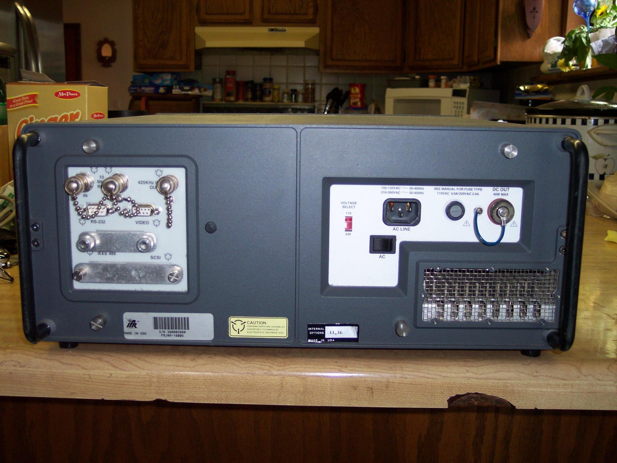
FM / AM-1600 / TS-4317 documentation and articles:
|
|
|
The IFR 1600 is also known as the TS-4317. That model has a known problem with the small electrolytics on the audio PA module.
When (not "if") they leak the electrolyte that was used inside them will corrode the PC board traces. Don't wait! Change them!
|
|
|
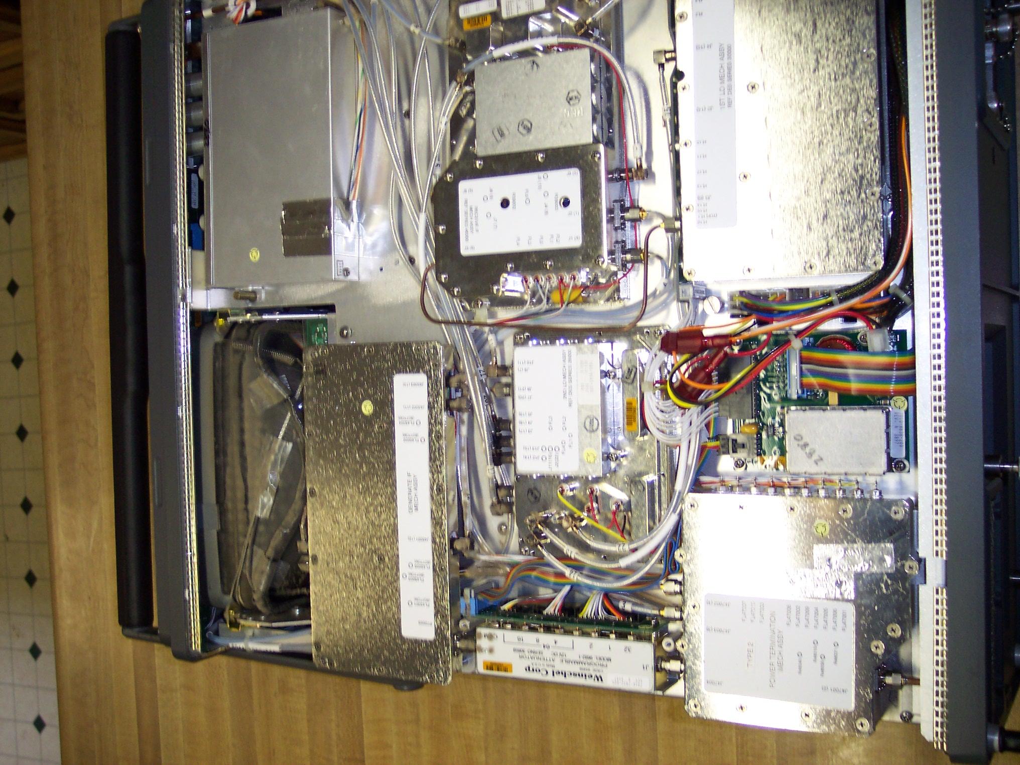
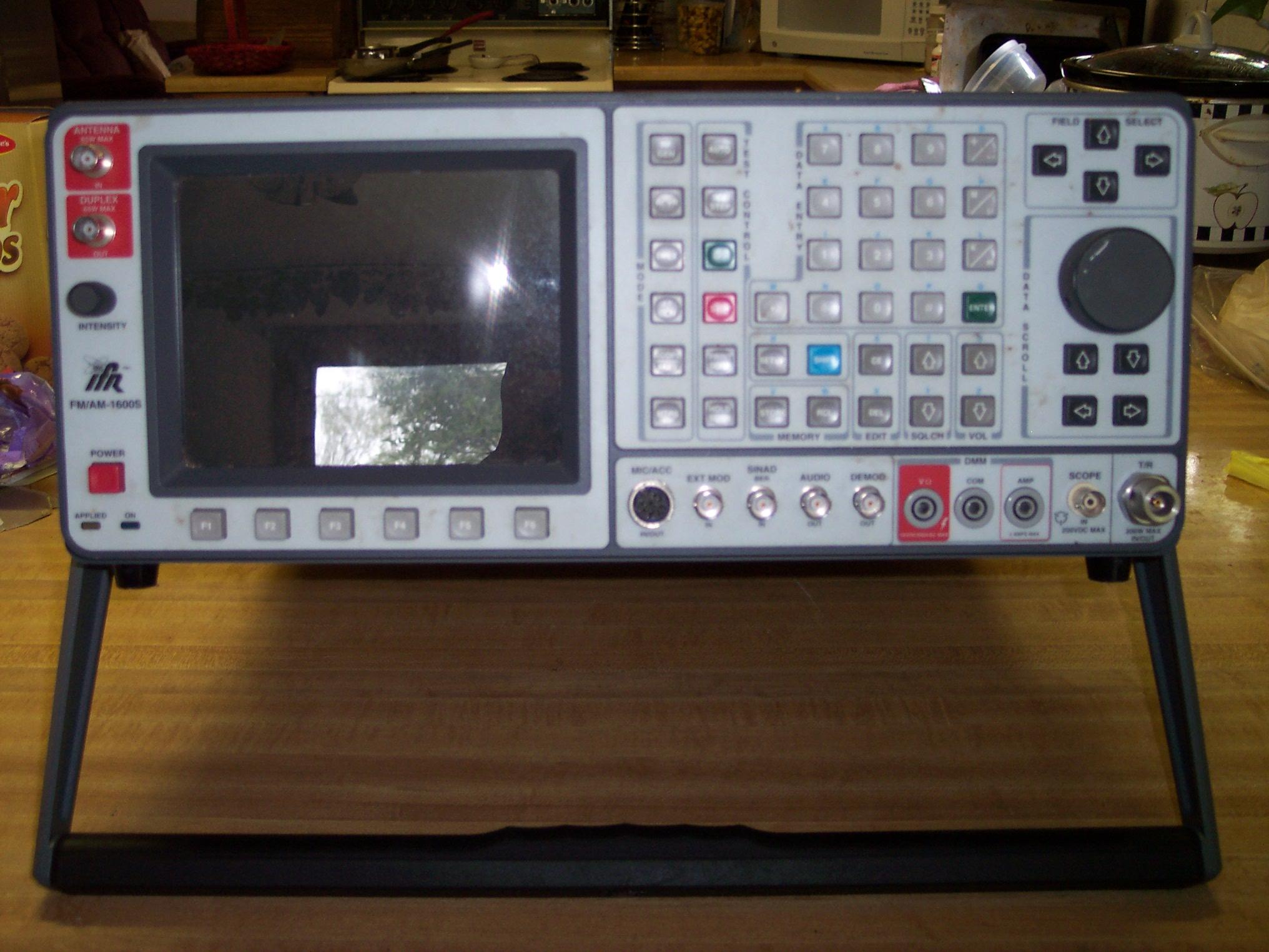
Photos courtesy of Joe Burkleo WA7JAW:
Back
Bottom
Front on Stand
Front Left
Front Right
Front
Top (angled)
Top (down)
|
|
|
FM/AM-1600S Operator's Manual Ver
1.10 13.2 MB PDF
|
|
|
FM/AM-1600S Operator's Manual Ver
2.00 13.8 MB PDF
|
|
|
FM/AM-1600S Operator's Manual Ver
4.00 25.3 MB PDF
|
|
|
FM/AM-1600S Maintenance Manual 16.4 MB
PDF scanned by Sam Reaves W3OHM
|
|
|
FM/AM-1600S Calibration Manual 8 MB
PDF scanned by Sam Reaves W3OHM
This is actually the military TS-4317-2 Radio Test Set version.
|
|
|
FM/AM-1600S and FM/AM-1600CSA TMAC
Manual 25 MB PDF
CSA is Cellular System Analyzer option. TMAC is the Test MACro (programming) language.
|
|
|
FM/AM-1600 General Support Maintenance
Manual 3.1 MB PDF donated by Sam Reaves W3OHM
This is actually the military TS-4317 AN/GRM-114B Radio Test Set version. Covers both the
LCD and CRT models.
|
|
|
FM/AM-1600 Operator's and Unit Maintenance
Manual 3.1 MB PDF donated by Sam Reaves W3OHM
This is actually the military TS-4317 AN/GRM-114B Radio Test Set version. Covers both the
LCD and CRT models.
|
| |
IFR 1900 documentation and articles:
|
|
|
1900 Operator's Manual 21 MB PDF
|
|
|
1900 CSA Option Operator's
Manual 6 MB PDF
CSA is Cellular System Analyzer.
|
|
|
1900 CSA TMAC User's Manual Vol
1 13 MB PDF
CSA is Cellular System Analyzer. TMAC is the Test MACro (programming) language.
|
|
|
1900 CSA TMAC User's Manual Vol
2 29 MB PDF
|
| |
IFR A-7550 documentation and articles:
|
|
|
The IFR A7550 has a solder-in BR2535 or CR2325 coin cell (memory battery) on the Control Processor Board next to U12.
See the coin cell notes in the 1200 section above. You really want to install a solder-in battery holder for a snap-in CR2032 coin cell.
A suitable and readily available one is a Keystone part 1066. The Digikey part number is 36-1066-ND or Mouser 534-1066.
|
|
|
A-7550 Spectrum Analyzer Sales
Brochure 2.5 MB PDF provided by Alex Szuski KD6VPH
|
|
|
A-7550 Spectrum Analyzer Operation
Manual 4.5 MB PDF
|
|
|
A-7550 Spectrum
Analyzer Operation Manual Supplement 02 1.2 MB PDF provided by Alex Szuski KD6VPH
|
|
|
A-7550 Spectrum Analyzer
Service Manual 11.5 MB PDF
|
|
|
A-7550 Spectrum Analyzer CRT
Board Capacitor Replacement Guide 923 kB PDF provided by Alex Szuski KD6VPH
|
|
|
A-7550 Spectrum Analyzer
Power Supply Capacitor Replacement Guide 901 kB PDF provided by Alex Szuski KD6VPH
|
|
|
A-7550 Spectrum Analyzer Option
10 Marketing Memo 244 kB PDF provided by Alex Szuski KD6VPH
|
|
|
A-7550 Spectrum Analyzer Spare Parts
Guide 429 kB PDF provided by Alex Szuski KD6VPH
|
|
|
A-7550 Spectrum Analyzer
Illustrated Parts Catalog 90 MB PDF provided by Alex Szuski KD6VPH
|
|
|
A-7550 Spectrum Analyzer Price List November
1, 1985 302 kB PDF provided by Alex Szuski KD6VPH
|
| |
COM-120 documentation and articles:
|
|
|
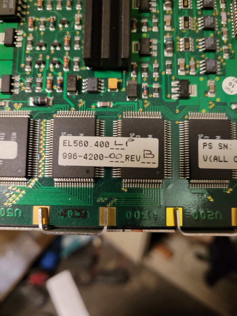
The COM-120A uses a no-longer-available Planar Systems, Inc. EL560.400 orange-on-black Electro-Luminescent display module.
It is a 6.9 inch diagonal 560×400 pixel device and the official data sheet is here.
If anyone has repair information or a source for them, please send it to the page maintainer.
Once the display module fails (and you are sure it's not the DC-DC converter) the only solution is to use an external VGA monitor - if you can find the VGA adapter card for the COM-120!
|
|
|
COM120 Options List. courtesy of Kurt WB6SMC - 74kB PDF.
|
|
|
COM120 Timekeeper Option Restoration.
courtesy of Kurt WB6SMC - 235kB PDF.
|
|
|
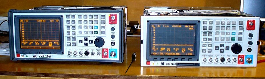
Click here for a photo of the COM-120A and COM-120B
courtesy of Tracy N4LGH.
|
|
|
Click here for a photo of the rear panel of a
COM-120B courtesy of Tracy N4LGH.
|
|
|
Click here for a 19.3 MB Zip file of COM-120A photos.
27 high-resolution pictures of a disassembled COM-120A, courtesy of Tracy N4LGH.
|
|
|
Click here for a 11.6 MB Zip file of COM-120B photos.
16 high-resolution pictures of a disassembled COM-120B, courtesy of Tracy N4LGH.
|
|
|
COM-120B Operation Manual 33 MB PDF
|
|
|
COM-120B Calibration Manual 2.5 MB PDF
|
|
|
COM-120B Schematic Diagrams 9.7 MB PDF
COM-120B Schematic Diagrams v2.0 26 MB PDF
The second download - all 202 pages - is a MUCH better scan! v2.0 is courtesy of Gerald Molenkamp VK3GM
|
|
|
COM-120B Application Manual 2 MB PDF
|
|
|
COM-120B Data Sheet 212 kB PDF
|
|
|
COM-120B Training Powerpoint file
3.1 MB PPT
|
|
|
COM-120C Operation's Manual 2.5 MB PDF
|
|
|
COM-120C Maintenance Manual
Supplement 2.7 MB PDF
Supplement for the COM-120B Maintenance Manual that covers the COM-120C.
|
|
|
According to a local two-way radio tech, if your COM-120 fails its self-test in the
'Dev. Modulation' or 'Dist. Meter' area you will need to change all of the electrolytic
capacitors in the baseband tray. IFR had a bad batch of them.
|
This page initially created 30-March-2009 by splitting all of the IFR information away
from the Other Manufacturers page.