Up two levels
Back to Home
Compiled and Maintained Mike Morris WA6ILQ.

|
Up one level Up two levels Back to Home |
Information and Modifications for the MSR2000 station Compiled and Maintained Mike Morris WA6ILQ. |
|
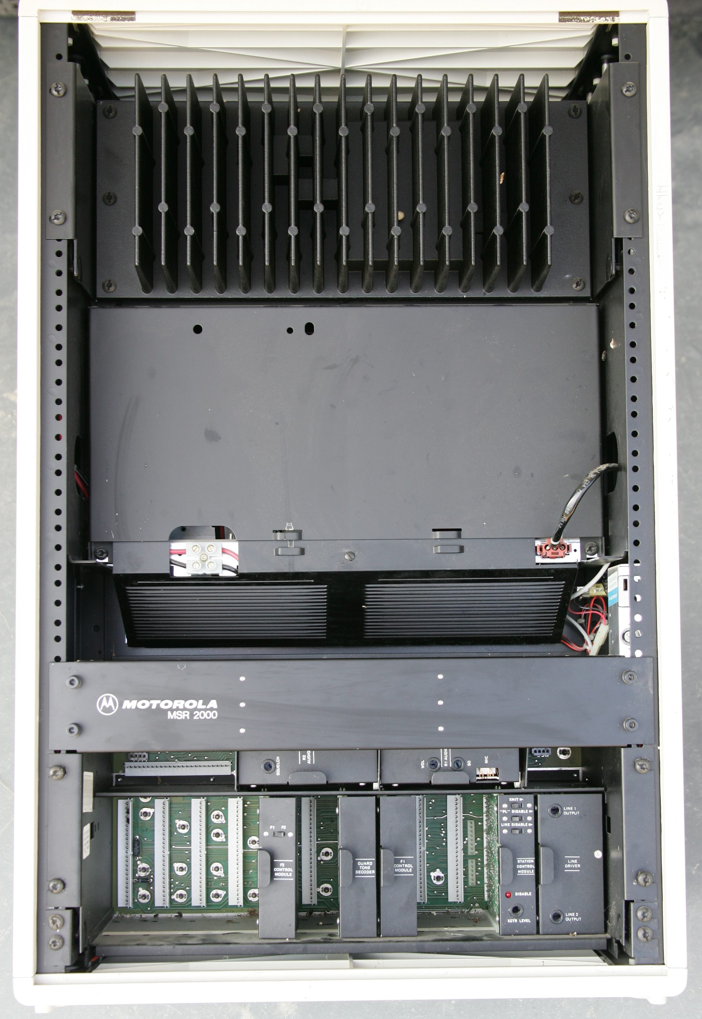
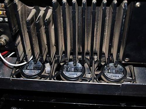
Photo 1: A dual receiver wireline controlled MSR2000 continuous duty station.
The exciter and receiver card(s) are behind the panel above the horizontal cards.
The empty horizontal slot at the top left is for the "coded squelch" card (either
PL or DPL).
The rightmost (double wide) vertical card is the line driver, the card to the left of it is
the station control card.
The three cards in the center are usually used only in tone controlled wireline systems.
Models with an in-cabinet duplexer are in a taller cabinet, with the duplexer at the bottom.
MSR indoor cabinets are 21 inches wide, 10 inches deep, and come in multiple heights.
The one in the photo above is 32 inches high.
Click on the image above for a larger image (576KB). Photos by Tim Ahrens W5FN
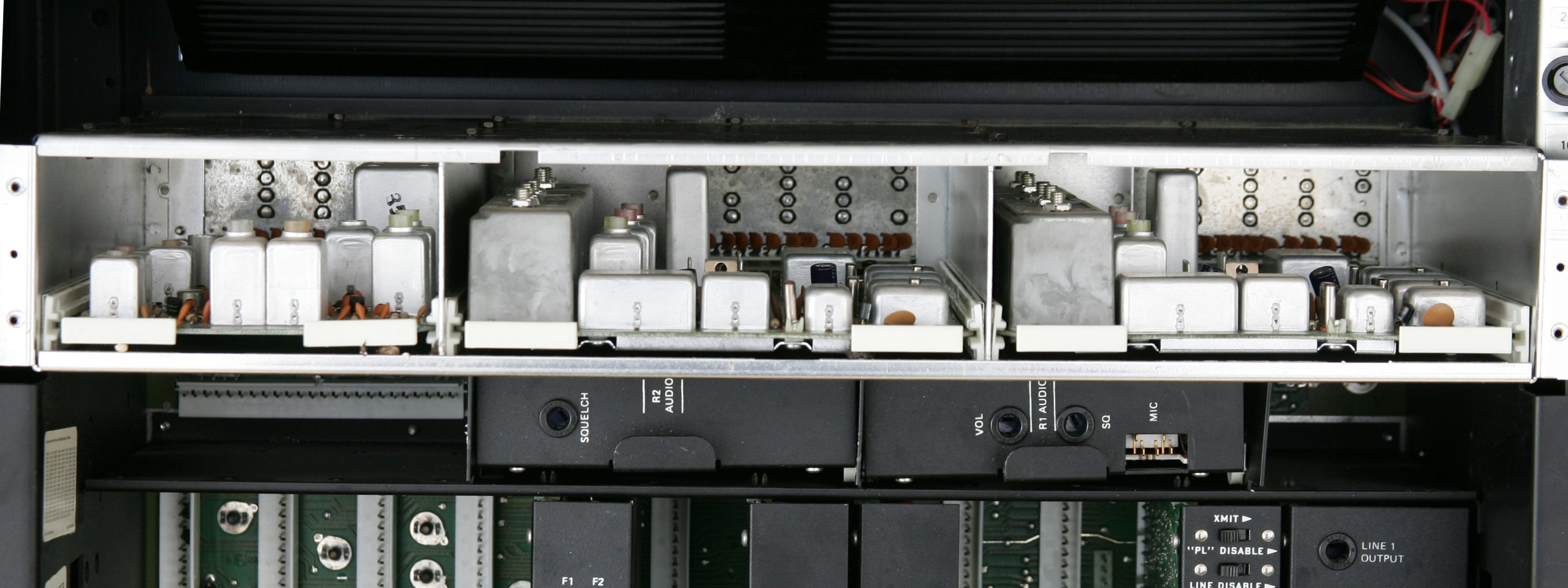
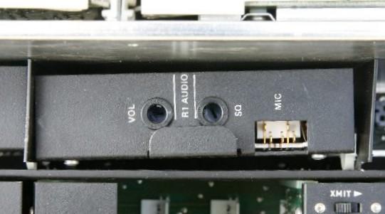
Photo 2: A view of the exciter and receiver card(s). From the left is the exciter, the
second receiver and the primary receiver.
Most MSRs do not have the second receiver, and would have an empty center horizontal slot.
Both a single receiver base station and a repeater station will usually be missing the connector
for the second receiver.
There are at least two different backplanes used - simplex, duplex, with the horizontal card
slots and without.
Click on the image above for a larger image (457KB). Photos by Tim Ahrens W5FN
Note: Any Motorola prices mentioned on this page (or on any page at this web site) should be taken only as a rough guideline. Motorola adjusts prices quarterly, and offers one set of prices to their dealers/service shops (the so called "NSO" Pricing ("National Service Organization")), another to "self-maintaining" fleet customers (i.e. those that have their own radio shops... cities, counties, police departments, fire departments, etc) and a third on their telephone order desk (i.e. retail sales). For these reasons readers should use the prices mentioned in an article only as a rough indication. We'd appreciate an emailed update if you discover a major price change.
The MSR2000 is a base or repeater station that was a follow-on to the MICOR line, and was available only in high band VHF and UHF. It is the last non-synthesized base station made, and is basically a second-generation MICOR station control shelf mated to separate receiver and exciter modules that are derived from the Mitrek mobile. The exciter drives a MICOR-derived PA deck.
The station shelf has a few upgrades (like the horizontal slots at the top, and a new, more reliable style of card-to-backplane connector). The control card cage is almost identical to a MICOR and most of the notes on the MICOR station control shelf are applicable. If you replace the card edge connectors that mate with the MICOR backplane with ones made for the MSR you can use several of the MICOR cards in the MSR card cage - BUT NOT ALL. Compare the function of each pin and the polarity of the signal before you go to the trouble of changing the connectors.
Both the receiver and exciter modules use a frequency-determining component called a Channel Element. This is a self-contained oscillator-tripler plug-in module, and there is one element for the receiver and a separate one for the exciter. The exciter element contains the modulator. When you move an MSR from one frequency to another it requires swapping the Channel Element for one on the new frequency, or changing the frequency of the Channel Element by replacing the internal crystal with a new crystal for the new frequency. This article is worth reading: Why should you really should spend $50 to re-crystal a channel element.
A list of the various channel elements used in the MSR station and the Mitrek mobile is here: Channel elements for the Mitrek and MSR2000.
As far as I can tell from the manuals, the model number structure on the USA-built
MSR2000s breaks down as:
| Sample model number: C74GSB-3106BTX Numbers in ( ) refer to notes below. | |||||
| C | 7 | 4 | G | S | B |
| Cabinet Type (1) |
Power Level |
Frequency Band (2) |
Duty Cycle (3) |
Configuration (4) | Supply Voltage (5) |
| B Base Station Cabinet |
5 40-70 watts |
3 VHF |
G Intermittent |
R Base Station (no duplex shield kit, has the base station backplane) |
A +12vDC (rare) |
| C Compact Cabinet |
6 70-90 watts |
4 UHF |
K Continuous |
S Repeater (has the duplex shield kit and duplex backplane) |
B 120vAC |
| N No Cabinet |
7 90-120 watts |
K 120v or 240vAC |
|||
| Sample model number: C74GSB-3106BTX Numbers in ( ) refer to notes below. | ||||||
| 3 | 1 | 0 | 6 | B | T | X |
| Squelch Type (6) |
Channel Deviation (7) |
Frequencies (8) | Control (9) | Hardware Version |
Configuration (10) | (?) (11) |
| 1 Carrier |
0 15 kHz |
0 Single Frequency |
3 Local Only |
A | A (?) |
X (?) |
| 3 PL |
1 5 kHz |
3 Two Frequency |
5 DC Wireline |
B | B Base |
|
| 6 DPL |
9 Four Frequency |
6 Tone Wireline |
C | D (?) |
||
| 7 (?) |
D | T Repeater |
||||
If anyone would like to contribute any information on how the model numbers for the Canadian-built units are different just let Mike WA6ILQ know.
Table Notes:
The
Model Tables, Option Tables and Specifications from the 6881061E50-C VHF manual
1.7 MB PDF file
From these tables you can fully decode the cabinet model number and figure out what your
station was originally shipped with. Note that the full manual PDF is available below.
Carrier Squelch, PL and DPL:
As said above, changing squelch types involves changing out the PL or DPL squelch card
(or adding one if you have a carrier squelch station) and rearranging some jumpers.
There are three different PL cards,and three different DPL cards.
In all cases the receiver audio path starts at the receiver slot, then goes to the R1 audio
card, then to the PL or DPL card, then back to the R1 audio card. Both the PL and
DPL cards have an on-board high pass / low cut audio filter that removes the PL
or DPL frequencies. If you have no audio in your surplus MSR2000 and an empty
PL / DPL card slot then you need to insert (add) the JU1 jumper on the R1 audio
card to bypass the missing audio filter on the missing PL or DPL card.
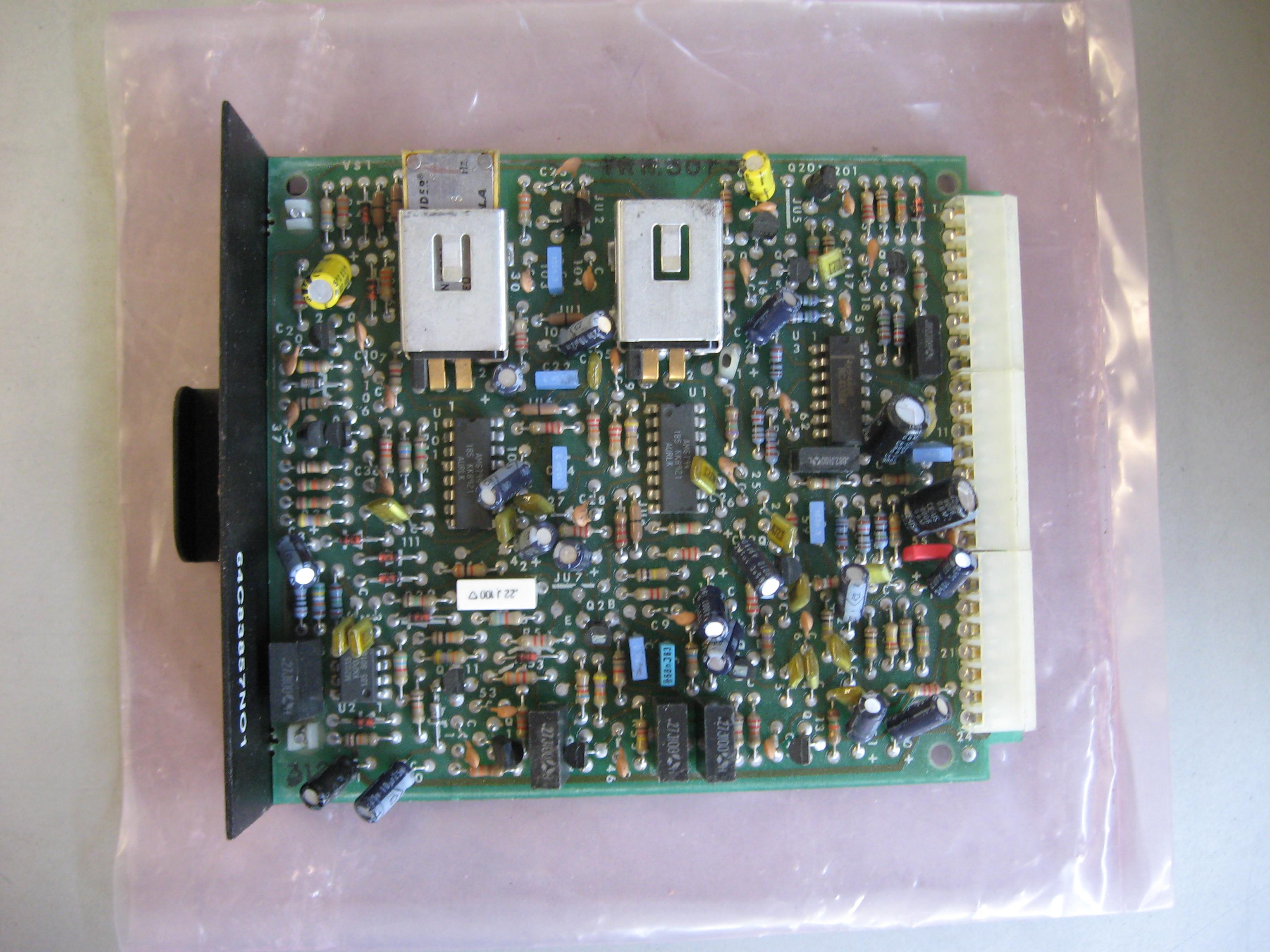
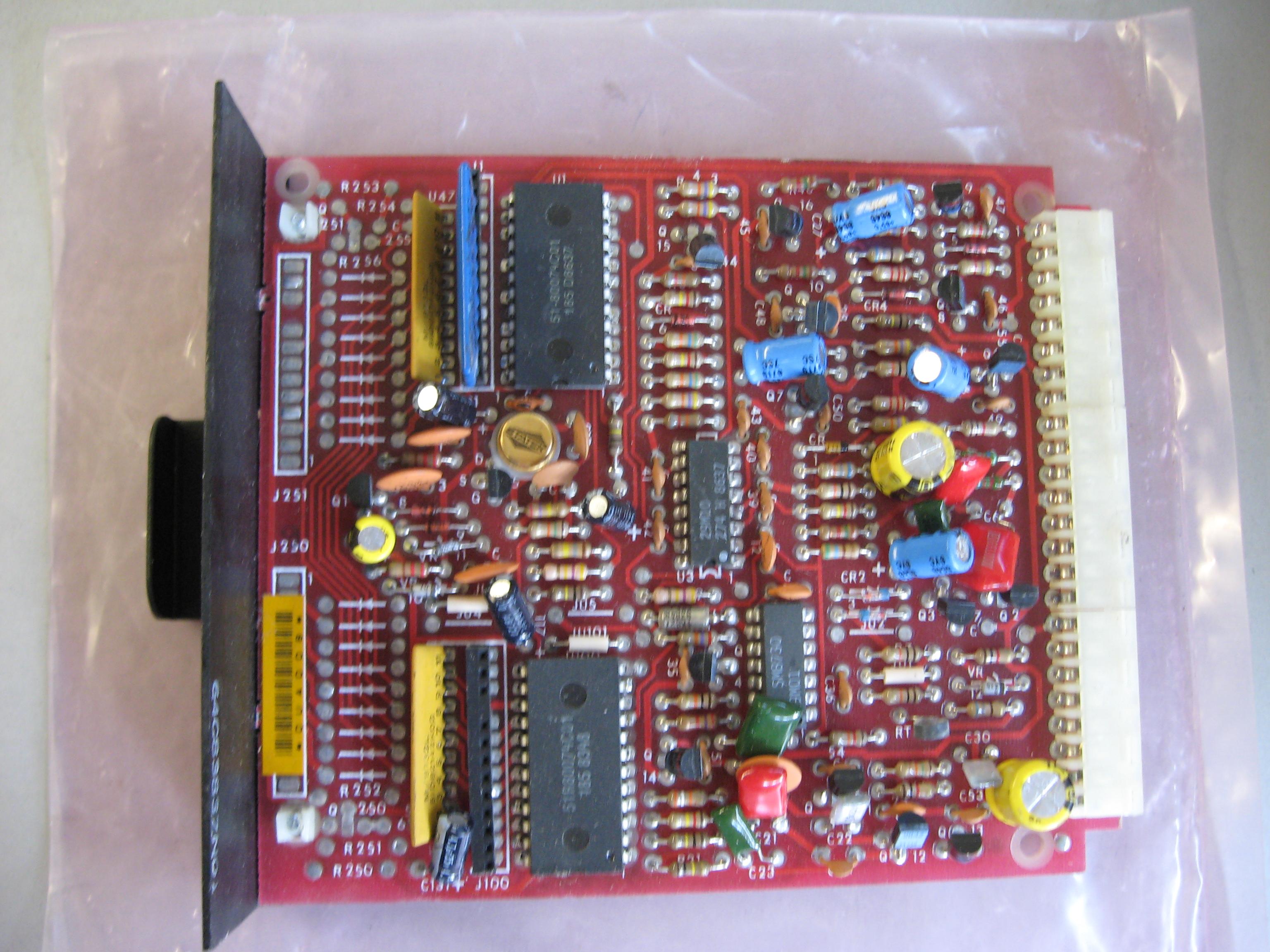
All three PL cards were built from the same bare PC board, the difference was the parts complement and the jumpers on the card. The TRN5074 and TRN5075 were intended for base stations where the TRN5073 (click for a photo) is the duplex PL board you need for repeater service as it supports simultaneous PL decode and encode. The documentation refers to the TRN5704 and TRN5705 as "simplex" PL boards (in this usage simplex means that the board can either encode during transmit or decode during receive, but not both at the same time). The TRN5074 is a single-reed card that forces you to use the same tone on receive and on transmit. The TRN5075 board (click for a photo) is a dual reed simplex board that can alternately do split tones (i.e. encode one tone and decode another tone).
Conversion of the TRN5074 or TRN5075 to a TRN5073 is straightforward. Print off the schematic, parts list and parts layout for the TRN5073 board, and the one for your TRN5074 or TRN5075. Acquire the parts. Suck out the solder from the holes, install the missing parts. Test and install.
We'd be happy to host a conversion article if anyone would like to shoot a set of photos as they convert a card.
As to the tone reeds themselves, the parts list for all three PL boards calls for a KLN6209A reed as the decode reed and a second KLN6209A as the encode reed. My own personal experience (hams tend to be experimenters) shows that a KLN6210A reed will work - and this implies that a TLN6824A will also work. The early MICOR mobile manuals specified a TLN6824A as the encode reed and the later MICOR mobile manual showed the KLN6210A reed. According to an engineer at Motorola in El Segundo California the KLN6210A and the TLN6824A are essentially the same reed, the TLN6824 is the older design with a metal case and the KLN6210 is the newer cost-reduced model with a plastic case. I've interchanged 6209s and 6210s out in the field and not noticed any difference. I've also used a leftover K-1000 reed from an old Com-Spec decoder and not noticed any difference.
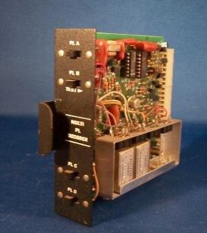
If the customer needed multiple tone PL decode or encode in their MSR station Moto
put a TRN53259A card in the otherwise empty tone burst decoder position (slot 11) on
the left side of the card cage. A matching multiple tone encode card went into
slot 12. These two cards use different reeds (TLN6824A or KLN6210A for the
encoder, TLN8381A in the decoder). A "Matrix" card went in a third slot and
allowed the tone remote system to control the encode and decode characteristics.
If you need multiple tone and can't find a real Moto card you can home-brew your own
with one or more TS-32s or TS-64s mounted on a card (a timeout timer card makes a
good candidate to be stripped and recycled in this way).
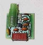
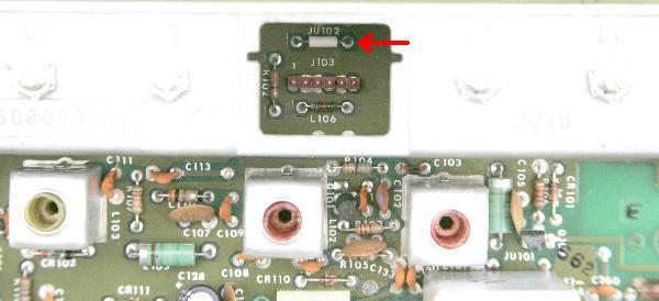
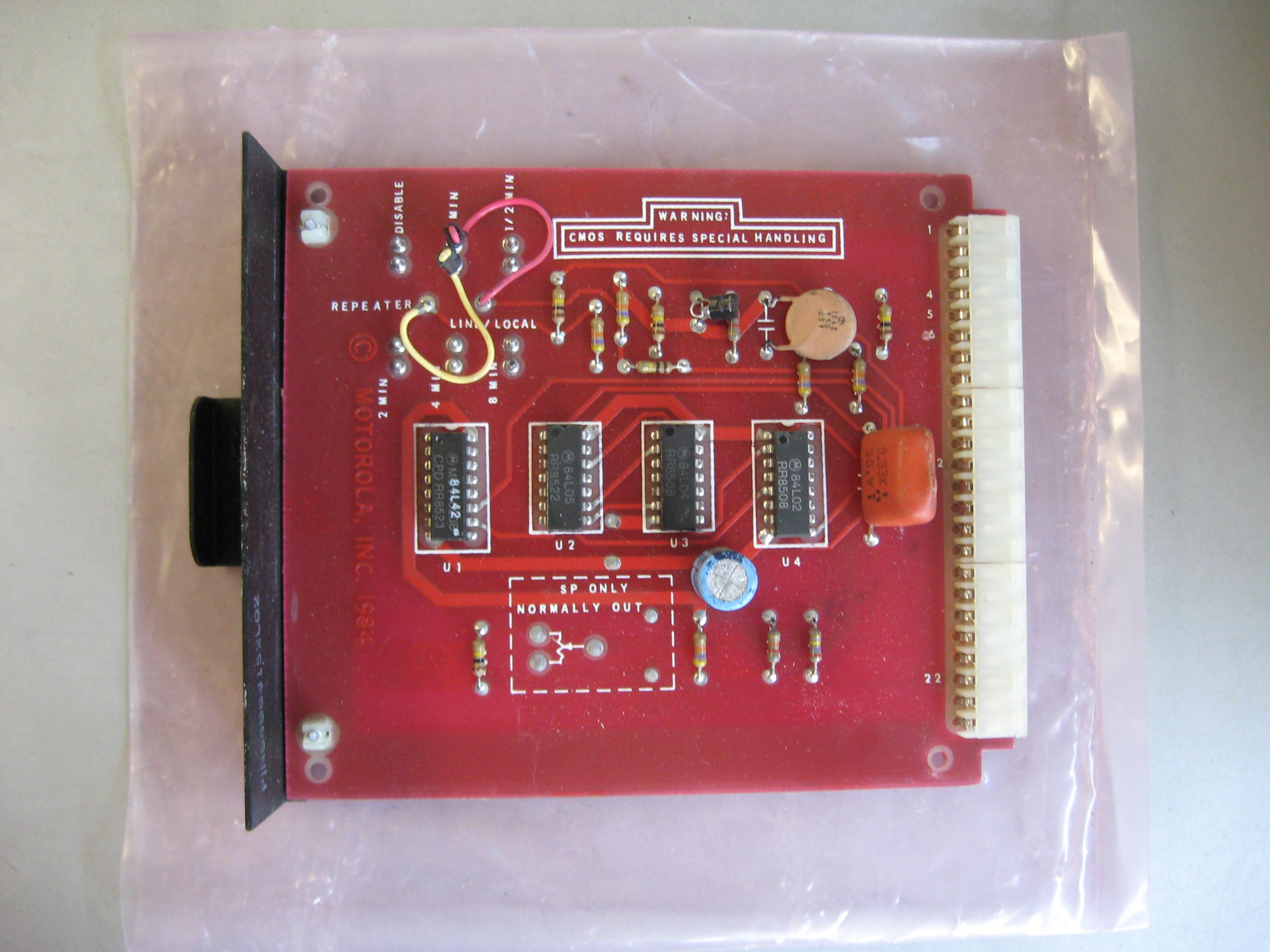
As to DPL, again there are three boards, all based on the same bare PC board. The TRN5076 is the duplex DPL board, the TRN5077 is the single code simplex DPL board and the TRN5078A is a simplex board that can do split codes. Here's a photo of a DPL board. The vertical blue bar that is next to the large chip at the top is a TRN6005 code plug. There is an article on this web site on how to make your own code plugs. The particular system that the DPL board in the photo came out of was DPL receive and carrier transmit, hence the lower code element socket (J100) in the photo is empty.
Again, we'd be happy to host a conversion article if anyone would like to shoot a set of photos as they convert a card.
If you have a second receiver in your station you will also have one of three second receiver control boards (the metal plate on the end of the card has the name "R2"). The TRN9690 module was for carrier squelch applications, the TRN9691 was for PL squelch applications and the TRN9692 was for DPL squelch applications. The TRN9690 and TRN9691 use the same circuit board and the TRN9690 board can have the missing parts added to make it a TRN9691. The TRN9692 DPL board uses a unique PCB. The information on all three R2 cards is in the "Audio and Squelch" section of the "Control and Audio" manual: 6881061E40.
Station Notes
| VHF Low Band (30-50 MHz) or Mid Band (66-88 MHz) |
|---|
| As far as I know, there never was a MSR2000 on low band (30-50 MHz), mid band (66-88 MHz), 800 or 900 MHz. I believe that if a customer needed one Moto sold them a MICOR station. |
| VHF High Band (132-174 MHz) Exciters | |||||||
|---|---|---|---|---|---|---|---|
| Model number (plus A or B suffix) (see note) |
Frequency MHz |
Filtering (see note) |
Mode | Module Connector |
Notes | ||
| TLD9231 | 132-150.8 | No | Simplex | Female | |||
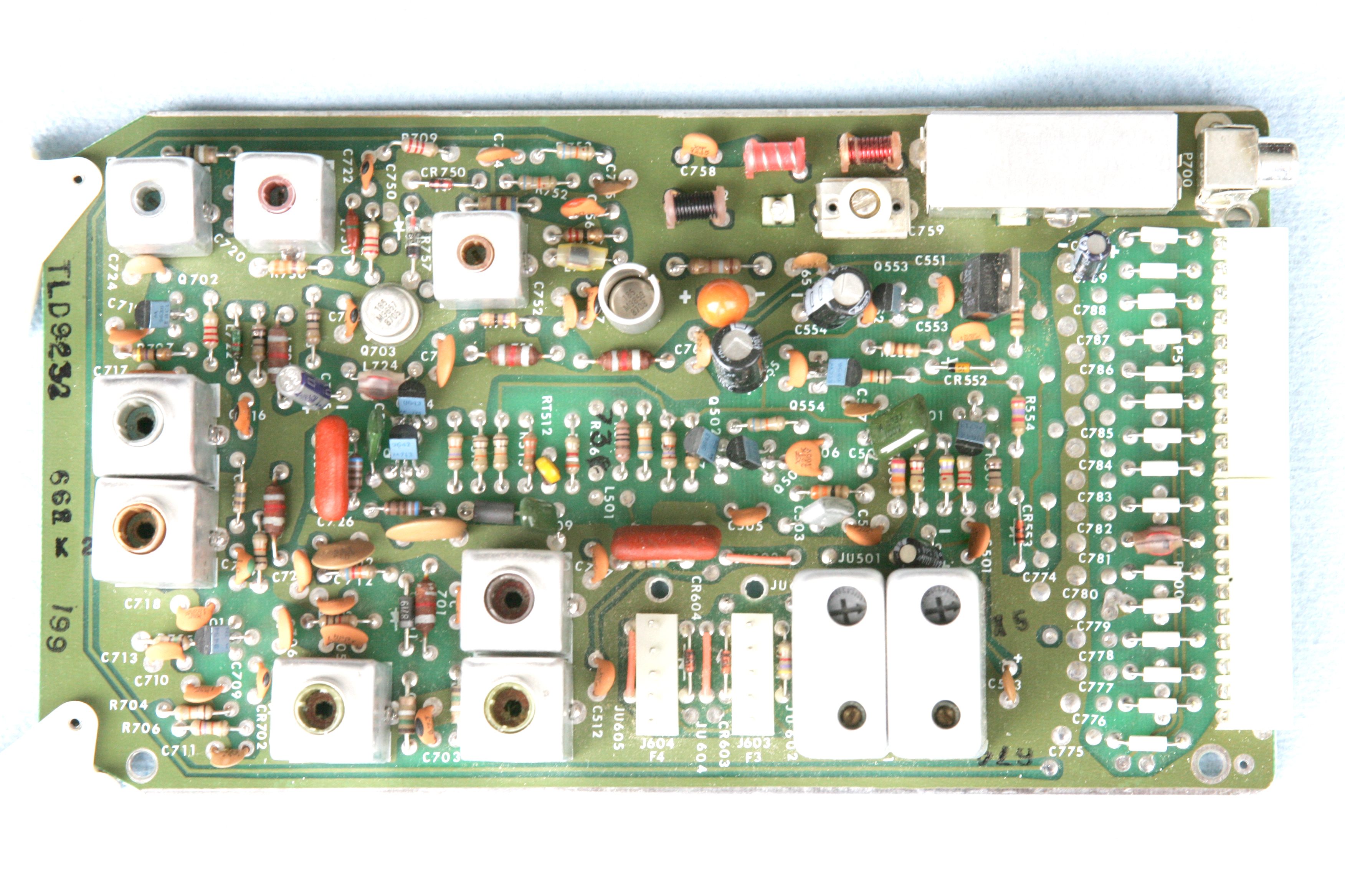
| TLD9232 | 146-174 | No | Simplex | Female |
TLD9232BPR top photo TLD9232BPR bottom photo both by Tim Ahrens W5FN |
||
| TLD9241 | 132-150.8 | Yes | Duplex | Male | |||
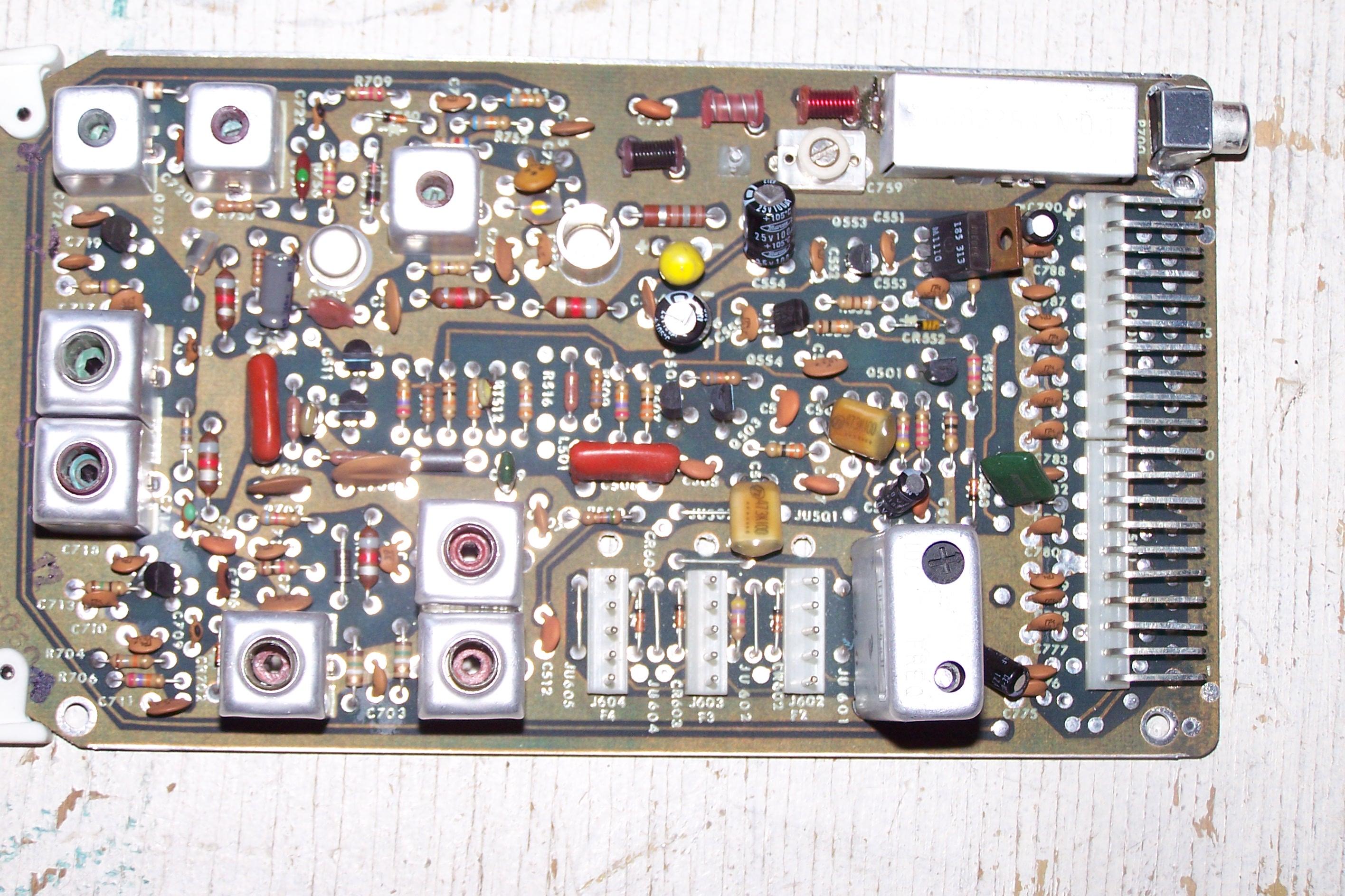
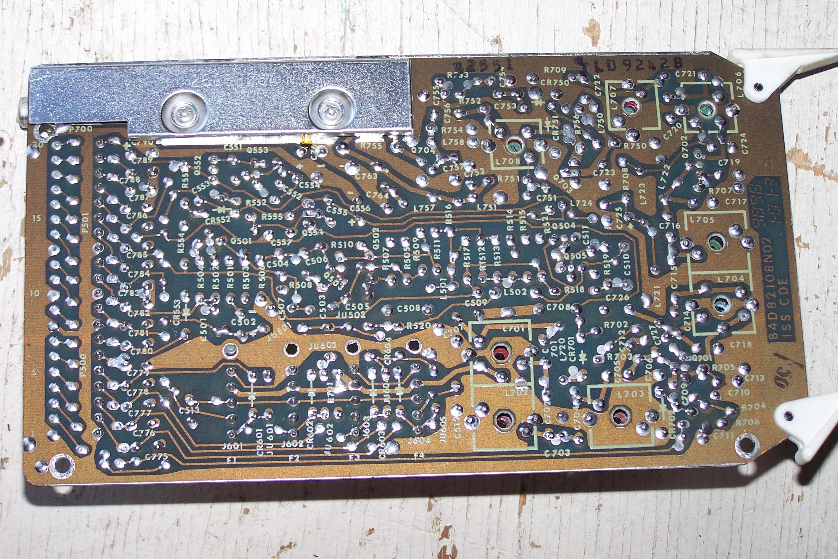
| TLD9242 | 146-174 | Yes | Duplex | Male | TLD9242B top photo TLD9242B bottom photo both by WA6ILQ |
||
|
All VHF exciters in 0.0005% service used the KXN1088 Channel Element. Those used in 0.0002% service used the KXN1095 Channel Element. The manuals that this information came are from my files, and are early versions. I know that there are additional exciters that were developed after my manuals were printed. If anyone has additional model numbers that should be in this list but are not just email me the information and I'll add them. If anyone can supply any of the missing photos we'd appreciate it. |
|||||||
| VHF High Band (132-174 MHz) Power Amplifiers | ||||||
|---|---|---|---|---|---|---|
| Model number (see note) |
Frequency MHz |
Power | Duty | Notes | ||
| TLD2532A | 150.8-162 | 60-110 | Intermittent | |||
| TLD2601 | 132-150.8 | 50-100 | Continuous | |||
| TLD2602 | 150.8-162 | 50-100 | Continuous | |||
| TLD2603 | 162-174 | 50-100 | Continuous | |||
|
The manuals that this information came are from my files, and are early versions. I know that there are additional intermittent duty amplifiers, plus several continuous duty power amplifiers that were developed after my manuals were printed, plus there are Canadian-specific amplifiers. If anyone has additional model numbers that should be in this list but are not just email me the information and I'll add them. If anyone can supply photos we'd appreciate it. |
||||||
| VHF High Band (132-174 MHz) Receivers | |||||||
|---|---|---|---|---|---|---|---|
| Model number (plus A or B suffix) (see note) |
Frequency MHz |
I.F. Frequency (see note) |
Filtering (see note) |
Mode | Module Connector |
Notes | |
| TRD6171 | 132-150.8 | 10.7 MHz | No | Simplex | Female | ||
| TRD6172 | 146-174 | 10.7 MHz | No | Simplex | Female | ||
| TRD6181 | 132-150.8 | 10.7 MHz | Yes | Duplex | Female | ||
| TRD6182 | 146-174 | 10.7 MHz | Yes | Duplex | Female |
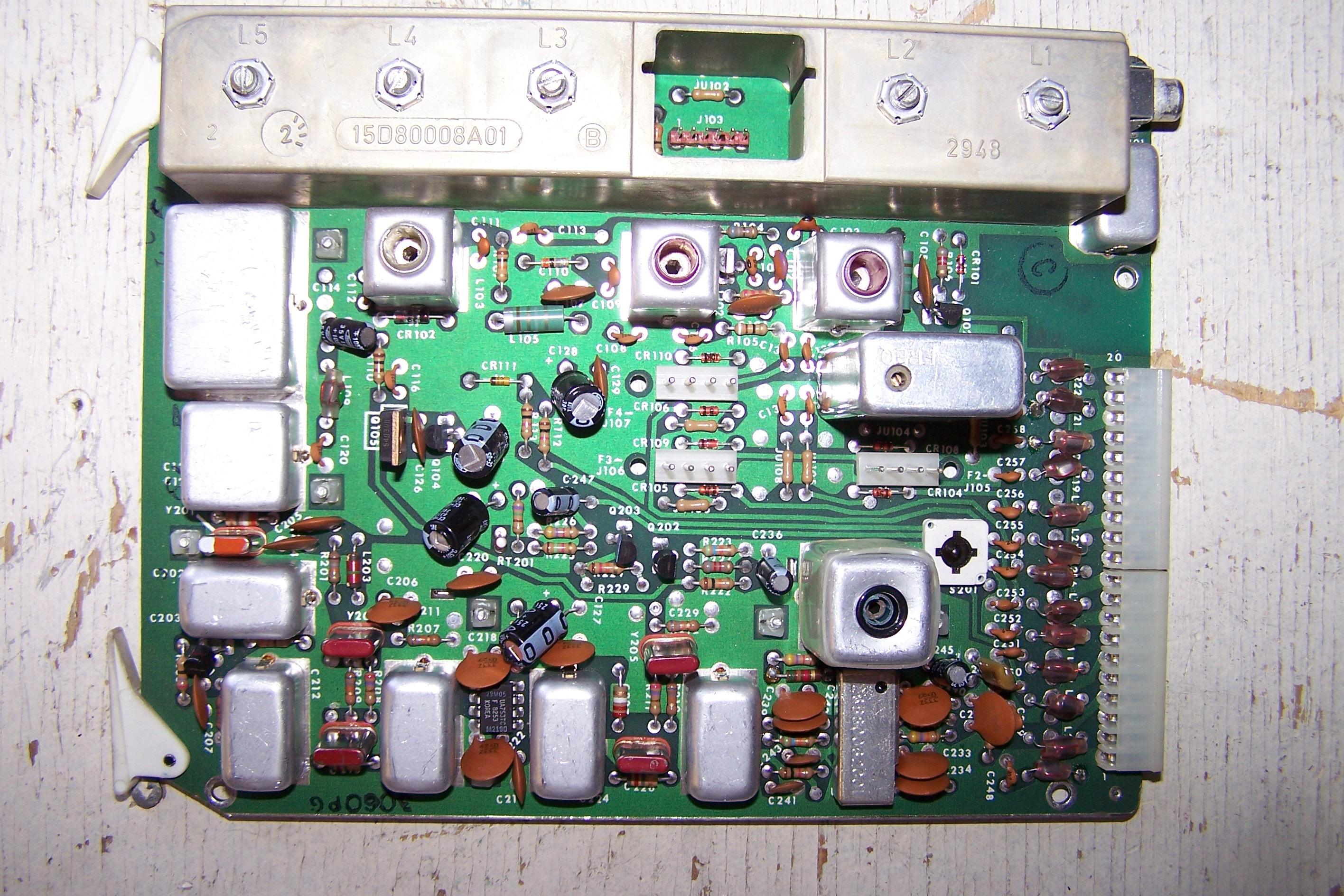
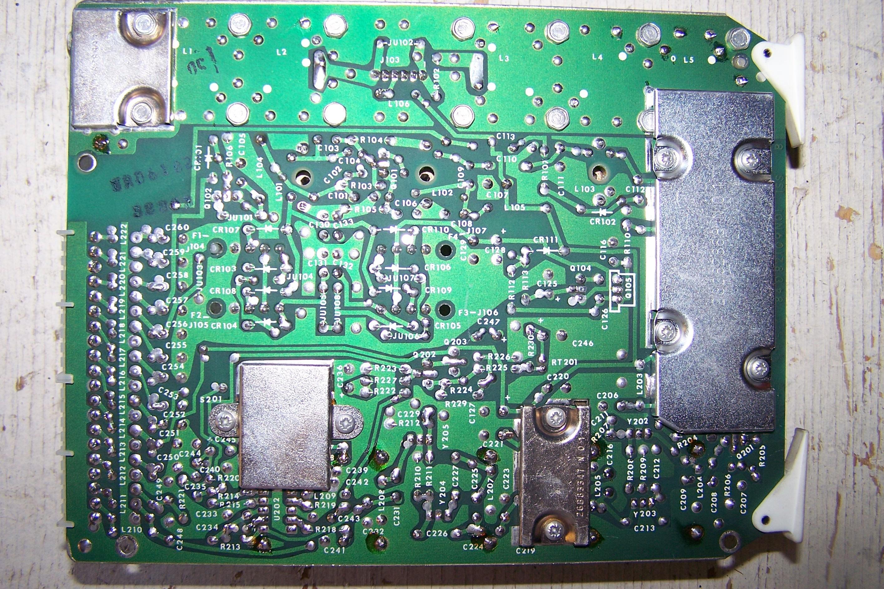
TRD6182A top photo TRD6182A bottom photo both by WA6ILQ |
|
| TRD6191 | 132-150.8 | 10.7 MHz | No | Duplex | Female | ||
| TRD6192 | 146-174 | 10.7 MHz | Yes | Duplex | Female | ||
| TRD6301 | 132-150.8 | 10.7 MHz | Yes | Duplex | Female | ||
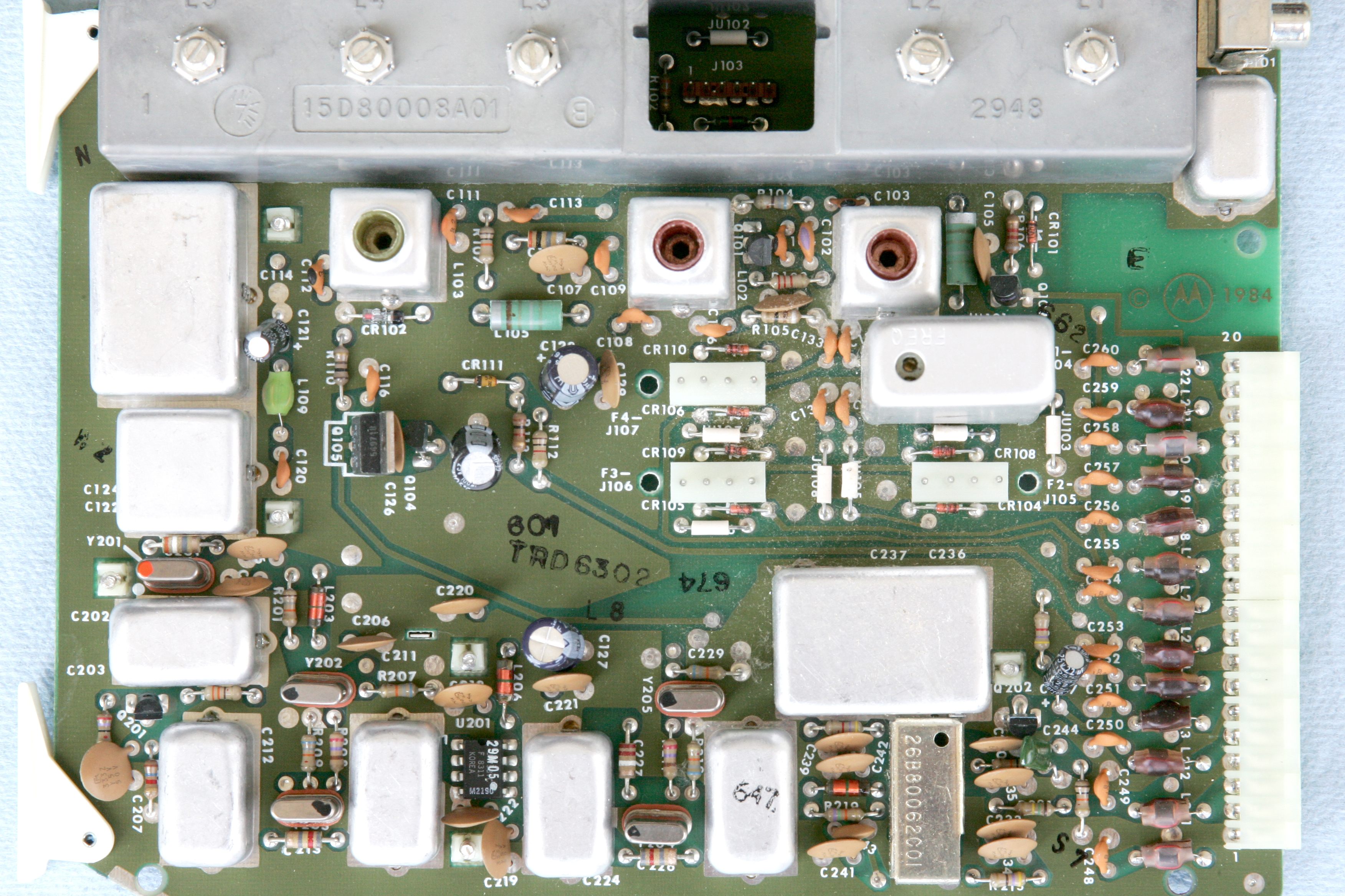
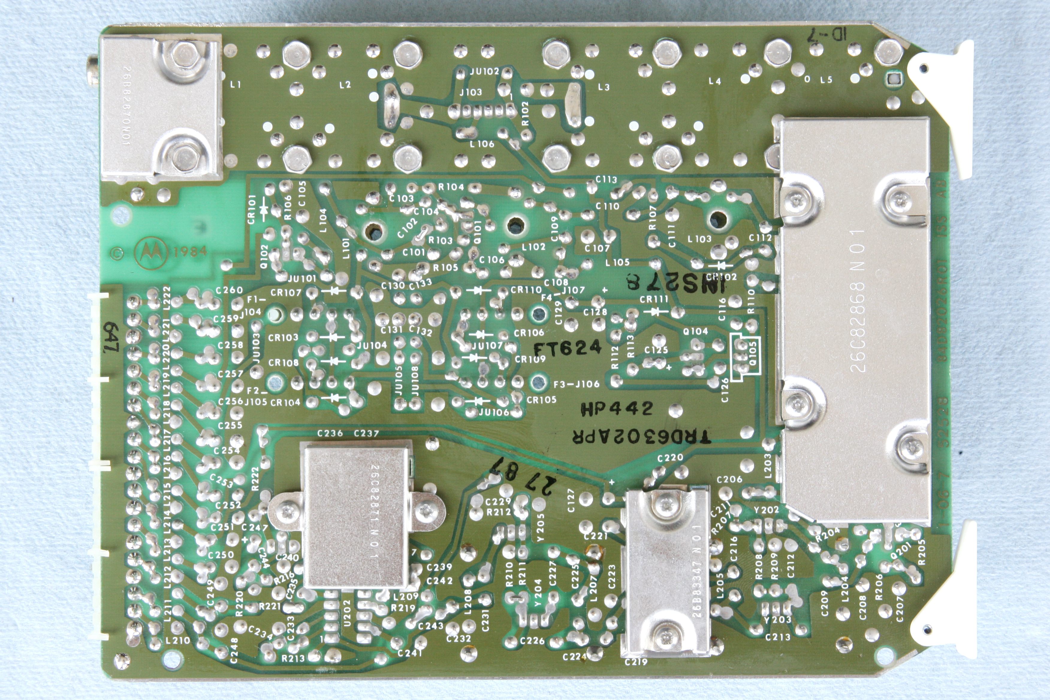
| TRD6302 | 146-174 | 10.7 MHz | Yes | Duplex | Female |
TRD6302APR top photo TRD6302APR bottom photo both by Tim Ahrens W5FN |
|
| TRD6311 | 132-150.8 | 10.8 MHz | Yes | Duplex | Female | ||
| TRD6312 | 146-174 | 10.8 MHz | Yes | Duplex | Female | ||
|
The TRD7171 / l72 are used with single receiver non-repeat (non-duplex) stations. The TRD6181 / l82 and the TRD6301 / l02 are normally used with either two-receiver stations or on repeater (duplex) stations. The TRD6191 / l92 and the TRD6311 / l12 are used with 2-receiver and repeater (duplex) stations where a shifted IF is required. All of these receivers can be configured for up to 4 frequencies, but no more than 2 MHz from lowest to highest frequency. |
|||||||
| All VHF receivers in 0.0005% service used the KXN1086
Channel Element. Those used in 0.0002% service used the KXN1112 Channel Element. The manuals that this information came are from my files, and are early versions. I know that there are additional receivers that were developed after my manuals were printed. If anyone has additional model numbers that should be in this list but are not just email me the information and I'll add them. If anyone can add the missing photos we'd appreciate it. |
|||||||
| UHF (406-512 MHz) Exciters | |||||||
|---|---|---|---|---|---|---|---|
| Model number (plus A or B suffix) (see note) |
Frequency MHz |
Filtering (see note) |
Mode | Module Connector |
Notes | ||
| TLE ? | 406-420 | ? | Simplex | ? | |||
| TLE ? | 406-420 | ? | Duplex | ? | |||
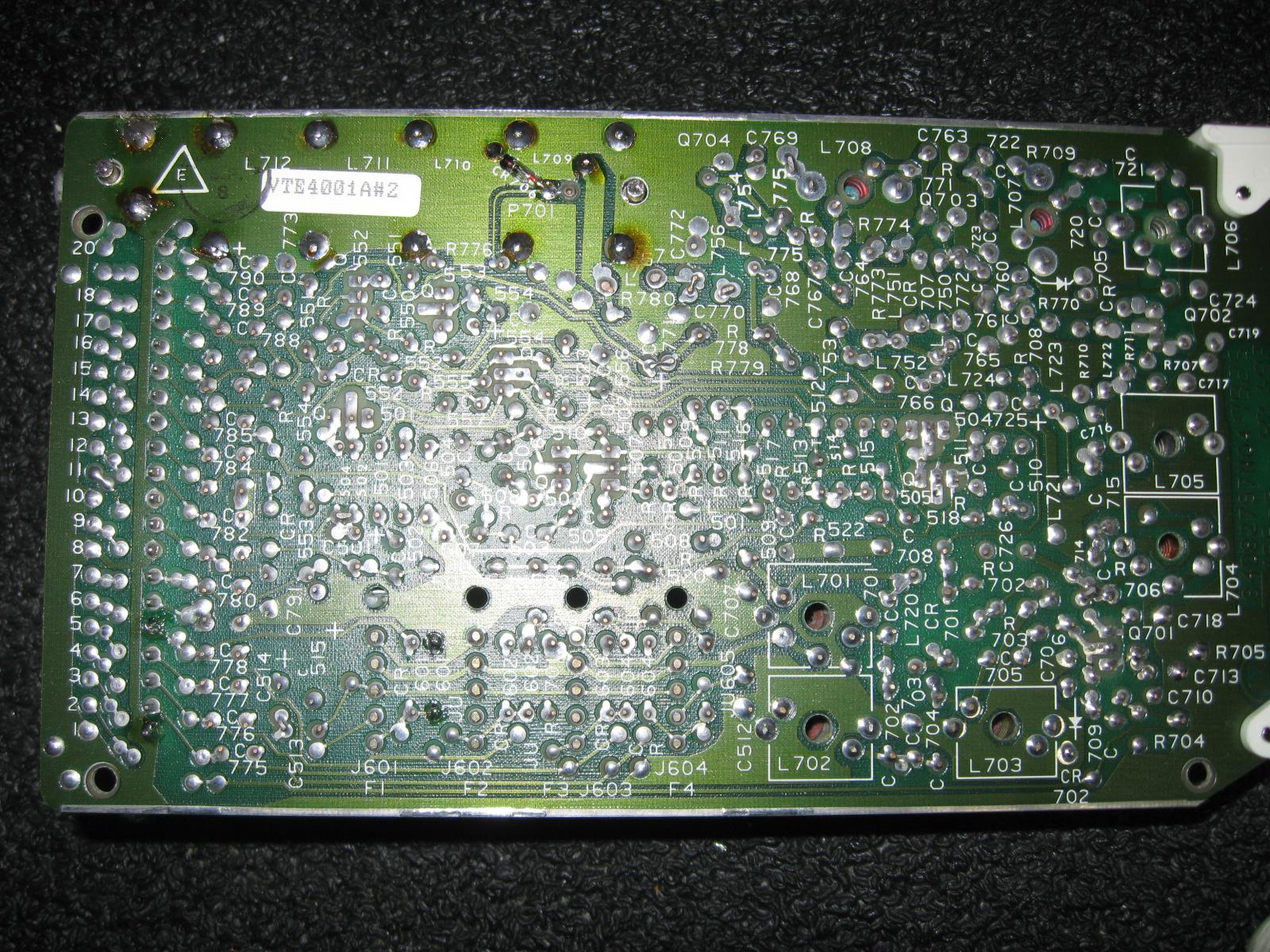
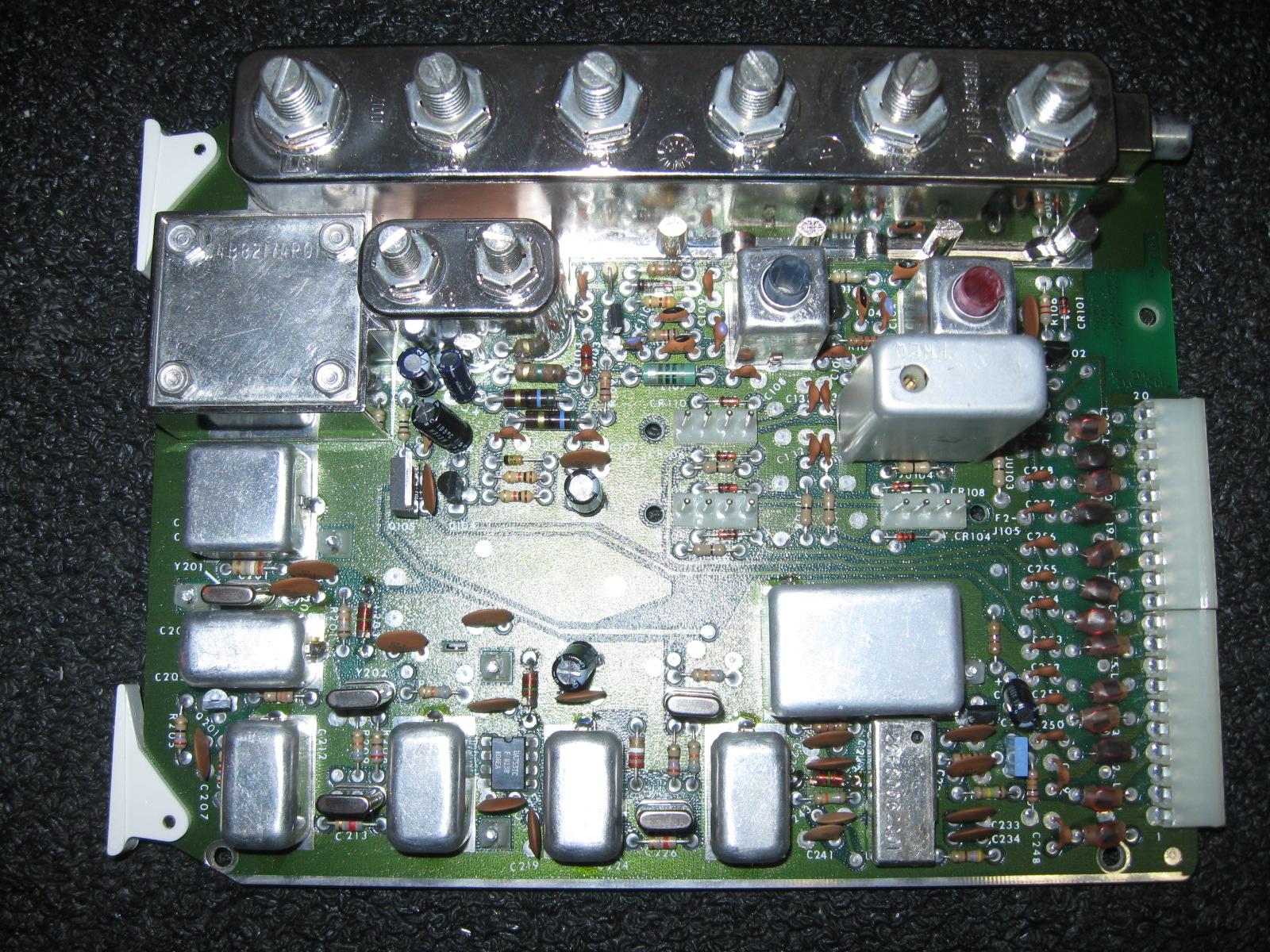
| VTE4001A | 406-420 | Yes | Duplex | Male |
VTE4001A top photo VTE4001A bottom photo both by VE2TSO |
||
| TLE5502 | 450-512 | No | Simplex | Female | |||
| TLE5512 | 450-512 | Yes | Duplex | Male | |||
|
All UHF exciters in 0.0005% service used the KXN1088 Channel Element, just like the VHF ones. Those used in 0.0002% service used the KXN1095 Channel Element. The VTE-series exciters were shipped only in the Canadian-built stations for use in Canada. The manuals that this information came are from my files, and are early version USA manuals. I know that there are additional exciters that were developed after my manuals were printed (for example, those on 406-420 MHz). If anyone has additional model numbers that should be in this list but are not just email me the information and I'll add them. If anyone can supply the missing photos we'd appreciate it. |
|||||||
| UHF (406-512 MHz) PA Decks | |||||||
|---|---|---|---|---|---|---|---|
| Model number (plus A or B suffix) (see note) |
Frequency MHz |
Power Watts |
Notes | ||||
| TLE2283 | 450-494 | 45-100 | |||||
| TLE2284 | 494-512 | 45-85 | Will not work on 440-450 MHz Amateur Radio or on 462 MHz GMRS | ||||
|
The manuals that this information came are from my files, and are early version
USA manuals. There are other USA models that I do not have here (for example, those on 406-420 MHz) plus there are the Canadian-only models. If anyone has additional model numbers that should be in this list but are not just email me the information and I'll add them. If anyone can supply photos we'd appreciate it. |
|||||||
| UHF (406-512 MHz) Receivers | ||||||
|---|---|---|---|---|---|---|
| Model number (plus A or B suffix) (see note) |
Frequency MHz |
I.F. Frequency (see note) |
Filtering (see note) |
Mode | Module Connector |
Notes |
| TRE ? | 406-420 | 10.7 MHz | ? | Simplex | ? | |
| TRE ? | 406-420 | 10.7 MHz | ? | Duplex | ? | |
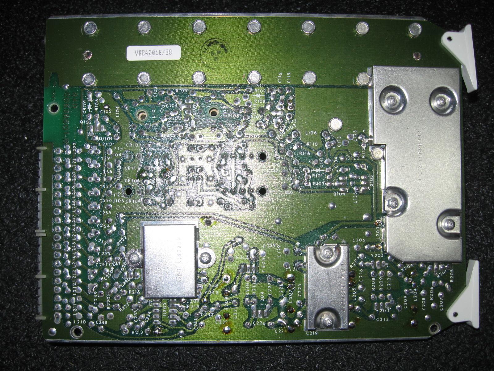
| VRE4001A | 406-420 | ? | Yes | Duplex | Female |
VRE4001A top photo VRE4001A bottom photo both by VE2TSO |
| TRE6152 | 450-470 | 10.7 MHz | No | Duplex | ? | |
| TRE6153 | 470-512 | 10.7 MHz | No | Simplex | ? | |
| TRE6162 | 450-470 | 10.7 MHz | Yes | Duplex | Female | |
| TRE6163 | 470-512 | 10.7 MHz | Yes | Duplex | Female | |
| TRE6172 | 450-470 | 10.8 MHz | Yes | Duplex | Female | |
| TRE6173 | 470-512 | 10.8 MHz | Yes | Duplex | Female | |
| TRE6262 | 450-470 | 10.7 MHz | Yes | Duplex | Female |
TRE6262A top photo by WA6ILQ |
| TRE6263 | 470-512 | 10.7 MHz | Yes | Duplex | Female | |
| TRE6272 | 450-470 | 10.8 MHz | Yes | Duplex | Female | |
| TRE6273 | 470-512 | 10.8 MHz | Yes | Duplex | Female | |
| The TRE6162 and 63 are the most common receivers. The TRE6172 is used where a shifted IF is required (i.e. 2-receiver stations). All of these receivers can be configured for up to 4 frequencies, but no more than 2 MHz from lowest to highest frequency. | ||||||
| A quick way to tell what split of UHF receiver you
have in your hand: If the UHF preselelector part number ends in "D56" you have a
450-470 MHz unit, if it ends in "D57" then you have a 470-512 unit. |
||||||
| All UHF receivers in 0.0005% service used the
KXN1086 Channel Element just like the VHF receivers. Those used in 0.0002% service used the KXN1112 Channel Element. The VRE-series receivers were shipped only in the Canadian-built stations for use in Canada. The manuals that this information came are from my files, and are early version USA manuals. I know that there are additional receivers that were developed after my manuals were printed (for example, those TRE-series on 406-420 MHz). If anyone has additional model numbers that should be in this list but are not just email me the information and I'll add them. If anyone can add the missing photos we'd appreciate it. |
||||||
So if you are looking for a used MSR repeater the ideal station is a xnnKSB-31xxBT, CT or DT series (where "x" is the appropriate letter and "n" is the appropriate number), and a GSB series will do just fine at reduced power and a with an added fan. And if you end up with a GSB series you really want to mount a second (backup) fan controlled by a thermostat.
By the way, after alignment of the receiver consider removing S201 (a rubber membrane type switch) on the receiver board if your receiver has one. It has been known to short and cause dead receiver symptoms. This is especially important if you are placing the repeater in a remote location. Personally, I replace it with a couple of pins that I can put a clip lead across when needed. I've been known to use couple of cut-off-resistor leads left over from stuffing a PC board, soldering and then trimming the leads.
And at some point open the harmonic filter on the PA and take a look around with a magnifying glass and take a good sniff as well... They have been known to burn internally, especially under out-of-tune conditions.
Useful MSR2000 Tools, Manuals, etc. Click here for instructions on how to order manuals.
Most of the books below are NLA (no longer available), if you want a paper copy try your local 2-way shop, the repeater-builder or "Motorola-User" yahoogroups, or eBay.
Like the predecessor, the MICOR, all MSR stations have two separate manuals and some of the options have their own separate manual. Most (if not all) MSR manuals are NLA (No Longer Available). If you try to order one you will be told that the manual has been canceled.
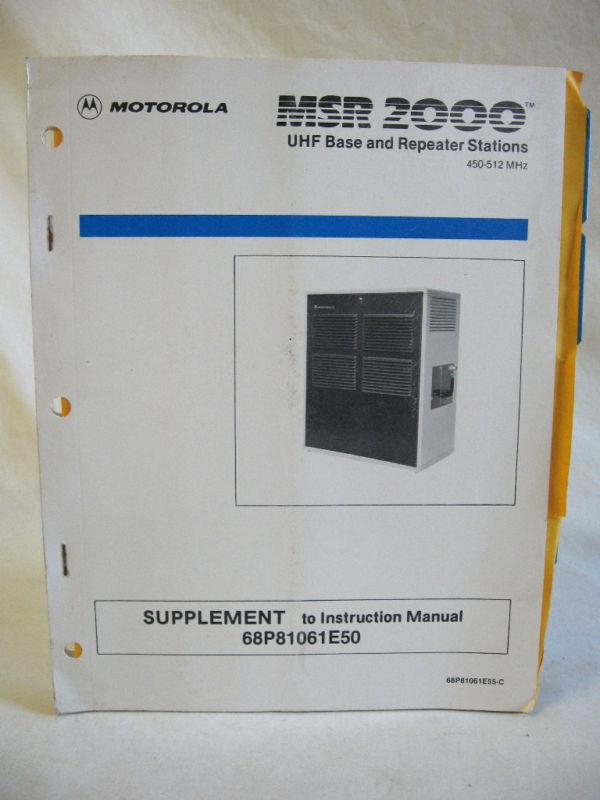
The first book that you will need to acquire is the "Control and Applications Manual", part number 6881061E40 (some literature called it the "Control and Audio" manual). This book covers everything that is not RF frequency dependent - mostly the control shelf. The second book you will need is the RF manual (this is frequency band dependent). At the time of this writing (mid 2009) all of the RF manuals were out of stock (but are PDF'd below).
To work on your base or repeater you will need BOTH the C&A Manual AND the appropriate frequency band RF manual... EXCEPT that the publications department at Moto made a major screw up... they put the power supply and accessory section into the VHF RF book. This means that if you have a UHF station you will need to print the power supply and accessory section from the high band PDFs below, or locate a VHF book just for the power supply and accessories.
Below we offer downloadable PDFs of the NLA manuals. Some are presented in both a smaller file and a larger file with better resolution. If you have the download time and the hard drive space you will want to get the bigger file.
Note that the Canadian MSRs had some significant differences - enough that there were Canadian manuals that had significant differences from USA manuals. One difference was that the Canadian manuals included the 40 watt PA decks that are not in the USA manuals. If anyone would like to do a descriptive article of the differences between the USA and Canadian models we'd be happy to add it to this page.
Another issue with the MSR manuals is that the UHF manual covers
450-512 MHz. There is another manual (or manual supplement) that
covers the 406-420 MHz stations. I do not know the part number,
I do not have one in my file cabinet, Moto does not list that manual
on it's web site, and none of the usual suspects has one in their
file cabinet.
Needless to say, if anyone has one, please let me know. If it's still
available I'd like to post the part number and price, if it's been
cancelled I'd like to get a scan of it and post it here.
Below is the same 61E40C manual but broken down into smaller sections. Note that the model tables are not in these smaller files. If you need them then you will need to get one of the two files above.
- Tab 1, Functional Description 2.1 MB PDF
- Tab 2, RF Control Chassis 5.8 MB PDF
Includes the TLN2472B ("Basic"), TLN2474B ("Fully optionable 2-receiver base") and TLN2475B ("Fully optionable repeater") RF chassis (this is the associated hardware and the backplane for the card cage).
The "Basic" backplane does not have the horizontal slots above the card cage. The "Fully optionable" backplanes do have them.
This section also covers the:
- TRN5081A Basic Backplane Interconnect Board
- TRN5083A Duplex Backplane Interconnect Board
- TRN5084A Two-Receiver Backplane Interconnect Board
- TRN5432A Basic Hardware kit
- TRN5433A 1-receiver and 4-Freq Hardware Kit
- TRN5435A Duplex Hardware Kit
- Tab 3, Remote Control 19.6 MB PDF
This section covers the:In most cases all you will need is the Station Control. Specific circumstances may require the Squelch Gate card. If you plan on stripping and reusing a cheap Timeout Timer card you might need that one.
- Station Control TRN5321A
- Line Driver TRN5235A, TRN5236A, TRN5237A, TRN5240A, TRN5254A, TRN5255A, TRN5256A
- DC Transfer TRN5239A,TRN5257A
- Guard Tone Decoder TLN2443A,TLN2450A
- F1 Tone Control TRN5320A, TRN5322A, TRN5327A, TRN5328A
- F2 Tone Control TLN2444A, TLN2449A, TLN5256A, TLN5325A
- Squelch Gate TRN5324A
- Time Out Timer TRN2442A
- Single Tone Decoder TLN2442A
- 4-Frequency Control Option Decoder TRN5296A
- Squelch, Repeater, and Private Line Control Option Decoder TRN1249A, TRN1250A, TRN1251A,
- Wild Card Control TLN2448A
- Tab 4, Audio-Squelch 14.8 MB PDF
This section covers the:You will need the R2 information only if you have (or plan on adding) a second receiver.
- R1 Audio and Squelch Module TRN5068A, TRN5069A, TRN9688A, TRN9689A
- R2 Audio and Squelch Module TRN5070A, TRN5071A, TRN5072A, TRN9690A, TRN9691A, TRN9692A
- Tone Private Line Encoder-Decoder Module TRN5073A, TRN5074A, TRN5075A (uses one or two KLN6209A reeds)
- Digital Private Line Encoder-Decoder Module TRN5076A, TRN5077A, TRN5078A (uses one or two TRN6005 code plugs)
- Tab 5, Optional Equipment 10.3 MB PDF
This section covers the:
- Spectra TAC Encoder Option (C269), consisting of:
- Spectra TAC 4-wire line Driver Module TRN5294A
- Spectra TAC Encoder Module TRN5293A
- Spectra TAC Squelch Gate Module TRN5331A
- MSR2000 Base and Repeater Multiple Tone PL Options (C158AB, C158AE, C261AC, C261AH, C262AE, C263AB), consisting of:
The multi-tone option requires modifying the basic PL module (the TRN5073, 74 or 75) in the station. The encoder is inserted in slot 12 of the card cage and allows encoding of one of 4 PL tones. The decoder is inserted in slot 11 and allows decoding of 4 different PL tones. The tones are determined by plug-in reeds. The encode tones need not match the decode tones. If the repeater controller has an internal controllable tone encoder (for example, the Scom 7330, or an Scom 7K with a TS-32 or a TS-64 are two that do) then the encoder card may not be needed.
- Multiple PL Maxtrix Control Module TRN5330A (this allows a tone remote to control the encoder and the decoder)
- Multiple PL Encoder Module TRN5292A
- Multiple PL Decoder Module TRN5329A (the table of contents in the PDF calls this an encoder module)
- MSR2000 UHF Accessories 2.35 MB PDF file
This section covers multiple items:
- TLE2403 Preamplifier,
- TLE551A receiver multi-coupler,
- T4084A, T4085A, T5002A, TLE2351A, TLE2363A and TLE6386A duplexers,
- TRN5864A antenna switch
- MSR2000 UHF Exciter 1.8 MB PDF file
TLE5502A Simplex, TLE5512A Duplex
This writeup has no information on the 406-420 MHz range boards.- MSR2000 UHF PA 2.1 MB PDF file
TLE2283A (45-100w, 450-494 MHz) and TLE2284A (45-85w, 494-512 MHz) power amplifiers.- MSR2000 UHF Receiver 1.8 MB PDF file
TRE6162A, TRE6163A, TRE6172A, TRE6173A
This writeup does not have any information on the 406-420 MHz range boards.- 6881114E65 = UHF Preamplifier TLE2403 - The manual is no longer available from Moto as a separate item, but it is inlcuded in the MSR2000 UHF Accessories PDF above. You only need this section if your station has this option, and frankly AngleLinear makes a much better preamp.
MSR2000 Configuration Notes, etc.
| Jumper (JU) orDiode (CR) |
In | Out | Suggested |
|---|---|---|---|
| JU1 | PL Filter Out | PL Filter In | Out |
| JU2 | For Spectra TAC Option | Normal | Out |
| JU101 | Normal | Remote Squelch Option | In |
| JU102 | For PL, DPL, Single Tone or Remote Squelch Operation | Normal | In |
| JU103 | Remote Squelch Operation | Normal | Out |
| JU104 | PL "OR" Squelch | PL AND Squelch | Out |
| JU105 | PL Squelch | Carrier Squelch | In |
| CR1 | Intercom Operation | Normal | In |
| CR2 | Normal | Intercom Operation | Out |
| CR106 | Normal | Repeater Operation | Out |
Alignment information and notes:
|
|
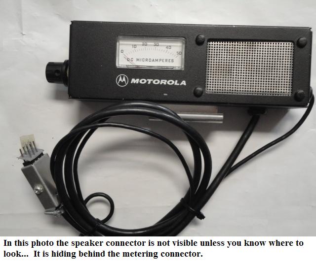
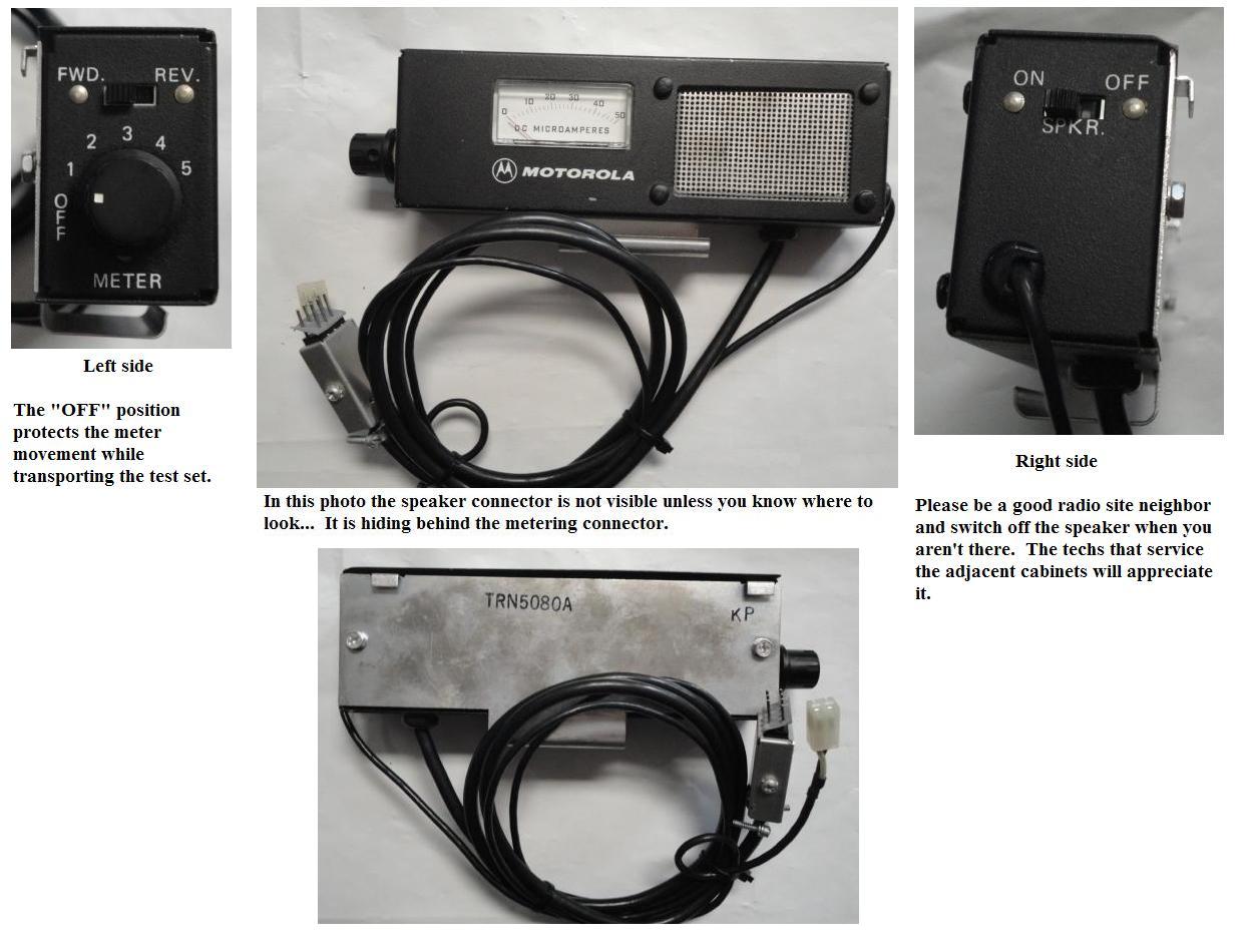
The official MSR2000 test set is the TRN5080 series (click
here for a photo)
or you could use a standard Moto Test Set with the proper cable kit (see
this page). Documentation, including schematic and parts list Photo courtesy of David Stanford K7IOU Anybody have a photo of the TRN5079 test speaker ? |
One of the handiest things to have around when you are realigning or troubleshooting a radio is a logbook that lists the meter readings from when it was working properly. I really suggest that you have a station logbook that starts the day you receive the station, with the first entry noting the date, the frequencies it was on when it was received, and a complete list of every meter reading of the receiver, exciter and PA deck on the old frequencies. Then after you realign the radio to your new frequencies repeat the process on the new frequencies. Just by looking at the numbers you can figure out what stage has taken a hit and won't tune.
The most overlooked step, and the real key to realigning the MSR2000 Receiver and Exciter modules is to follow the first pre-alignment step listed in the Service Manual: Back all the inductor (coil) cores out of their forms to the locations indicated in the chart / position table / pictures. You must do this when moving any module more than 1 MHz from the old frequency. Once that step is complete then you can start your new alignment from scratch. One of the meter dip / peak indications is very, very small and easy to pass over to the next wrong position so pay very special attention to the actual meter movement as you go through the steps.
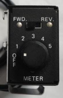
I'm going to put this in large type: You must use an analog meter for
the RF alignment. Moto made a test set specifically for the MSR2000 stations and
internally it is a 50µa meter. On the voltage scales it functions as a 20,000
ohms-per-volt voltmeter. There are two good reasons for this:
1) ALL of the metering points on radios of that era were configured to use either a
50µa meter to ground, or a 20k-ohms-per-volt meter, and the measurement circuit
uses the resistance of the test meter as part of a series circuit (from the test point
to ground). Without a load of the correct value none of the metering readings were meaningful.
2) There were no inexpensive portable digital multimeters (DMMs) when these radios were
being designed - every two-way tech had either a Motorola test set or a homebrew replacement,
or a portable VOM (a Simpson 260, a Triplett 630 or the WW2 surplus military equivalent)
that had a 50µa scale.The voltmeter scales were based on that 50µa movement
which produced a 20,000-ohms-per-volt voltmeter. Modern DMMs have a input impedance that
ranges from 2 to 11 megohms (depending on the manufacturer and model, most are
11 meg) and without the proper 20k-ohms-per-volt load none of the book measurement
values will be correct.
In other words, YOU CANNOT USE A MODERN DMM TO PROPERLY TUNE AN MSR2000.
Two additional "gotchas" are that most inexpensive DMMs go crazy in the presence of RF
energy due to the fact that they are sold by price, so to maximize the profit the
manufacturers scrimp on the shielding, and lastly, in every case you are tuning for a
peak or a dip - attempting to do that with dancing numbers on a DMM is an exercise in
frustration - you are constantly trying to determine if the new number is higher or
lower than the last number and your brain can't keep up with the DMM display update
rate. You are tuning for a peak or a dip, you NEED an analog needle meter to see the
peak or dip.
I received an email that disagrees:
I don't agree, in fact it's much easier for me to use my Fluke DMM to detect some of the very small meter peaks and dips. There is no rule or requirement the metering points have to be loaded by a 50µA movement.Interesting - My main portable DMM is a Fluke 73. But he makes a good point. Next time I'll use the DMM in parallel with the test set and try it.
Erratic metering with low cost Digital Multi Meters is probably the result of the price you paid.
"If it works, it must be a Fluke".
Another key to aligning / lrealigning the MSR2000 Receiver and Exciter strips is to
follow the first pre-alignment task item listed in the service manual: back all the
inductor (coil) cores out of their forms to the locations indicated in the slug position
graph. One useful trick is to put a flap of tape on the tuning tool - not only
does it help in counting turns but it also helps prevent the tool from rolling off the
workbench.
Then start your new alignment from scratch. At least one of the meter dip / peak
indications is very, very small and easy to miss. If you mistune that stage nothing after
it works right so pay very special attention to the actual meter needle movement as you
go through the manual steps and the various stages in the receiver and exciter.
![]() Alignment of the MSR2000 station VHF
receiver 180 KB PDF document
Alignment of the MSR2000 station VHF
receiver 180 KB PDF document
![]() Alignment of the MSR2000 station
VHF transmitter 4.6 MB PDF file
Alignment of the MSR2000 station
VHF transmitter 4.6 MB PDF file
This covers both intermittent and continuous duty models
![]() Alignment of the MSR2000 station UHF
receiver 176 KB PDF document
Alignment of the MSR2000 station UHF
receiver 176 KB PDF document
![]() Alignment of the MSR2000 station UHF
transmitter 1.2MB PDF document
Alignment of the MSR2000 station UHF
transmitter 1.2MB PDF document
Another transmitter alignment trick... have a DC ammeter in series with the
PA deck as you tune the station. You are looking for best efficiency, not
the absolute best power output.
Articles:
Contact Information:
The author can be contacted at: his-callsign // at // repeater-builder // dot // com.
Back to the top of the page
Up one level
Up two levels
Back to Home
This page was created August 1, 2009 by splitting the MSR2000 information off of the
Mitrek index page.
Thanks to Tim Ahrens W5FN for his photos.
Artistic layout and hand-coded HTML © Copyright 2005 and date of last update by
Mike Morris WA6ILQ.
Motorola® is a registered trademark of Motorola Inc. Image
used with permission.
Channel Element, Mitrek® and MSR2000® and a bunch more terms are registered
trademarks of Motorola Inc. So there!
This web page, this web site, the information presented in and on its pages and in these modifications and conversions is © Copyrighted 1995 and (date of last update) by Kevin Custer W3KKC and multiple originating authors. All Rights Reserved, including that of paper and web publication elsewhere.